|
|

Table Of Contents
FCC Safety Compliance Statement
Controller Discovery Process for Lightweight Access Points
Deploying the Access Points on the Wireless Network
Access Point Layout and Connectors
Suspended Ceiling Adjustable T-Rail Clips
Opening the Access Point Cover
Mounting the Access Point on a Horizontal or Vertical Surface
Mounting the Access Point Below a Suspended Ceiling
Mounting the Access Point Above a Suspended Ceiling
Mounting Access Point on a Network Cable Box
Mounting Access Point on a Desktop or Shelf
Attaching the Access Point to the Mounting Plate
Securing the Access Point to the Mounting Plate
Connecting the Ethernet and Power Cables
Connecting to an Ethernet Network with an Inline Power Source
Connecting to an Ethernet Network with Local Power
Installing the Access Point
This chapter describes the installation of the access point and includes these sections:
•
Warnings
•
•
•
•
•
•
•
•
•
•
•
•
Safety Information
Follow the guidelines in this section to ensure proper operation and safe use of the access point.
FCC Safety Compliance Statement
The FCC with its action in ET Docket 96-8 has adopted a safety standard for human exposure to radio frequency (RF) electromagnetic energy emitted by FCC certified equipment. When used with approved Cisco Aironet antennas, Cisco Aironet products meet the uncontrolled environmental limits found in OET-65 and ANSI C95.1, 1991. Proper installation of this radio according to the instructions found in this manual will result in user exposure that is substantially below the FCC recommended limits.
General Safety Guidelines
•
Warnings
Translated versions of the following safety warnings are provided in "Translated Safety Warnings."
Warning
SAVE THESE INSTRUCTIONS
Warning
Warning
Warning
20A Statement 1005
Warning
Statement 245B
Warning
Unpacking the Access Point
Follow these steps to unpack the access point:
Step 1
Step 2
Step 3
Package Contents
Each access point package contains the following items:
•
•
•
–
–
–
–
–
–
–
•
•
•
Basic Installation Guidelines
Because the access point is a radio device, it is susceptible to interference that can reduce throughput and range. Follow these basic guidelines to ensure the best possible performance:
•
•
http://www.cisco.com/en/US/products/hw/wireless/tsd_products_support_category_home.html
•
•
•
•
•
Controller Discovery Process for Lightweight Access Points
The lightweight access point supports these controller discovery processes:
•
•
•
You can also manually configure controller information using CLI commands on new (out-of-the-box) access points that are not connected to a controller. For additional information refer to the "Manually Configuring Controller Information Using the Access Point CLI" section on page 4-8.
Cisco recommends that you configure a DHCP server with Option 43 to provide the controller IP addresses to your lightweight access points. Cisco switches provide a DHCP server option that is typically used for this purpose.
Deploying the Access Points on the Wireless Network
Prior to beginning the actual access point deployment, perform these tasks:
•
•
•
–
–
–
To deploy your access points, follow these steps:
Step 1
Step 2
Step 3
a.
b.
c.
–
–
–
–
d.
e.
f.
Step 4
Access Point Layout and Connectors
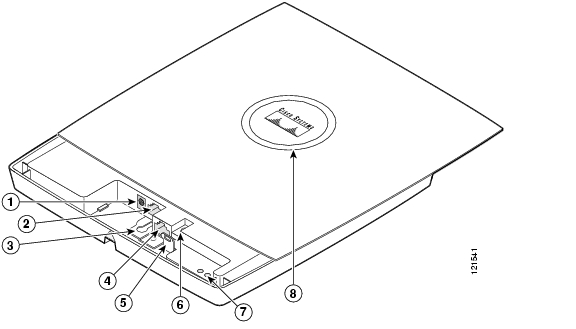
Figure 2-1 identifies the main access point hardware features.
Figure 2-1 Access Point Hardware Features
48-VDC power port
Ethernet port (RJ-45)
Mode button
Keyhole slot
Ethernet (E) and radio (R) LEDs
Console port (RJ-45)
Status LED
Note
Mounting Plate
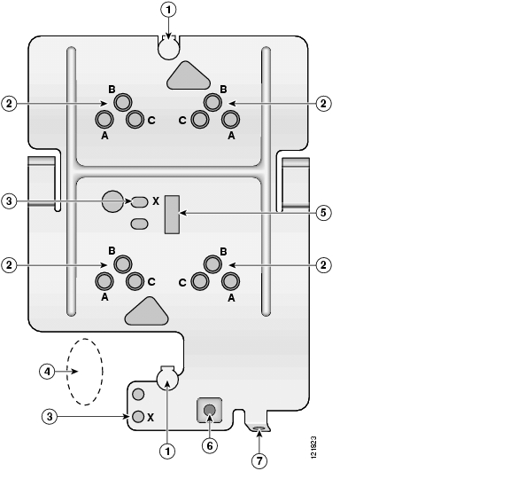
The access point mounting plate is designed to accomodate multiple mounting methods. The mounting holes on the plate are marked so that you can easily identify the correct holes for a specific mounting method. You can use the mounting plate as a template to mark the locations for the cable hole and the mounting holes for your wall or ceiling installation. Refer to Figure 2-2 to locate the various mounting holes for the method you intend to use.
Figure 2-2 Mounting Plate
Keyhole clips
T-bar hanger clip hole
Screw holes (A, B, C)
Security screw hole
Screw hole (X)
Padlock hole
Location for cable access hole
The mounting plate features are described below:
•
•
•
•
•
•
Note
Suspended Ceiling Adjustable T-Rail Clips
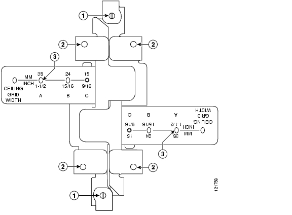
The accessory kit contains two suspended ceiling adjustable T-rail clips; one for standard ceiling tile rails and the other for recessed ceiling tile rails. The clips are adjustable to accomodate three standard T-rail widths. Each clip contains detents that are used to adjust the clip to the T-rail. Each detent contains markings that indicate the T-rail width and the hole letter that corresponds to the correct mounting holes on the mounting plate. Figure 2-3 shows the details of the adjustable T-rail clips.
Figure 2-3 T-Rail Clip Features
T-rail locking screws
T-rail width adjustment detents (A, B, C) correspond to the A, B, and C holes on the mounting plate
Mounting plate screw holes
(8 x 32 flat head screw)
The adjustable T-rail clip attaches to the mounting plate using four 6 x 32 x 1/4 inch flat head screws. The A, B, and C holes on the T-rail clips and the mounting plate correspond to these T-rail widths:
•
•
•
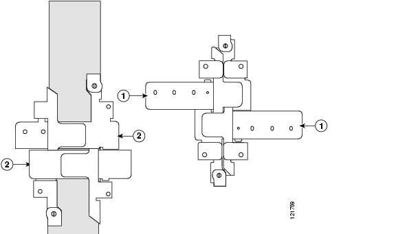
Figure 2-4 indicates where you should push to open and close the adjustable T-rail clips.
Figure 2-4 Adjusting the T-Rail Clips
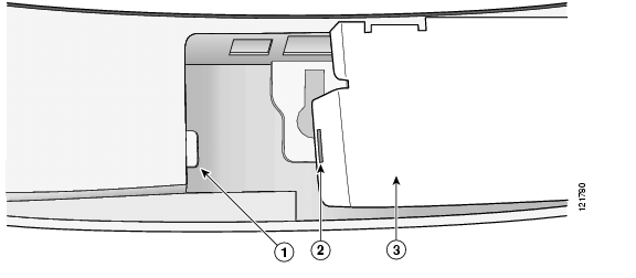
Opening the Access Point Cover
The top cover provides access to the cable bay area containing the power connector, Ethernet port, console serial port, the mode button, and the Ethernet and Radio LEDs.
Caution
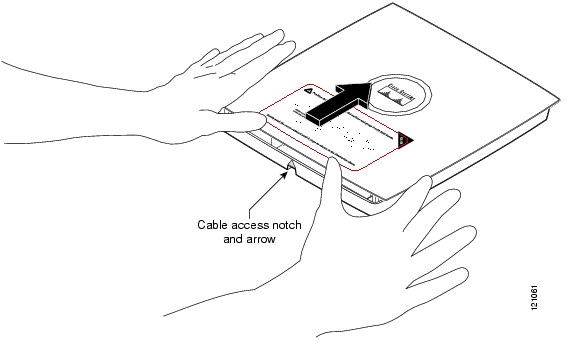
The cover is designed to partially open by sliding back from a secured position. Follow these steps to open the top cover:
Step 1
Figure 2-5 Opening the Access Point Cover
Step 2
Step 3
Mounting the Access Point on a Horizontal or Vertical Surface
Follow these steps to mount the access point on a horizontal or vertical surface:
Step 1
Note
Figure 2-6 Mounting Plate
Keyhole clip
T-bar hanger clip hole
Screw holes (A, B, C)
Security screw hole
Screw hole (X)
Padlock hole
Location for cable access hole
Step 2
Step 3
Step 4
Note
Step 5
Step 6
To attach the access point to the mounting plate, see "Attaching the Access Point to the Mounting Plate" section.
Mounting the Access Point Below a Suspended Ceiling
You should review Figure 2-7 before beginning the mounting process.
Figure 2-7 Adjustable T-Rail Clips
Follow these steps to mount your access point on a suspended ceiling:
Step 1
Step 2
Step 3
Step 4
Step 5
Step 6
Step 7
Step 8
To attach the access point to the mounting plate, see "Attaching the Access Point to the Mounting Plate" section.
Mounting the Access Point Above a Suspended Ceiling
The access point mounting bracket is designed to be integrated into the T-bar grid above the tiles of a suspended ceiling. The access point uses a T-bar box hanger (not supplied) such as the Erico Caddy 512 or B-Line BA12 and should be oriented just above the top surface of a standard 5/8-in. (1.59-cm) ceiling tile. You may need to modify a thicker tile to allow room for the access point.
Caution
Caution
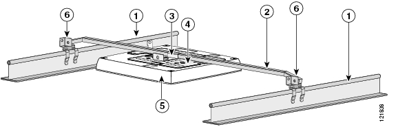
Follow these steps to mount the access point above a suspended ceiling. Refer to Figure 2-8 before proceeding.
Figure 2-8 T-Bar Grid Mounting Bracket Parts
Suspended ceiling T-rail
Access point mounting bracket
T-bar box hanger
Access point
Bracket mounting clip
T-rail clip
Step 1
Step 2
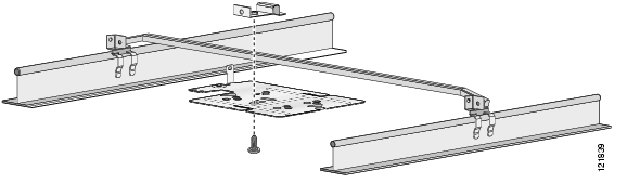
Figure 2-9 T-Bar and Mounting Bracket
Step 3
Step 4
Step 5
Step 6
Step 7
Step 8
Step 9
Step 10
Mounting Access Point on a Network Cable Box
Follow these steps to mount the access point on a network cable box.
Step 1
Step 2
Step 3
To attach the access point to the mounting plate, see the "Attaching the Access Point to the Mounting Plate" section.
Mounting Access Point on a Desktop or Shelf
When placing the access point on a desktop of shelf, you do not need the mounting plate. The access point has four rubber pads on the bottom to help prevent sliding or scratching the surface of your desktop or shelf. For information on connecting the access point cables, see the "Connecting the Ethernet and Power Cables" section.
Attaching the Access Point to the Mounting Plate
Follow these steps to attach the access point to the mounting plate:
Step 1
Step 2
Step 3
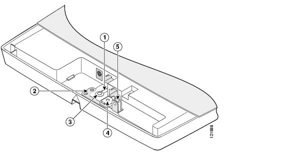
Figure 2-10 Aligning the Keyhole Clip to the Access Point Keyhole
Access point keyhole
Security screw hole
Mounting plate
Padlock hole
Mounting plate keyhole clip
Step 4
Step 5
Step 6
For instructions on connecting your cables, refer to the "Connecting the Ethernet and Power Cables" section.
For instructions on securing your access point, refer to the "Securing the Access Point" section.
Securing the Access Point
There are two ways to secure your access point:
•
•
Using a Security Cable
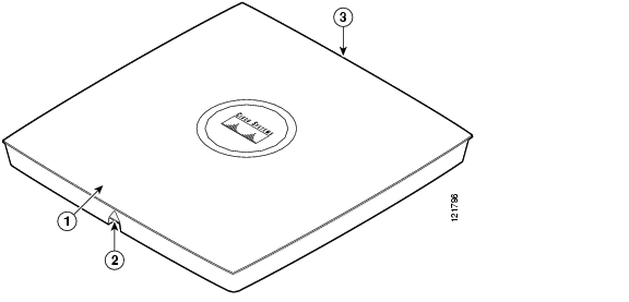
You can secure the access point by installing a standard security cable (such as the Kensington Notebook MicroSaver, model number 64068) into the access point security cable slot (see Figure 2-5). The security cable can be used with any of the mounting methods described in this guide.
Figure 2-11 Security Cable Slot
Follow these steps to install the security cable.
Step 1
Step 2
Step 3
Step 4
Step 5
Securing the Access Point to the Mounting Plate
The mounting plate provides two methods of securing your access point to restrict its removal:
•
Note
•
Note
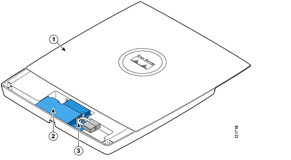
Follow these instructions to install the security hasp adapter:
Step 1
Step 2
Figure 2-12 Installing the Security Hasp Adapter
Step 3
Step 4
Step 5
Figure 2-13 Padlock
Step 6
Step 7
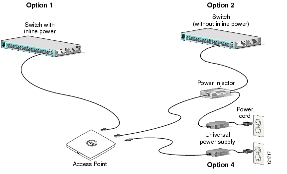
Connecting the Ethernet and Power Cables
The access point receives power through the Ethernet cable or an external power module. Figure 2-14 shows the power options for the access point.
Figure 2-14 Access Point Power Options
Warning
The access point supports the following power sources:
•
•
–
–
–
Note
Connecting to an Ethernet Network with an Inline Power Source
Caution
Note
Follow these steps to connect the access point to the Ethernet LAN when you have an inline power source:
Step 1
Step 2
Step 3
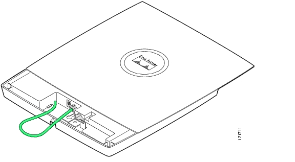
Figure 2-15 Looping the Ethernet Cable
Step 4
Step 5
Step 6
Step 7
•
•
Connecting to an Ethernet Network with Local Power
Caution
Note
Follow these steps to connect the access point to an Ethernet LAN when you are using a local power source:
Step 1
Step 2
Step 3
Step 4
Step 5
Step 6
Step 7
Step 8
Step 9
Step 10
For information on securing your access point, see the "Securing the Access Point" section.
Rotating the Cisco Logo
The Cisco logo on the top of the unit can be rotated to correctly position the logo for any mounting arrangement; for example, when the unit is mounted on a vertical wall. The logo should always be easy to read.
To rotate the Cisco logo, follow these steps:
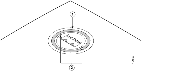
Step 1
Figure 2-16 Cisco Logo Holes
Step 2
Step 3
![]()
![]()
![]()
![]()
![]()
![]()
![]()
![]()
Posted: Thu Apr 26 01:53:25 PDT 2007
All contents are Copyright © 1992--2007 Cisco Systems, Inc. All rights reserved.
Important Notices and Privacy Statement.