|
|

Table Of Contents
Network Configuration Examples
Repeater Unit that Extends Wireless Range
Central Unit in an All-Wireless Network
Overview
Cisco Aironet 1130AG Series Access Points combine mobility and flexibility with the enterprise-class features required by networking professionals. With a management system based on Cisco IOS software, the 1130AG series access point is a Wi-Fi certified, wireless LAN transceiver.
The access point contains two integrated radios: a 2.4-GHz radio (IEEE 802.11g) and a 5-GHz radio (IEEE 802.11a). You can configure the radios separately, using different settings on each.
The access point connects wireless and wired networks or is the center point of a stand-alone wireless network. In large installations, wireless users within radio range of an access point can roam throughout a facility while maintaining seamless, uninterrupted access to the network.
You can configure and monitor the access point using the command-line interface (CLI), the browser-based management system, Simple Network Management Protocol (SNMP), or Cisco Structured Wireless-Aware Network (SWAN).
This chapter provides information on the following topics:
•
Network Configuration Examples
Hardware Features
Key hardware features of the access point include:
•
•
•
•
•
•
•
Refer to "Access Point Specifications," for a list of access point specifications.
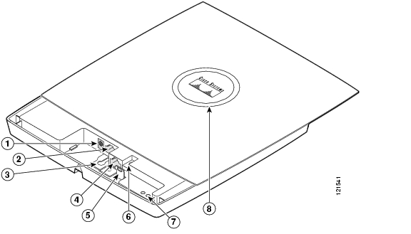
Figure 1-1 shows the access point hardware features.
Figure 1-1 Access Point Hardware Features
48-VDC power port
Ethernet port (RJ-45)
Mode button
Keyhole slot
Ethernet (E) and radio (R) LEDs
Console port (RJ-45)
Status LED
Dual-Radio Operation
The access point supports simultaneous radio operation using a 2.4-GHz 802.11g radio and a 5-GHz 802.11a radio. Each radio uses dual-diversity integrated antennas.
The 5-GHz radio incorporates an Unlicensed National Information Infrastructure (UNII) radio transceiver operating in the UNII 5-GHz frequency bands. The 802.11g radio is called Radio0 and the 802.11a radio is called Radio1.
Ethernet Port
The auto-sensing Ethernet port accepts an RJ-45 connector, linking the access point to your 10BASE-T or 100BASE-T Ethernet LAN. The access point can receive power through the Ethernet cable from a power injector, switch, or power patch panel. The Ethernet MAC address is printed on the label on the back of the access point (refer to Figure 1). The port is located in a cable bay area that is hidden by the closed top cover (see Figure 1-1).
Note
Console Port
The serial console port provides access to the access point's command-line interface (CLI) using a terminal emulator program. The port is located in a cable bay area that is hidden by the top cover (see Figure 1-1). Use an RJ-45 to DB-9 serial cable to connect your computer's COM port to the access point's serial console port. (Refer to "Console Cable Pinouts," for a description of the console port pinouts.) Assign the following port settings to a terminal emulator to open the management system pages: 9600 baud, 8 data bits, No parity, 1 stop bit, and no flow control.
Note
LEDs
The access point has three LEDs to indicate Ethernet activity, radio activity, and status indications (refer to the "Checking the Access Point LEDs" section on page 6-2 for additional information).
•
•
•
Note
Figure 1-1 shows the locations of the three LEDs.
Power Sources
The access point can receive power from an external power module or from inline power using the Ethernet cable. The access point supports the IEEE 802.3af inline power standard and Cisco CDP Power Negotiation. Using inline power, you do not need to run a power cord to the access point because power is supplied over the Ethernet cable.
Warning
Caution
The access point supports the following power sources:
•
•
–
–
–
Note
UL 2043 Certification
The access point has adequate fire resistance and low smoke-producing characteristics suitable for operation in a building's environmental air space, such as above suspended ceilings, in accordance with Section 300-22(c) of the NEC, and with Sections 2-128, 12-010(3) and 12-100 of the Canadian Electrical Code, Part 1, C22.1.
Caution
Anti-Theft Features
There are three methods of securing the access point:
•
•
Note
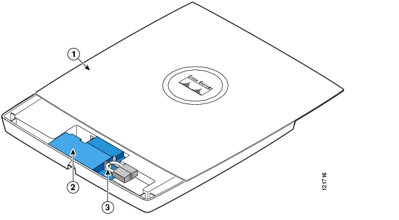
Figure 1-2 Access Point with Security Hasp Adapter
\
•
–
Note
–
Note
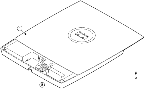
Figure 1-3 Access Point Security Screw Hole
Network Configuration Examples
This section describes the access point's role in three common wireless network configurations. The access point's default configuration is as a root unit connected to a wired LAN or as the central unit in an all-wireless network. The repeater role requires a specific configuration.
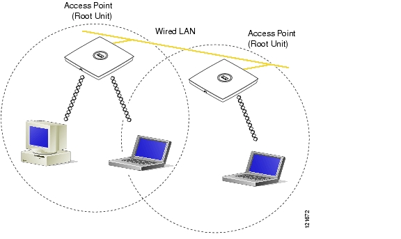
Root Unit on a Wired LAN
An access point connected directly to a wired LAN provides a connection point for wireless users. If more than one access point is connected to the LAN, users can roam from one area of a facility to another without losing their connection to the network. Figure 1-4 shows access points acting as root units on a wired LAN.
Figure 1-4 Access Points as Root Units on a Wired LAN
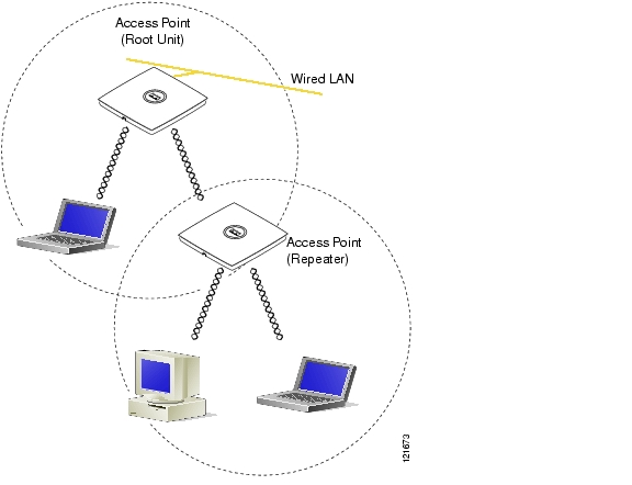
Repeater Unit that Extends Wireless Range
An access point can be configured as a stand-alone repeater to extend the range of your infrastructure or to overcome an obstacle that blocks radio communication. The repeater forwards traffic between wireless users and the wired LAN by sending packets to either another repeater or to an access point connected to the wired LAN. The data is sent through the route that provides the best performance for the client. Figure 1-5 shows an access point acting as a repeater. Consult the Cisco IOS Software Configuration Guide for Cisco Aironet Access Points for instructions on setting up an access point as a repeater.
Note
Figure 1-5 Access Point as Repeater
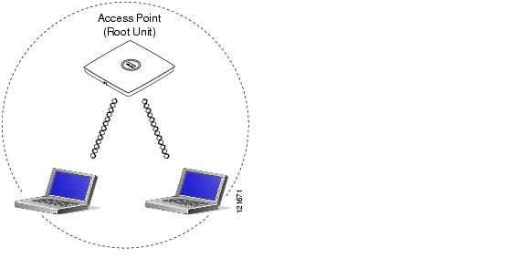
Central Unit in an All-Wireless Network
In an all-wireless network, an access point acts as a stand-alone root unit. The access point is not attached to a wired LAN; it functions as a hub linking all stations together. The access point serves as the focal point for communications, increasing the communication range of wireless users. Figure 1-6 shows an access point in an all-wireless network.
Figure 1-6 Access Point as Central Unit in All-Wireless Network
![]()
![]()
![]()
![]()
![]()
![]()
![]()
![]()
Posted: Fri Apr 29 17:18:54 PDT 2005
All contents are Copyright © 1992--2005 Cisco Systems, Inc. All rights reserved.
Important Notices and Privacy Statement.