cc/td/doc/product/wireless/airo1130
hometocprevnextglossaryfeedbacksearchhelp
PDF

Table Of Contents

Troubleshooting

Checking the Access Point LEDs

Checking Basic Settings

Default IP Address Behavior

Default SSID and Radio Behavior

Enable Radio Interfaces

SSID

WEP Keys

Security Settings

Low Power Condition

Intelligent Power Management

Configuring Power Using the CLI

Configuring the Access Point System Power Settings Using a Browser

Running the Carrier Busy Test

Running the Ping Test

Resetting to the Default Configuration

Using the MODE Button

Using the Web Browser Interface

Reloading the Access Point Image

Using the MODE Button

Web Browser Interface

Obtaining the Access Point Image File

Obtaining the TFTP Server Software


Troubleshooting


This chapter provides troubleshooting procedures for basic problems with the access point. For the most up-to-date, detailed troubleshooting information, refer torefer to the Cisco Technical Support and Documentation website at the following URL:

http://www.cisco.com/en/US/products/hw/wireless/tsd_products_support_category_home.html

Sections in this chapter include:

Checking the Access Point LEDs

Checking Basic Settings

Low Power Condition

Running the Carrier Busy Test

Running the Ping Test

Resetting to the Default Configuration

Reloading the Access Point Image

Obtaining the Access Point Image File

Obtaining the TFTP Server Software

Checking the Access Point LEDs

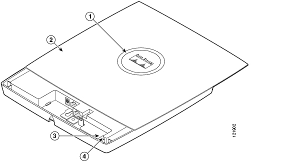
If your access point is not working properly, check the Status LED on the top panel or the Ethernet and Radio LEDs in the cable bay area. You can use the LED indications to quickly assess the unit's status. Figure 6-1 shows the access point LEDs (for additional information refer to the Event Log using the access point browser interface).

Figure 6-1 Access Point LEDs

1

Status LED

3

Ethernet LED

2

Access point cover

4

Radio LED


Note To view the Ethernet and Radio LEDs you must open the access point cover (refer to the "Opening the Access Point Cover" section on page 2-9).


Note When the access point cover is opened, the Status LED colors are not visible.


Note There can be slight color variations in the Status LED of each access point.


The LED signals are listed in Table 6-1.

Table 6-1 LED Signals

Message type
Cable Bay Area
Top of Unit
Meaning
Ethernet LED
Radio LED

Status LED

Boot loader status

Green

Green

Green

DRAM memory test ok.

Off

Blinking green

Blue-green

Initialize Flash file system.

Off

Green

Pink

Flash memory test ok.

Green

Off

Dark blue

Ethernet test ok.

Green

Green

Green

Starting Cisco IOS.

Association status

Light green

Normal operating condition, but no wireless client devices are associated with the unit.

Blue

Normal operating condition, at least one wireless client device is associated with the unit.

Operating status

Green

Ethernet link is operational.

Blinking green

Transmitting or receiving Ethernet packets.

Blinking green

Transmitting or receiving radio packets.

Blinking
dark blue

Software upgrade in progress

Boot loader warnings

Off

Off

Yellow

Ethernet link not operational.

Red

Off

Yellow

Ethernet failure.

Amber

Off

Yellow

Configuration recovery in progress
(Mode button pressed for 2 to 3 seconds).

Off

Red

Pink

Image recovery
(Mode button pressed for 20 to 30 seconds)

Blinking green

Red

Blinking pink and off

Image recovery in progress and Mode button is released.

Boot loader errors

Red

Red

Red

DRAM memory test failure.

Off

Red

Blinking red and blue

Flash file system failure.

Off

Amber

Blinking red and blue-green

Environment variable (ENVAR) failure.

Amber

Off

Blinking red and yellow

Bad MAC address.

Red

Off

Blinking red and off

Ethernet failure during image recovery.

Amber

Amber

Blinking red and off

Boot environment error.

Red

Amber

Blinking red and off

No Cisco IOS image file.

Amber

Amber

Blinking red and off

Boot failure.

Cisco IOS errors

Blinking amber

Transmit or receive Ethernet errors.

Blinking amber

Maximum retries or buffer full occurred on the radio.

Red

Red

Amber

Software failure; try disconnecting and reconnecting unit power.

Amber

General warning, insufficient inline power (see the Low Power Condition section).


Checking Basic Settings

Mismatched basic settings are the most common causes of lost connectivity with wireless clients. If the access point does not communicate with client devices, check the following areas.

Default IP Address Behavior

When you connect an 1130AG access point running Cisco IOS Release 12.3(2)JA or later software with a default configuration to your LAN, the access point requests an IP address from your DHCP server, and if it does not receive an IP address, it continues to send requests indefinitely.

Default SSID and Radio Behavior

In Cisco IOS Relese 12.3(2)JA2 and earlier, the access point radios are enabled by default and the default SSIDs are tsunami.

In Cisco IOS Release 12.3(4)JA, the access point radios are disabled by default, and there are no default SSIDs. You must create an SSID and enable the radio before the access point will allow wireless associations from other devices. These changes to the default configuration improve the security of newly installed access points. Refer to the "Configuring Basic Security Settings" section for instructions on configuring the SSID and the "Enable Radio Interfaces" section for instructions on enabling the radio interfaces.

Enable Radio Interfaces

To enable the radio interfaces, follow these instructions:


Step 1 Use your web-browser to access your access point.

Step 2 When the Summary Status page displays, click Network Interfaces > Radio0-802.11B or Radio0-802.11G and the radio status page displays.

Step 3 Click Settings and the radio settings page displays.

Step 4 Click Enable in the Enable Radio field.

Step 5 Click Apply.

Step 6 Click Network Interfaces > Radio0-802.11A and the radio status page displays.

Step 7 Click Settings and the radio settings page displays.

Step 8 Click Enable in the Enable Radio field.

Step 9 Click Apply.

Step 10 Close your web-browser.


SSID

Wireless clients attempting to associate with the access point must use the same SSID as the access point. If a client device's SSID does not match the SSID of an access point in radio range, the client device will not associate. The access point default SSID is tsunami. Refer to the "Using the Express Security Page" section for instructions on how to configure an SSID.


Note The default SSID (tsunami) is not supported in access points running Cisco IOS Release 12.3(4)JA. You must configure an SSID before client devices can associate to the access point.


WEP Keys

The WEP key you use to transmit data must be set up exactly the same on your access point and any wireless devices with which it associates. For example, if you set WEP Key 3 on your client adapter to 0987654321 and select it as the transmit key, you must also set WEP Key 3 on the access point to exactly the same value. The access point does not need to use Key 3 as its transmit key, however.

Refer to the Cisco IOS Software Configuration Guide for Cisco Aironet Access Points for instructions on setting the access point's WEP keys.

Security Settings

Wireless clients attempting to authenticate with your access point must support the same security options configured in the access point, such as EAP or LEAP, MAC address authentication, Message Integrity Check (MIC), WEP key hashing, and 802.1X protocol versions.

If a wireless client is unable to authenticate with your access point, contact the system administrator for proper security settings in the client adapter and for the client adapter driver and firmware versions that are compatible with the access point settings.


Note The access point MAC address that appears on the Status page in the Aironet Client Utility (ACU) is the MAC address for the access point radio. The MAC address for the access point Ethernet port is printed on the label on the back of the access point.


Low Power Condition


Warning This product must be connected to a Power over Ethernet (PoE) IEEE 802.3af compliant power source or an IEC60950 compliant limited power source. Statement 353


The access point can be powered from the 48-VDC power module or from an in-line power source. The access point supports the IEEE 802.3af power standard, Cisco Pre-Standard PoE protocol, and Cisco Intelligent Power Management for in-line power sources.

For full operation, the access point requires 12.95 W of power. The power module and Cisco Aironet power injectors are capable of supplying the required power for full operation, but some inline power sources are not capable of supplying 12.95 W. Also, some high-power inline power sources, might not be able to provide 12.95 W of power to all ports at the same time.


Note An 802.3af compliant switch (Cisco or non-Cisco) is capable of supplying sufficient power for full operation.


Note If your access point is connected to in-line power, do not connect the power module to the access point. Using two power sources on the access point might cause the access point to shut down to protect internal components and might cause the switch to shut down the port to which the access point is connected. If your access point shuts down, you must remove all power and reconnect only a single power source.


On power up, the access point is placed into low power mode (both radios are disabled), Cisco IOS software loads and runs, and power negotiation determines if sufficient power is available. If there is sufficient power then the radios are turned on; otherwise, the access point remains in low power mode with the radios disabled to prevent a possible over-current condition. In low power mode, the access point activates the Status LED low power error indication, displays a low power message on the browser and serial interfaces, and creates an event log entry (see the "Checking the Access Point LEDs" section and "Inline Power Status Messages" section).

Intelligent Power Management

The access point requires 12.95 W of power for full power operation with both radios, but only needs 6.3 W of power when operating in low power mode with both radios disabled. To help avoid an over-current condition with low power sources and to optimize power usage on Cisco switches, Cisco developed Intelligent Power Management, which uses Cisco Discovery Protocol (CDP) to allow powered devices (such as your access point) to negotiate with a Cisco switch for sufficient power.

The access point supports Intelligent Power Management and as a result of the power negotiations, the access point will either enter full power mode or remain in low power mode with the radios disabled.


Note Independent of the power negotiations, the access point hardware also uses the 802.3af classification scheme to indicate the power required from the power source. However, the power source cannot report the power available to the access point unless the power source also supports Intelligent Power Management.


Some Cisco switches that are capable of supplying sufficient power require a software upgrade to support Intelligent Power Management. If the software upgrade is not desired, you can configure the access point to operate in pre-standard compatibility mode and the access point automatically enters full power mode if these Cisco switches are detected in the received CDP ID field.

When the access point determines that sufficient power is not available for full power operation, an error message is logged and the Status LED turns amber to indicate low power mode (see the "Checking the Access Point LEDs" section and the "Inline Power Status Messages" section).


Tip If your switch is capable of supplying sufficient power for full operation but the access point remains in low-power mode, your access point or your switch (or both) might be misconfigured (see Table 6-2 and Table 6-3).


If your inline power source is not able to supply sufficient power for full operation, you should consider these options:

Upgrade to a higher-powered switch

Use a Cisco Aironet power injector on the switch port

Use the 48-VDC power module to locally power the access point

Inline Power Status Messages

These messages are logged on the console port by the access point to report the power condition:

%CDP_PD-4-POWER_OK: Full Power - AC_ADAPTOR inline power source—This message indicates the access point is using the power module and can support full-power operation.

%CDP_PD-4-POWER_OK: Full Power - NEGOTIATED inline power source—This message indicates the access point is operating at full power and has successfully negotiated for 12.95 W of power from a Cisco switch supporting Cisco Intelligent Power Management.

%CDP_PD-4-POWER_OK: Full Power - HIGH_POWER_CLASSIC inline power source—This message indicates the access point is operating at full power because it has been configured for pre-standard compatibility mode and has detected a Cisco switch that does not support Intelligent Power Management but is able to supply sufficient power to the access point.

%CDP_PD-4-POWER_OK: Full Power - INJECTOR_CONFIGURED_ON_SOURCE inline power source—This message indicates the access point is operating at full power because it is connected to a Cisco switch that supports Intelligent Power Management and the switch has been configured with Power Inline Never.

%CDP_PD-4-POWER_OK: Full power - INJECTOR_CONFIGURED_LOCAL inline power source—This message indicates the access point is operating at full power because it has been configured to expect a power injector on this port.

%CDP_PD-4-POWER_OK: Full Power - INJECTOR_DETECTED_PD inline power source—This message indicates the access point is operating at full power because it has detected a CDP packet from another Cisco powerable device (PD). The access point power is being supplied from a power injector or a non-Cisco power source because a Cisco power source does not transmit this type of CDP packet.

%CDP_PD-4-POWER_OK: Full Power - INJECTOR_DETECTED_MULTIPLE_MACS_ON_
HUB inline power source—This message indicates the access point is operating at full power because it has detected multiple Cisco devices. The access point power is being supplied from a power injector or a non-Cisco power source because a Cisco power source does not forward CDP packets.

%CDP_PD-4-POWER_OK: Full Power - NON_CISCO-NO_CDP_RECEIVED inline power source—This message indicates the access point is operating at full power because it has not received any CDP packets within the timeout period. This condition indicates your access point is connected to a non-Cisco power source.


Note To prevent possible over-current conditions, the power source must be an IEEE 802.3af compliant power source or an IEC60950 compliant limited power source.


%CDP_PD-2-POWER_LOW: All radios disabled - NEGOTIATED inline power source—This message indicates the access point is in low power mode with all radios disabled because the Cisco power source has indicated it is not capable of supplying sufficient power to the access point.


Note A Cisco power injector might be required.


%CDP_PD-2-POWER_LOW: All radios disabled - LOW_POWER_CLASSIC inline power source platform=<platform name> MAC address=<xxxx.xxxx.xxxx>—This message indicates the access point is in low power mode with all radios disabled and has detected a Cisco switch that is unable to supply sufficient power to the access point.

The< platform name> indicates the CDP device detected by the access point. The <xxxx.xxxx.xxxx> indicates the MAC address of the CDP device, typically, the switch port.


Note A Cisco power injector might be required. The MAC address of the switch port must be used when configuring a power injector to this port.


%CDP_PD-2-POWER_LOW: All radios disabled- HIGH_POWER_CLASSIC_NOT_ CONFIGURED inline power source platform=<platform name> MAC address= <xxxx.xxxx.xxxx>—This message indicates the access point is in low power mode with all radios disabled and has detected a Cisco switch that does not support Intelligent Power Management, but should be able to supply sufficient power. The access point must be configured for pre-standard compatibility.

The< platform name> indicates the Cisco platform detected by the access point. The <xxxx.xxxx.xxxx> indicates the MAC address of the switch port.


Note You need to upgrade the software on the Cisco switch to support Intelligent Power Management or configure the access point for pre-standard compatibility.


Configuring Power Using the CLI

Intelligent Power Management support is dependent on the version of software resident in the Cisco switch that is providing power to the access point. Each Cisco switch should be upgraded to support Intelligent Power Management. Until the software is upgraded, you can configure the access point to operate with older switch software using the following Cisco IOS CLI command:

[no] power inline negotiation {prestandard source | injector H.H.H}
(where H.H.H is the MAC address of the switch port to which the access point is connected)

You can use this Cisco IOS CLI command to inform the access point of the following:

The Cisco switch does not support Intelligent Power Management but should be able to supply sufficient power.

A power injector is being used to supply sufficient power and the Cisco switch does not support Intelligent Power Management.

Refer to Table 6-2 for information on when to use this special Cisco IOS command and the corresponding Cisco switch power command.


Caution If the access point receives power through PoE, the output current of the power sourcing equipment (PSE) cannot exceed 400 mA per port. The power source must comply with IEEE802.3af or IEC60950 for limited power sources.


Note After completing your configuration changes, you must remove the serial console cable from the access point.


Table 6-2 Using Cisco IOS Commands

Power Source
Cisco IOS Commands
Access Point
Cisco Switch

AC power module

None required

power inline never

Cisco switch that supports Intelligent Power Management1

no power inline negotiation prestandard source

no power inline negotiation injector

power inline auto

Cisco switch that does not support Intelligent Power Management1

power inline negotiation prestandard source

no power inline negotiation injector

power inline auto

Power injector2 used with a Cisco switch that supports Intelligent Power Management1

no power inline negotiation prestandard source

no power inline negotiation injector

power inline never3

Power injector2 used with a Cisco switch that does not support Intelligent Power Management1

no power inline negotiation prestandard source

power inline negotiation injector xxxx.xxxx.xxxx
(where xxxx.xxxx.xxxx is the MAC address of the switch port to which the access point is connected)

Note The MAC address might be available from the Inline Power Status message.

power inline never

Power injector used with a non-Cisco switch

None required

-

802.3af compliant non-Cisco switches

None required

-

1 You should check the release notes for your Cisco power source to determine which Cisco IOS release supports Intelligent Power Management. Support for Intelligent Power Management might not be currently available for your Cisco power source.

2 Power injector must be AIR-PWRINJ3 or AIR-PWRINJ-FIB.

3 Cisco switches that support Intelligent Power Management always configure the use of a power injector at the switch.


Issuing the Cisco IOS Command Using the CLI

Follow these steps to issue the Cisco IOS command for your power scenario:


Step 1 Connect a PC to the access point console port and use a terminal emulator to establish a session with the access point (refer to the "Connecting to the Access Point Locally" section).

Step 2 From the privileged EXEC mode (refer to the "Cisco IOS Command Modes" section), enter the command below that applies to your power configuration (see Table 6-2):

power inline negotiation injector xxxx.xxxx.xxxx
(where xxxx.xxxx.xxxx is the MAC address of the switch port to which the access point is connected)


Note The MAC address might be available from the Inline Power Status message.


power inline negotiation prestandard source

Step 3 Enter the write memory command to save the setting to the access point memory.

Step 4 Enter the quit command to exit the terminal session.


Configuring the Access Point System Power Settings Using a Browser

You can also use your browser to set the access point System Power Settings.


Note The access point web-browser interface is fully compatible with Microsoft Internet Explorer version 6.0 on Windows 98 and 2000 platforms and with Netscape version 7.0 on Windows 98, Windows 2000, and Solaris platforms.


Note When using the access point browser interface, you should disable your browser pop-up blocker.


Figure 6-2 shows the system power setting options and indicates the power status of the access point.

Figure 6-2 System Power Settings


Caution If the access point receives power through PoE, the output current of the power sourcing equipment (PSE) cannot exceed 400 mA per port. The power source must comply with IEEE802.3af or IEC60950 for limited power sources.

Table 6-3 lists the access point system power settings and the Cisco switch power commands for several power options.

Table 6-3 Access Point System Power Settings and Cisco Switch Commands 

Power Source
Access Point System Power Settings
Cisco Switch
Power Command

AC power module

Configuration changes are not required

power inline never

Cisco switch that supports Intelligent Power Management1

Power Settings:

Power Negotiation (selected)

Power Injector:

Installed on Port with MAC Address (unchecked)

power inline auto

Cisco switch that does not support Intelligent Power Management1

Power Settings:

Pre-standard Compatibility (selected)

Power Injector:

Installed on Port with MAC Address (unchecked)

power inline auto

Power injector2 used with a Cisco switch that supports Intelligent Power Management1

Power Settings:

Power Negotiation (selected)

Power Injector:

Installed on Port with MAC Address (unchecked)

power inline never3

Power injector2 used with a Cisco switch that does not support Intelligent Power Management1

Power Settings:

Power Negotiation (selected)

Power Injector:

Installed on Port with MAC Address (checked)

power inline never

Power injector used with a non-Cisco switch

Configuration changes are not required

-

802.3af compliant non-Cisco switches

Configuration changes are not required

-

1 You should check the release notes for your Cisco power source to determine which Cisco IOS release supports Intelligent Power Management. Support for Intelligent Power Management might not be currently available for your Cisco power source.

2 Power injector must be AIR-PWRINJ3 or AIR-PWRINJ-FIB.

3 Cisco switches that support Intelligent Power Management always configure the use of a power injector at the switch.


Perform these steps to configure your access point power settings using the browser interface:


Step 1 Obtain the access point IP address and browse to your access point.

Step 2 Perform one of these operations:

a. When you browse to your access point operating in low-power mode, a Warning message appears indicating that all radios are disabled due to insufficient power. Click OK to jump to the System Power Settings located on the System Software > System Configuration page.

b. When you browse to your access point operating in full-power mode, choose System Software > System Configuration.

Step 3 Choose one of these Power Settings options (see Figure 6-2):

a. If your Cisco switch supports Intelligent Power Management negotiations, choose Power Negotiation.

b. If your Cisco switch does not support Intelligent Power Management negotiations, choose Pre-standard Compatibility.

c. If you are using a non-Cisco switch, changes to the power settings are not required.

Step 4 If you are using a power injector with a Cisco switch, choose one of these Power setting options (see Figure 6-2):

a. If your Cisco switch supports Intelligent Power Management negotiations, uncheck Installed on Port with MAC address.

b. If your Cisco switch does not support Intelligent Power Management, check Installed on Port with MAC address and ensure the MAC address for your switch port is displayed in the MAC address field. The HHHH.HHHH.HHHH indicates the MAC address contains 12 hexadecimal digits.


Note The MAC address field is not case-sensitive.


Step 5 Click Apply and a message appears indicating that you should disable pop-up blockers before proceeding.

Step 6 Click OK to continue. Your access point reboots and your power settings are configured in the access point.


Note You might have to refresh your browser screen to obtain the latest browser page that indicates your radios are enabled.


Running the Carrier Busy Test

You can use the carrier busy test to determine the least conjested channel for a radio interface (802.11g or 802.11a). You should typically run the test several times over several days to obtain the best results and to avoid temporary activity spikes.


Note The carrier busy test is primarily used for single access points or bridge environments. For sites with multiple access points, a site survey is typically performed to determine the best operation location and operating frequency for the access points.


Note All associated clients on the selected radio will be deassociated during the 6 to 8 seconds needed for the carrier busy test.


Perform these steps to activate the carrier busy test:


Step 1 Use your web browser to access the access point browser interface.

Step 2 Click Network Interfaces and the Network Interface Summary screen appears.

Step 3 Choose the radio interface experiencing problems by clicking Radio0-802.11G or Radio1-802.11A. The respective radio status page appears.

Step 4 Click the Carrier Busy Test tab and the Carrier Busy Test screen appears

Step 5 Click Start to begin the carrier busy test.

When the test completes, the results are displayed on the screen. For each of the channel center frequencies, the test produces a value indicating the percentage of time that the channel is busy.


Running the Ping Test

You can use the ping test to evaluate the link to and from an associated wireless device. The ping test provides two modes of operation:

a. Performs a test using a specified number of packets and then displays the test results.

b. Performs a test that continuously operates until you stop the test and then displays the test results.

Follow these steps to activate the ping test:


Step 1 Use your web browser to access the access point browser interface.

Step 2 Click Association and the main association page appears.

Step 3 Click the MAC address of an associated wireless device and the Statistics page for that device appears.

Step 4 Click the Ping/Link Test tab and the Ping/Link Test page appears.

Step 5 If you want to specify the number of packets to use in the test, follow these steps:

a. Enter the number of packets in the Number of Packets field

b. Enter the packet size in the Packet Size field.

c. Click Start.

Step 6 If you want to use a continuous test, follow these steps:

a. Enter the packet size in the Packet Size field.

b. Click Start to activate the test.

c. Click Stop to stop the test.

When the test has completed, the test results are displayed at the bottom of the page. You should check for any lost packets that can indicate a problem with the wireless link. For best results, you should also perform this test several times.


Resetting to the Default Configuration

If you forget the password that allows you to configure the access point, you may need to completely reset the configuration. You can use the MODE button on the access point or the web-browser interface.


Note The following steps reset all configuration settings to factory defaults, including passwords, WEP keys, the IP address, and the SSID.


For additional information on access point default behavior, refer to the "Default IP Address Behavior" section and the "Default SSID and Radio Behavior" section.

Using the MODE Button

Follow these steps to delete the current configuration and return all access point settings to the factory defaults using the MODE button:


Step 1 Open the access point cover (refer to the "Opening the Access Point Cover" section on page 2-9).

Step 2 Disconnect power (the power jack for external power or the Ethernet cable for in-line power) from the access point.

Step 3 Press and hold the MODE button while you reconnect power to the access point.

Step 4 Hold the MODE button until the Ethernet LED turns an amber color (approximately 2 to 3 seconds), and release the button.

Step 5 After the access point reboots, you must reconfigure the access point by using the Web browser interface, the Telnet interface, or Cisco IOS commands.


Note The access point is configured with the factory default values including the IP address (set to receive an IP address using DHCP).


Using the Web Browser Interface

Follow these steps to delete the current configuration and return all access point settings to the factory defaults using the web browser interface.


Step 1 Open your Internet browser.


Note The access point web-browser interface is fully compatible with Microsoft Internet Explorer version 6.0 on Windows 98 and 2000 platforms and with Netscape version 7.0 on Windows 98, Windows 2000, and Solaris platforms.


Note When using the access point browser interface, you should disable your browser pop-up blocker.


Step 2 Enter the access point's IP address in the browser address line and press Enter. An Enter Network Password screen appears.

Step 3 Enter your username in the User Name field.

Step 4 Enter the access point password in the Password field and press Enter. The Summary Status page appears.

Step 5 Click System Software and the System Software screen appears.

Step 6 Click System Configuration and the System Configuration screen appears.

Step 7 Click the Reset to Defaults button.


Note If the access point is configured with a static IP address, the IP address does not change.


Step 8 After the access point reboots, you must reconfigure the access point by using the Web browser interface, the Telnet interface, or Cisco IOS commands.


Reloading the Access Point Image

If your access point has a firmware failure, you must reload the complete access point image file using the Web browser interface or by using the MODE button. You can use the browser interface if the access point firmware is still fully operational and you want to upgrade the firmware image. However, you can use the MODE button when the access point has a corrupt firmware image.

Using the MODE Button

You can use the MODE button on the access point to reload the access point image file from an active Trivial File Transfer Protocol (TFTP) server on your network or on a PC connected to the access point Ethernet port.


Note If your access point experiences a firmware failure or a corrupt firmware image, indicated by the Status LED turning an amber color, you must reload the image from a connected TFTP server.


Note This process resets all configuration settings to factory defaults, including passwords, WEP keys, the access point IP address, and SSIDs.


Follow these steps to reload the access point image file:


Step 1 The PC you intend to use must be configured with a static IP address in the same subnet as the access point.

Step 2 Place a copy of the access point image file (such as c1130-k9w7-tar.123-2.JA.tar) into the TFTP server folder on your PC. For additional information, refer to the "Obtaining the Access Point Image File" and "Obtaining the TFTP Server Software" sections.

Step 3 Rename the access point image file in the TFTP server folder to c1130-k9w7-tar.default.

Step 4 Activate the TFTP server.

Step 5 If using in-line power, use a Category 5 (CAT5) Ethernet cable to connect your PC to the To Network Ethernet connector on the power injector.

Step 6 Open the access point cover (refer to the "Opening the Access Point Cover" section on page 2-9).

Step 7 Disconnect power (the power jack for external power or the Ethernet cable for in-line power) from the access point.

Step 8 Press and hold the MODE button while you reconnect power to the access point.

Step 9 Hold the MODE button until the Radio LED turns a red color (approximately 20 to 30 seconds), and release the MODE button.

Step 10 After the access point reboots, you must reconfigure the access point by using the Web interface, the Telnet interface, or Cisco IOS commands.


Web Browser Interface

You can also use the Web browser interface to reload the access point image file. The Web browser interface supports loading the image file using HTTP or TFTP interfaces.


Note Your access point configuration is not changed when using the browser to reload the image file.


Browser HTTP Interface

The HTTP interface enables you to browse to the access point image file on your PC and download the image to the access point. Follow these instructions to use the HTTP interface:


Step 1 Open your Internet browser.


Note The access point web-browser interface is fully compatible with Microsoft Internet Explorer version 6.0 on Windows 98 and 2000 platforms and with Netscape version 7.0 on Windows 98, Windows 2000, and Solaris platforms.


Note When using the access point browser interface, you should disable your browser pop-up blocker.


Step 2 Enter the access point's IP address in the browser address line and press Enter. An Enter Network Password screen appears.

Step 3 Enter your username in the User Name field.

Step 4 Enter the access point password in the Password field and press Enter. The Summary Status page appears.

Step 5 Click the System Software tab and then click Software Upgrade. The HTTP Upgrade screen appears.

Step 6 Click the Browse button to locate the access point image file (such as c1130-k9w7-tar.123-2.JA.tar) on your PC.

Step 7 Click the Upload button.

For additional information, click the Help icon on the Software Upgrade screen.


Browser TFTP Interface

The TFTP interface allows you to use a TFTP server on a network device to load the access point image file. Follow these instructions to use a TFTP server:


Step 1 Open your Internet browser.


Note The access point web-browser interface is fully compatible with Microsoft Internet Explorer version 6.0 on Windows 98 and 2000 platforms and with Netscape version 7.0 on Windows 98, Windows 2000, and Solaris platforms.


Note When using the access point browser interface, you should disable your browser pop-up blocker.


Step 2 Enter the access point's IP address in the browser address line and press Enter. An Enter Network Password screen appears.

Step 3 Enter your username in the User Name field.

Step 4 Enter the access point password in the Password field and press Enter. The Summary Status page appears.

Step 5 Click the System Software tab and then click Software Upgrade. The HTTP Upgrade screen appears.

Step 6 Click the TFTP Upgrade tab.

Step 7 Enter the IP address for the TFTP server in the TFTP Server field.

Step 8 Enter the file name for the access point image file (such as c1130-k9w7-tar.123-2.JA.tar) in the Upload New System Image Tar File field. If the file is located in a subdirectory of the TFTP server root directory, include the relative path of the TFTP server root directory with the filename. If the file is located in the TFTP root directory, enter only the filename.

Step 9 Click the Upload button.

Step 10 When a message appears that indicates the upgrade is complete, click OK.

For additional information click the Help icon on the Software Upgrade screen.


Obtaining the Access Point Image File

The access point image file can be obtained from the Cisco.com software center using these steps:


Step 1 Use your Internet browser to access the Cisco Software Center at the following URL:

http://www.cisco.com/public/sw-center/sw-wireless.shtml

Step 2 Click Option 2: Aironet Wireless Software Display Tables.

Step 3 Find the access point firmware and utilities section and click Cisco Aironet 1130AG Series (Cisco IOS Software).

Step 4 Click on the access point image file, such as c1130-k9w7-tar.123-2.JA.tar.

Step 5 On the Encryption Authorization Form, enter the requested information, read the encryption information, and check the boxes that apply.

Step 6 Click Submit.

Step 7 Read and accept the terms and conditions of the Software License Agreement.

Step 8 Select the image file again to download it.

Step 9 Download and save the image file to your hard drive and then exit the Internet browser.


Obtaining the TFTP Server Software

You can download TFTP server software from several web sites. Cisco recommends the shareware TFTP utility available at this URL:

http://tftpd32.jounin.net

Follow the instructions on the website for installing and using the utility.


hometocprevnextglossaryfeedbacksearchhelp

Posted: Fri Apr 29 16:19:41 PDT 2005
All contents are Copyright © 1992--2005 Cisco Systems, Inc. All rights reserved.
Important Notices and Privacy Statement.