|
|

If your Cisco CTE 1450 is not working as expected, begin troubleshooting using the procedures in this chapter. This chapter guides you through some initial checks and procedures that can solve basic system problems. It can also direct you to the appropriate chapter for detailed troubleshooting information and procedures to solve more complex problems.
 |
Note In this chapter, you will see the phrase "Is the problem resolved?" at the end of a troubleshooting procedure. To determine whether you have corrected the problem, repeat the operation that caused the problem. |
The following troubleshooting procedure leads you through the checks necessary to solve some basic computer problems:
Step 1 Is the computer wet or damaged?
Step 2 Check connections and switches as described in the procedure in the "Checking Connections and Switches" section.
Step 3 Follow the procedures described in the "Look and Listen" section.
Step 4 Did you receive a beep code?
Step 5 Verify the settings in the System Setup program. (See the Quick Start Guide: Cisco CTE 1400 Series Telephony Application Gateway (TAG) and Design Studio and the Cisco Content Transformation Engine 1400 Series Configuration Note Release 2.5).
Step 6 Run the Diagnostics CD. (See the "Running the Diagnostics CD" section.)
Improperly set switches and controls and loose or improperly connected cables are the most likely source of problems for the system or peripherals. A quick check of all the switches, controls, and cable connections can easily solve some problems.
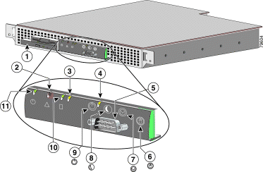
Figure 4-1 shows the system front-panel switches and indicators.

| 1 | CD-ROM drive | 7 | Reset switch |
| 2 | System-fault indicator | 8 | Sleep switch (not supported) |
| 3 | Ethernet 0 activity / link indicator | 9 | Power switch |
| 4 | Ethernet 1 activity / link indicator | 10 | Hard-drive indicator |
| 5 | Console / serial port | 11 | Power indicator |
| 6 | Non-maskable interrupt switch |
|
|
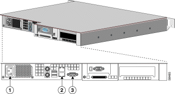
Figure 4-2 shows the system back-panel connections.

| 1 | AC power receptacle | 3 | Serial port |
| 2 | Ethernet connectors (Ethernet 0 is the lower port, and Ethernet 1 is the upper port) |
|
|
To check connections and switches, perform the following steps:
Step 1 Turn off the system, including any attached peripherals.
Step 2 Disconnect all the AC power cables from their electrical outlets.
Step 3 If the computer is connected to a power strip (or power distribution unit), turn the power strip off and then on again.
Step 4 Plug the power strip into another electrical outlet.
Step 5 Plug a different system into the electrical outlet.
Step 6 Reconnect the system to the electrical outlet or power strip. Make sure that all connections fit tightly together.
Step 7 Power on the system.
Step 8 Power off the system and all attached devices. Disconnect all the AC power cables from their electrical outlets.
Step 9 Reseat all power cables connected to the system, peripheral devices, and electrical outlets.
Step 10 Reseat the keyboard and mouse interface cable connectors, if present, in the proper connectors on the back of the system (see Figure 4-2).
Step 11 Reconnect the video-interface cable connectors, if present, to the video connector on the back of the system (see Figure 4-2) and to the connector on the back of the monitor.
 |
Note On some monitors, the video interface cable is permanently attached. |
Step 12 Check the network connections as instructed in "Troubleshooting the Integrated NICs."
Step 13 Power on the system and all attached devices.
Looking at and listening to the system is important in determining the source of a problem. Figure 4-3 shows the front-panel indicators. For a description of these indicators, see Table 4-1. Look and listen for the boot routine indications described in Table 4-2.

| 1 | CD-ROM drive | 7 | Reset switch |
| 2 | System-fault indicator | 8 | Sleep switch (not supported) |
| 3 | Ethernet 0 activity / link indicator | 9 | Power switch |
| 4 | Ethernet 1 activity / link indicator | 10 | Hard-drive indicator |
| 5 | Console / serial port | 11 | Power indicator |
| 6 | Non-maskable interrupt switch |
|
|
| Look/Listen for: | Then. . . |
|---|---|
An error message | See the "Messages and Codes" section. |
The diskette-drive access indicator | The diskette-drive access indicator should quickly flash on and off when you access data on the diskette drive. If the diskette-drive access indicator does not light up, contact the Cisco TAC. |
The hard-disk drive activity indicators | The hard-disk drive activity indicators should quickly flash on and off when you access data on the hard-disk drives. If the hard-disk drive access indicator does not come on, contact the Cisco TAC. |
A series of beeps | See the "System Beep Codes" section." |
Applications, operating systems, and the system itself are capable of identifying problems and alerting you to them. When a problem occurs, a message may appear on the monitor screen or a beep code may sound.
This section describes each type of message and lists the possible causes and actions you can take to resolve any problems indicated by a message. To determine what type of message you have received, read the following sections.
When an error that cannot be reported on the monitor occurs during a boot routine, the computer may emit a series of beeps that identify the problem. The beep code is a pattern of sounds; for example, two beeps close together is the code for a parity error. This information will be valuable to the Cisco TAC representative if you need to call for technical assistance.
 |
Note If the system boots without a given peripheral attached, the computer will not issue beep codes related to these peripherals. |
When a beep code is emitted, record it on a copy of the Diagnostics Checklist in the "Diagnostics Checklist" section and then look it up in Table 4-3. If you are unable to resolve the problem by looking up the meaning of the beep code, use the Diagnostics CD to identify a more serious cause. If you are still unable to resolve the problem, see the "Obtaining Technical Assistance" section, for instructions on contacting the Cisco TAC.
When you run a test group or subtest in the Diagnostics CD, an error message may result. These particular error messages are not covered in this section. Record the message on a copy of the Diagnostics Checklist, and then follow the instructions for contacting Cisco TAC in the "Obtaining Technical Assistance" section.
Unlike many diagnostic programs, the Diagnostics CD helps you check the system hardware without any additional equipment and without destroying any data. By using the Diagnostics CD, you can have confidence in the system operation. If you find a problem that you cannot solve by yourself, the diagnostic tests can provide you with important information you will need when talking to a Cisco TAC representative.
 |
Note Use the Diagnostics CD shipped with the Cisco CTE 1450 to test only Cisco CTE 1450 systems. If you use this program with other systems, incorrect system responses or error messages might result and the diagnostics functions may not work at all. |
The Diagnostics CD is a bootable CD that provides a series of menus and options from which you choose tests for particular device groups or devices. You can also control the sequence in which the tests are run. The diagnostic menus also have these helpful features:
Whenever a major component or device in the computer system does not function properly, you might have a component failure. As long as the microprocessor and the I/O components of the system (the monitor and keyboard connections and CD-ROM drive) are working, you can use the Diagnostics CD. If you know what component(s) you need to test, simply select the appropriate diagnostic device group(s) or subtest(s).
Contact Cisco TAC if using the Diagnostics CD becomes necessary. See the "Obtaining Technical Assistance" section for instructions on contacting the Cisco TAC.
You run the Diagnostics CD by inserting it in the CD-ROM drive, connecting a keyboard and mouse to the back panel, and rebooting the system. The diagnostic routines will load in place of the normal Cisco CTE 1450 operating software. Follow the prompts and menus to perform the desired tests, and refer to the online help as needed.
If you suspect that the problem is with a device connected to the serial port, perform the following steps:
Step 1 Turn off the system and any peripheral device connected to the serial port.
Step 2 Swap the interface cable that connects the device to the serial port with a known working cable.
Step 3 Turn off the system and the serial device, and swap the device with a comparable working device.
Step 4 Turn on the system and the serial device.
If you encounter problems with the system's integrated network interface card (NICs), the following actions may help you diagnose the problem:

You must remove the system bezel before installing or removing the system from the rack, installing or removing a hard-disk drive, or using the diskette or CD-ROM drive.
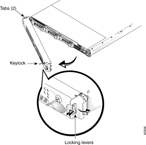
If the system key lock is locked, use the key to unlock. To remove the front bezel, press the tab on the right side of the bezel and remove the bezel from the chassis (see Figure 4-5).

To replace the front bezel, perform the following steps:
Step 1 Insert the tabs of the front bezel into the left side of the system.
Step 2 Ensure that the right locking lever is in the open/angle position and then close the bezel until the right side of the bezel snaps into place (see Figure 4-5).
Step 3 If the system key lock was locked before removal, use the key to relock the system.
This completes the bezel replacement procedure.
If the system was dropped or damaged while being moved, you should check the system to see if it functions properly. If an external device attached to the system is dropped or damaged, contact the manufacturer of the device for instructions or see the "Obtaining Technical Assistance" section for instructions on contacting the Cisco TAC.
![]()
![]()
![]()
![]()
![]()
![]()
![]()
![]()
Posted: Thu Dec 12 15:20:13 PST 2002
All contents are Copyright © 1992--2002 Cisco Systems, Inc. All rights reserved.
Important Notices and Privacy Statement.