|
|

The Cisco Content Transformation Engine 1400 (CTE 1400) Series devices are appliances used to render web-based content (such as HTML or XML) to a format appropriate for devices that do not accept HTML. Such devices include WAP phones, IP phones, or PDAs).
The Cisco CTE 1450 is a combined hardware and software platform, used in conjunction with CTE Design Studio (which defines the rendering rules for the CTE 1450). The details of the rendering process are defined in a GUI application (CTE Design Studio) as part of the Cisco CTE 1450 package. Because of its ease of deployment and the use of the GUI tool, the Cisco CTE 1450 allows content providers to quickly extend the reach of existing data.
This chapter includes a high-level description of the Cisco CTE 1450 and its features. It contains network application diagrams and a functional overview of the product.
 |
Note Throughout this guide, you will see the Cisco CTE 1400 Series devices referred to as the "Cisco CTE 1450" or as "your system." Some document titles refer to a Cisco CTE 1400 rather than a Cisco CTE 1450, but the software runs on both chassis. |
The Cisco CTE 1450 is a dedicated appliance that performs the following functions to deliver wireless data:
Figure 1-1 shows a simple Cisco CTE 1450 application.
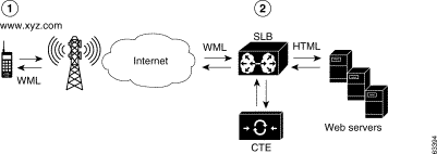
A Cisco CTE 1450 is typically installed behind an SLB and runs in reverse-proxy mode. To the SLB, the Cisco CTE 1450 appears to be a server with content (www.xyz.com). The Cisco CTE 1450 also appears to be a client when it makes a request for the real data residing on the content server. No IP address changes or software changes are required in the back-end servers. Users need to configure the SLB specifically for these services.
The Cisco CTE 1450 works with existing network infrastructure as a complete solution. For example, the Cisco CTE 1450 works with the SLB to provide load balancing for mobile traffic. Cookies ensure that users dropped due to intermittent connections can resume their sessions where they left off when they reconnect. The Cisco CTE 1450 can also work with caches to speed up service to mobile users.
The Cisco CTE 1450 product is composed of two parts:
The Cisco CTE 1450, which easily adapts to customer network configurations, supports four configuration modes. The modes differ mostly in regard to the device that the CTE 1450 is attached to, where the content comes from, and where the content is sent.
These modes are described in the following sections.
In SLB mode, a Cisco CTE 1450 farm and a farm of web servers connect to a combination switch/server load balancer. In this scenario, the Cisco CTE 1450s are configured just like servers in a server farm with a URL of www.xyz.com. As far as the SLB is concerned, each Cisco CTE 1450 is a server that can handle a request. Wired requests, such as Netscape Navigator or Internet Explorer, are load balanced over the server farm, while other requests, such as a wireless or IP phone, are sent to the Cisco CTE 1450s. Figure 1-2 shows an example of several Cisco CTE 1450s in SLB mode.
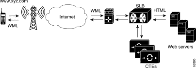
Each Cisco CTE 1450 contains the same configuration data and can serve any client request. If one Cisco CTE 1450 in the farm fails, the SLB balances connections to other Cisco CTE 1450s. By adding more Cisco CTE 1450s, the site can handle more wireless sessions.
In directed mode, the Cisco CTE 1450 and a web server connect to a switch rather than a switch/server load balancer combination. Traditional wired clients go to the site via the usual URL, www.wired.site.com, while wireless clients go to the site via a different URL, www.wireless.site.com. This URL maps to the Cisco CTE 1450. Figure 1-3 shows an example of a Cisco CTE 1450 in directed mode.

In direct mode, the Cisco CTE 1450 connects to a switch with a web server directly attached to the Cisco CTE 1450. All traffic is sent to the Cisco CTE 1450. Figure 1-4 shows an example of a Cisco CTE 1450 in direct mode.

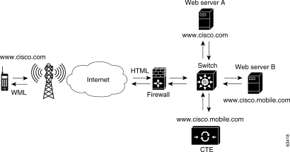
In redirect mode, the Cisco CTE 1450 connects to a switch with a web server directly attached. The wireless device makes a request for the same URL used by a wired device—www.site.com. Figure 1-5 shows an example of a Cisco CTE 1450 in redirect mode.
A script in Web server A checks the browser type and sends a redirect to the mobile device that points to the Cisco CTE 1450—www.mobile.site.com. The wireless device sends a request to www.mobile.site.com, and the Cisco CTE 1450 sends the request to Web server B.
The Cisco CTE 1450 provides the following features to users of non-HTML devices wishing to access HTML-format information:
The Cisco CTE 1450 also provides the following features to providers of HTML-format information:
All CTE software is loaded at the factory. The following software is included on your system:
Cisco does not support the presence of any third-party software on the Cisco CTE 1450. Installing third-party software on the Cisco CTE 1450 may void your support contract; Cisco will not support any technical difficulty arising from the installation of any third-party software package.
Multiple instances of the Cisco CTE 1450 in conjunction with an SLB can provide failover redundancy. In the event of a hardware or software failure, all current active requests will be lost; however, the next request will go to the failover Cisco CTE 1450, provided that the failover Cisco CTE 1450 contains the same configuration information as the primary Cisco CTE 1450.
Two 10/100 RJ-45 interfaces are provided for network connectivity. In addition, one console port is provided for configuration purposes.
The Cisco CTE 1450 has a bezel that attaches to its front and covers the front panel. The bezel covers the power switch and other front-panel features to prevent accidental power-down or reboot. The bezel contains two Ethernet indicators and a power indicator, and it provides access to the serial port. Indicators are also marked with icons that indicate their function.
You need to remove the bezel to turn on the unit after installation. To remove the bezel, press the tab on each end of the bezel and lift it from the chassis. Figure 1-6 shows the bezel features.
 |
Caution Do not grab the bezel when lifting the unit. The bezel is not intended as a handle and may not support the weight of the unit. |
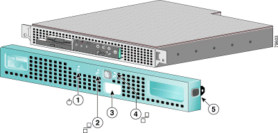
| 1 | Power indicator | 4 | Ethernet 1 activity / link indicator |
| 2 | Ethernet 0 activity / link indicator | 5 | |
| 3 | Console / serial port access |
|
|
The Cisco CTE 1450 front panel contains several Items not included on the bezel. These include switches, indicators, a CD-ROM drive, and a serial port. See Figure 1-7 for a complete list.
To access the front panel, remove the bezel (see the "Removing and Replacing the Bezel" section). Figure 1-7 shows the front panel's features.
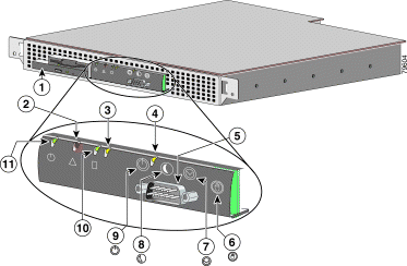
| 1 | CD-ROM drive | 7 | |
| 2 | 8 | Sleep switch (not supported) | |
| 3 | 9 | ||
| 4 | Ethernet 1 activity / link indicator | 10 | |
| 5 | Console / serial port | 11 | Power indicator |
| 6 | Non-maskable interrupt switch |
|
When troubleshooting your system, you might need to check the status of the indicators on the system front panel (see Figure 1-7). The appearance and function of these lights are described in Table 1-1.
Refer back to Figure 1-7 to see the location of the switches on the Cisco CTE 1450 front panel. To activate a switch, press the button with the corresponding icon on the front panel. Table 1-2 describes the function of these switches.
The back panel contains the Cisco CTE 1450 AC power receptacle, Ethernet connectors, and a serial port. Figure 1-8 shows the back-panel features. Do not attach peripheral devices, such as mice, monitors, and keyboards to the Cisco CTE 1450. It does not support their use.
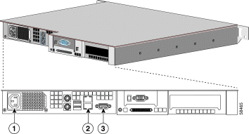
| 1 | AC power receptacle | 3 | |
| 2 | Ethernet connectors (Ethernet 0 is the lower port, and Ethernet 1 is the upper port) |
|
|
The two integrated serial ports on the front and back panels of the system use 9-pin, D-subminiature connectors.
If you reconfigure your hardware, you may need a pin number and signal information for the serial port connectors. Figure 1-9 illustrates the pin numbers for the serial port connectors, and Table 1-3 defines the pin assignments and interface signals for the serial port connector.

Your system has integrated 10/100 Mbps Ethernet connectors. Each Ethernet connector provides all the functions of a network expansion card and supports both the 10BASE-T and 100BASE-TX Ethernet standards.
The Cisco CTE 1450 Ethernet connectors are designed for attaching an unshielded twisted pair (UTP) Ethernet cable equipped with standard RJ-45 compatible plugs. Observe the following cabling restrictions for 10BASE-T and 100BASE-TX networks:
 |
Note To avoid line interference, put voice and data lines in separate sheaths. |
![]()
![]()
![]()
![]()
![]()
![]()
![]()
![]()
Posted: Thu Dec 12 15:15:19 PST 2002
All contents are Copyright © 1992--2002 Cisco Systems, Inc. All rights reserved.
Important Notices and Privacy Statement.