|
|

This chapter describes three mounting methods for positioning your VNS in a rack.The different mounting procedures are described in different sections. This chapter contains the following sections:
 | Caution Installation should be performed by authorized personnel only. |
You can flush mount the VNS into a 19- or 23-inch rack, or you can center mount it. For either mounting method, you need to allow enough clearance space at the front of the rack to enable removal and replacement of the VNS.
You can mount the VNS into a standard 19" rack (17.75" +0.12 and -0.00 inches between the rails), such as Cisco-supplied cabinet, which contains two front and rear mounting rails. The VNS has a front mounting flange and rear-mounting brackets that will align with the mounting rails.
To use a 23-inch rack for INS installation, you need to provide adapter brackets to adjust the width of the rack opening to 17.75 (+0.12 and -0.00) inches. Adapter brackets for installation of 19-inch equipment are commercially available.
The VNS can be mid-mounted by using the holes at the sides of the VNS chassis.
 | Caution The VNS is a single, enclosed unit and weighs approximately 60 lbs. Use two people when it is necessary to lift it into place. |
To rack mount the VNS-AC-E or VNS-DC-E, follow these steps:
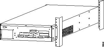
Step 1 From the front of the rack, slide the VNS-AC-E or VNS-DC-E into the rack and secure the holes in the front mounting flanges to the holes in the rack mounts.
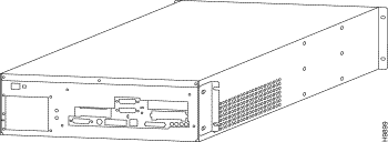
Step 2 From the rear of the rack, position the rear-mounting brackets, shown in Figure 4-1, on the outside of the VNS-AC-E or VNS-DC-E chassis.
Step 3 Loosely secure the rear-mounting bracket to the VNS-AC-E or VNS-DC-E chassis using the screws that were supplied.
Step 4 Secure the rear-mounting brackets to the rack's mounting posts.
Step 5 Tighten the four screws holding the rear-mounting brackets to the VNS-AC-E or VNS-DC-E chassis.

To mid-mount the VNS-AC-E or VNS-DC-E, follow these steps:
Step 1 Attach the mid-mount right-angle brackets to the VNS-AC-E or VNS-DC-E chassis using the mounting holes shown in Figure 5-5. (Make sure to use the same set of holes, either 4.5-inch or 10-inch, on each side.)

Step 2 From the front of the rack, slide the VNS-AC-E or VNS-DC-E into the rack until the Mid-Mounting brackets are up against the rack posts.
Step 3 Secure the holes in the Mid-mounting Right-Angle brackets to the holes in the rack mounts.
Step 4 From the rear of the rack, position the mid-mounting brackets on the outside of the VNS-AC-E or VNS-DC-E chassis.
Step 5 Loosely secure the rear-mounting bracket to the VNS-AC-E or VNS-DC-E chassis using the screws that were supplied.
Step 6 Secure the rear-mounting brackets to the rack's mounting posts.
Step 7 Tighten the four screws holding the rear-mounting brackets to the VNS-AC-E or VNS-DC-E chassis.

The redundant, or second VNS in a redundant pair, is rack mounted in the same rack as the IGX/IPX switch exactly like the first VNS. Figure 4-4 illustrates a redundant pair of VNS's in a typical rack.

|
|