|
|

Table Of Contents
Telephony Applications Using VISM
Telephony Applications Using VISM
This chapter describes how the VISM card is used in telephony applications to transport traditional TDM voice traffic as digitized voice traffic over ATM networks. The following topics are discussed:
•
"Tandem Switch Offloading" section
•
Tandem Switch Offloading
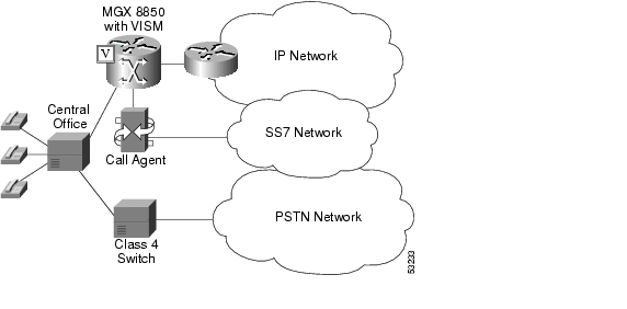
Figure 4-1 shows VISM used to offload a Class 4 tandem switch by transporting a portion of the voice traffic across an ATM network instead of the Public Switched Telephone Network (PSTN). VISM acts as the voice gateway in this application. Use VISM in the VoIP switching or switched AAL2 PVC operating mode to enable this application.
Figure 4-1 VISM Used in a Tandem Switch Offloading Application
When a call is initiated, the central office can use either the Class 4 switch or VISM to handle the call. When calls are passed to VISM, VISM backhauls the signaling to an MGCP compliant call agent. The call agent at the near end manages the call setup in conjunction with the call agent at the far end and the calling and called VISM cards.
Note
Each VISM card supports up to eight T1 or E1 lines for voice traffic. You can use an alternative method to connect the voice lines to the VISM cards—the TDM lines can be carried over a T3 line to an SRM card in the Cisco MGX shelf where the individual T1 lines are broken out and distributed to the VISM card internally.
For more information refer to the Cisco MGX 8850 (PXM1E/PXM45), Cisco MGX 8950, and Cisco MGX 8830 Hardware Installation Guide Release 2 through 4.
The VISM connects to the ATM network using either VoAAL2 or VoIP (UDP/IP packets encapsulated in AAL5 PVCs). VISM and the call agent communicate with each other and their activities are coordinated through MGCP.
For VoIP, when the call setup procedure is complete, each VISM has the IP address of the other VISM associated with the call. An end-to-end IP bearer circuit is established between the calling and called parties. At this point, the voice conversation can proceed.
By way of example, Figure 4-1 shows only one location for the VISM and call agent; in reality there is a similar arrangement for each tandem switch.
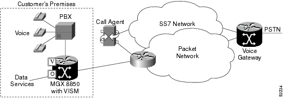
Figure 4-2 shows the connection from VISM to the call agent in greater detail.
Figure 4-2 VISM Used as a Voice Gateway Application
The VISM/MGX 8000 shelf is connected to the network by an OC-3 line which is used for both the voice payload and the communication with the call agent. A network edge router moves the voice traffic across the network to the called party's VISM and routes call control information between the VISM and the call agent.
For reliability, two PVCs using separate physical links to two separate edge routers to the packet network can be established. If the primary circuit fails, transmission automatically switches to the secondary circuit. For enhanced reliability, the physical OC-3 links to the network can be protected by the SONET APS feature.
Using all the available slots, the Cisco MGX 8850 (PXM1, PXM1E, and PXM 45) and the Cisco MGX 8250 can be configured with up to 24 VISM cards. The Cisco MGX 8230 and Cisco MGX 8830 can be configured with up to 8 VISM cards.
Multiservice Access
A Cisco MGX 8000 series shelf, combined with one or more VISM cards, provides multiservice access between a customer's TDM network and a voice gateway over a packet network. The voice gateway provides the interface to the telephone network.
When voice traffic is conveyed over a packet network using VISM and an MGX 8000 series shelf (multiservice access), the MGX 8000 series shelf is located either at the customer's premises or at the central office. Use VISM in the VoIP switching or switched AAL2 PVC operating mode to enable multiservice access.
Multiservice access is similar to the tandem switch offloading application, except that instead of performing as the voice gateway, VISM provides access to the voice gateway.
VISM operates in conjunction with an MGCP compatible call agent via an edge router/switch on the packet network. Signaling is backhauled from VISM to the call agent through this connection. The call agent connects to the SS7 network and handles call setup and teardown across the packet network. The VISM connects to the ATM network and handles the voice payload between the TDM voice/data network and a voice gateway. For transmitting the voice payload to the network, VISM uses either VoIP transported in AAL5 ATM cells or VoAAL2.
Other data services (such as Frame Relay) can also be accommodated by configuring the MGX 8000 series shelf with the appropriate service modules (for example, FRSM) and using separate PVCs into the packet network.
AAL2 Trunking
A Cisco MGX 8000 series shelf, in combination with VISM cards, provides AAL2 trunking between a voice TDM network and voice gateways over a packet network. Use VISM in the AAL2 trunking operating mode to enable this application.
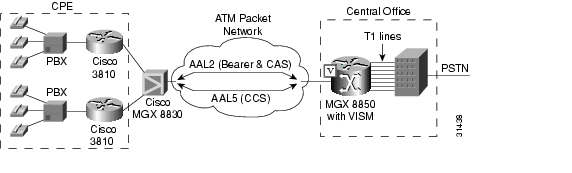
Figure 4-3 shows a trunk with a VISM-equipped MGX 8850 shelf at one end of a trunk (at the central office) and a Cisco 3810 Multiservice Access Concentrator and a Cisco MGX 8830 edge concentrator at the other end of the trunk (customer premises).
Figure 4-3 AAL2 Trunking—One End
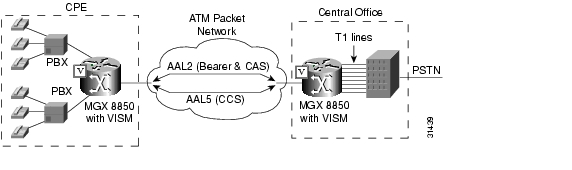
Figure 4-4 shows a trunk with a VISM-equipped MGX 8850 shelf at each end of the trunk.
Figure 4-4 AAL2 Trunking—Two Ends
Note
In Figure 4-3 and Figure 4-4, the trunk is an AAL2 non-switched ATM PVC that carries the voice traffic. The voice traffic is delivered to, or received from, the central office over short-haul T1 lines.
If CAS signaling is used, the signaling is transported across the trunk as AAL2 type 3 cells.
If CCS signaling is used, the signaling is delivered across the ATM network as AAL5 cells over separate PVCs. VISM supports up to eight AAL5 PVCs, one for each T1/E1 line.
Other data services (such as Frame Relay) can be accommodated by configuring Cisco 3810 or Cisco MGX 8000 hardware with the appropriate service modules and using separate PVCs into the packet network. The packet network routes these other data services as required.
In AAL2 trunking mode, VISM is not involved with a call agent and the functions of call control. Multiple calls can be transported over a single PVC using the AAL2 channel identifier (CID) mechanism. DS1/DS0s are bound to virtual channel identifier (VCI)/CIDs so that voice traffic from any particular DS0 is automatically passed to its bound VCI/CID (and vice versa).
![]()
![]()
![]()
![]()
![]()
![]()
![]()
![]()
Posted: Thu Jun 10 16:51:46 PDT 2004
All contents are Copyright © 1992--2004 Cisco Systems, Inc. All rights reserved.
Important Notices and Privacy Statement.