|
|

Table Of Contents
VISM/VISM-PR Functional Description
Echo Cancellation, Voice Compression, A/Mu Law Conversion
Voice Activity Detection and Silence Suppression
CAS Processing in VoIP Switching and Switched AAL2 PVC Operating Modes
CCS Processing in Switched AAL2 PVC Operating Mode
CAS Processing in AAL2 Trunking Operating Mode
CCS Processing in AAL2 Trunking Operating Mode
ATM Voice Data Processing Function
Transporting Voice Cells with VoIP
Transporting Voice Cells with Switched AAL2 PVC
Transporting Voice Cells with AAL2 Trunking
Transporting Voice Cells with Switched AAL1 SVC
xGCP Extensions for AAL2 Switched PVC and AAL2 SVC Operating Modes
Embedded VISM/VISM-PR Management Functions
VISM/VISM-PR Functional Description
The functions performed by VISM/VISM-PR are described in the following sections:
•
"TDM Line-Handling Function" section
•
•
•
•
•
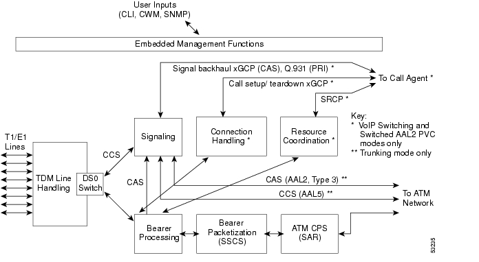
Figure 5-1 shows the functional blocks of VISM/VISM-PR. Items with single asterisks indicate VoIP switching and switched AAL2 PVC functions. Items with double asterisks indicate AAL2 trunking functions. Items without asterisks indicate VoIP switching, switched AAL2 PVC, and AAL2 trunking functions.
Figure 5-1 VISM /VISM-PR Detailed Functional Blocks
TDM Line-Handling Function
The TDM line-handling function provides the physical layer interface to the T1/E1 lines and handles the following features:
•
•
•
•
•
•
Outgoing traffic—in from the TDM network and out to the packet network—is processed by the T1/E1 framers where each DS0 is extracted from its DS1 stream and is routed by a DS0 switch to the appropriate function. Bearer DS0s are routed to the bearer processing function. CCS signaling DS0s are routed to the TDM signaling function.
Outgoing traffic—in from the packet network and out to the TDM network—is processed in the opposite manner. The DS0s received from the ATM side are inserted into their respective DS1s and transmitted over the appropriate line in the TDM network.
Bearer Processing Function
The bearer processing function processes raw bearer DS0 streams from the T1/E1 lines in preparation for packetization and segmentation and reassembly (SAR) processing on the ATM side. Most of the bearer processing is performed by the VISM/VISM-PR daughter card's DSPs.
The main processing categories are
•
•
•
Echo Cancellation, Voice Compression, A/Mu Law Conversion
Bearer DS0 streams are received from the T1/E1 line function, and each is assigned to a DSP configured for echo cancellation (ECAN). You can configure the following ECAN parameters:
•
•
•
If voice compression is required, the ECAN voice streams are assigned to a second DSP configured with the required codec. Available compression schemes are:
•
•
•
•
•
•
•
•
•
•
•
VISM/VISM-PR allows the use of codec templates in which the user selects a template instead of specifying each allowable codec individually. VISM/VISM-PR supports the following codec templates:
•
•
•
•
•
Within each template, you can specify a preference order for each codec. At call setup time, the codec to be used from the configured template is either specified by the call agent or negotiated between the calling and called VISM/VISM-PR cards. If the codec is negotiated, the most preferred codec that both VISM/VISM-PR cards can support is selected.
For each codec, VISM/VISM-PR supports various packetization periods as described in Table 5-1.
Voice Activity Detection and Silence Suppression
You can configure the VISM/VISM-PR card DSPs to monitor the TDM voice stream for voice activity. If the voice activity detection (VAD) feature is enabled and no voice activity (silence) is detected for more than a specified period of time, typically 250 ms, the silent voice samples are suppressed. During periods of silence, parameters defining background noises transmit periodically. You can configure the remote VISM/VISM-PR to use the background noise information to generate comfort noise at the called end while silence suppression is in operation.
Fax and Modem Tone Detection
You can configure the VISM/VISM-PR card DSPs to detect the modem or fax tones on the data lines. For VoIP operating mode, the action is specified using command line interface (CLI) commands. See Chapter 7, "CLI Commands," for more information on CLI commands. For AAL2 connections, the action is specified in the AAL2 profile. Generally, when a modem or fax tone is detected, VAD and ECAN are turned off, and codec is changed to the specified type (for example G.711 or clear channel).
Note
Jitter Control
The VISM/VISM-PR card uses voice buffers on the DSP to reduce jitter on outgoing voice streams. Jitter control operates in the following modes:
•
•
CAS Handling
In applications using CAS, you can configure the VISM/VISM-PR card DSPs to monitor incoming traffic and extract the following CAS signaling information:
•
•
•
You can configure VISM/VISM-PR to handle various CAS variations such as immediate start, wink start, ground start. The extracted CAS signaling information is sent to the TDM signaling function.
Signaling Function
All TDM signaling enters and exits VISM/VISM-PR on the T1/E1 lines and is directed to the signaling function. CAS signaling information is received from the bearer processing function, described in the "Bearer Processing Function" section. CCS signaling information arrives directly from the TDM line handling function, described in the "TDM Line-Handling Function" section.
VISM/VISM-PR depends on a combination of the following two features to determine how to handle signaling:
•
–
–
–
–
–
–
–
•
–
–
Signaling enters from the T1/E1 lines and, depending upon the mode and the type of signaling, is processed for the correct protocol and directed to either the call agent or the ATM trunks (see Figure 5-2).
Note
Figure 5-2 VISM /VISM-PR Signaling Paths
CAS signaling can be configured, in the switched AAL2 PVC operating mode to send the signaling to the call agent or over an AAL2 PVC as in the AAL2 application.
CAS Processing in VoIP Switching and Switched AAL2 PVC Operating Modes
In the VoIP switching and switched AAL2 operating modes, CAS signaling is processed by the call agent using xGCP protocols.
The call agent performs the following functions:
•
•
The VISM/VISM-PR card performs the following functions:
•
•
•
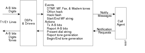
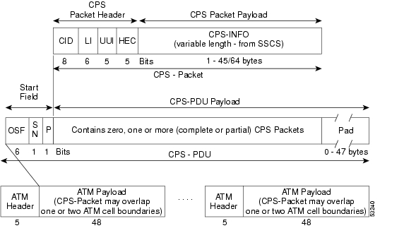
Figure 5-3 shows the messages involved in CAS processing with the VoIP switching and switched AAL2 PVC operating modes.
Figure 5-3 CAS Processing—Message Structure
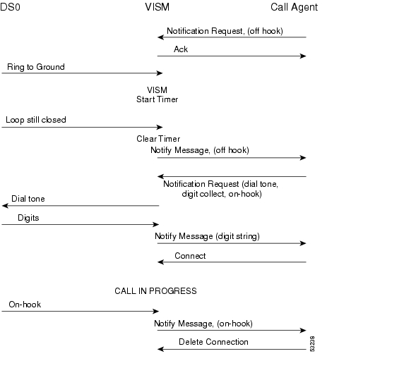
Figure 5-4 shows the local CAS processing call setup message sequences which occur between VISM/VISM-PR, the call agent, and the telephone equipment on the DS0.
Figure 5-4 CAS Signaling in Initiating and Terminating a Call
Note
The call processing for the VoIP switching and switched AAL2 operating modes is described in the following list:
1.
2.
3.
4.
5.
6.
CCS Processing in Switched AAL2 PVC Operating Mode
In the switched AAL2 PVC operating mode, CCS signaling can be configured to pass (backhaul) CCS signals between the user PBXs and the call agents.
You can configure T1 and E1 lines for CCS signaling. You must specify a particular DS0 as an Integrated Services Digital Network (ISDN) D channel to carry the Primary Rate Interface (PRI) signaling. Signaling from the private branch exchange (PBX) is received on the D channel as level 3 Q.931 messages encapsulated in the information field of level 2 Q.921 LAPD information frames.
The Q.921 link is terminated at the VISM/VISM-PR and on the call agent side. A Redundant User Datagram Protocol/User Datagram Protocol/Internet Protocol (RUDP/UDP/IP) connection is used to carry level 3 Q.931 signaling between VISM/VISM-PR and the call agent. This link to the call agent flows through an intermediate router. From VISM/VISM-PR to the router, the RUDP/UDP/IP packets are segmented and transported as AAL5 ATM cells.
The function of the VISM/VISM-PR PRI/backhaul feature is to pass the Q.931 messages between the PBX and the call agent.
VISM handles all Q.921 frame types. For information type frames, the process is described in the following list:
1.
2.
3.
4.
In CCS processing, communication between VISM/VISM-PR and the call agent involves both call control information using xGCP protocols and CCS signaling using Q.931 protocol. Both are transported using the AAL5 ATM connection.
Signaling from the call agent to the PBX is handled in the same manner but in reverse:
1.
2.
VISM/VISM-PR is not involved with the signaling content but acts as an interface between the PBX and the call agent.
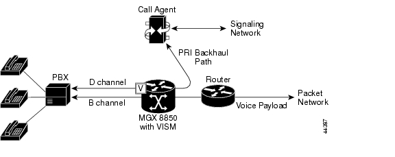
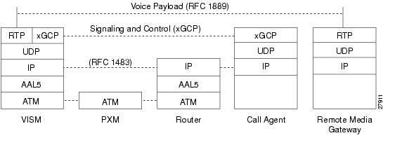
Figure 5-5 shows the VISM/VISM-PR PRI/backhaul process.
Figure 5-5 PRI/Backhaul Path
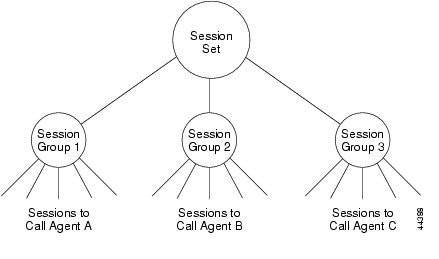
For RUDP links between VISM/VISM-PR and the call agents, use a session with a session manager.
A session represents a single RUDP link to a specified call agent. Sessions are organized into session groups, and session groups are organized into session sets. VISM/VISM-PR architecture supports up to 64 sessions and up to 16 session groups.
Multiple RUDP links for a specified call agent are set up as sessions in a single group. A group is required for each call agent for which CCS signaling is to be backhauled. Within a group, each session is assigned a priority level. When an active session fails, the session manager switches to the next highest priority backup session within the group. Figure 5-6 shows the hierarchy of RUDP sets, groups, and sessions .
Figure 5-6 RUDP Session Hierarchy
VISM/VISM-PR maintains a set of counters for the collection of statistics at both the Q.921 and Q.931 protocol levels. The collected statistics include the number of frames/packets/bytes sent and received, the number of resets, the number of discards and retransmissions, etc. See the CCS session and LAPD display commands in Chapter 7, "CLI Commands," for more information on collected statistics for the CCS session and LAPD display commands.
Use the CLI PRI/backhaul commands to do the following:
•
•
•
•
See Chapter 7, "CLI Commands," for more information on CLI commands.
CAS Processing in AAL2 Trunking Operating Mode
CAS signaling is extracted from the voice data and is transported across the packet network in AAL2 trunking operating mode. The signaling is transported across the same trunk (VC) and the same channel identifier (CID) as its associated voice stream, using AAL2 Type 3 messages in accordance with ITU-T I.366.2. The messages are used for CAS (A,B,C, and D) robbed bits, fax/modem tones, and digits and are transported with triple redundancy.
CCS Processing in AAL2 Trunking Operating Mode
CCS signaling is maintained as Q.931 messages and transported across the packet network using an AAL5 PVC in AAL2 trunking operating mode. The local and remote ends of the PVC are the same as those for the AAL2 PVC trunk carrying the associated voice data.
ATM Voice Data Processing Function
The VISM/VISM-PR DSPs process incoming voice data (for compression, ECAN, and so forth), and the data is prepared for transport over the ATM network. Voice samples are processed into ATM packets and then into ATM cells in preparation for transport. VISM/VISM-PR then transports the cells to Voice over ATM (VoATM) networks with the following supported operating modes:
•
•
•
•
Transporting Voice Cells with VoIP
The VoIP switching operating mode processes voice cells in the following order to transport them over ATM networks:
1.
Note
2.
3.
4.
Figure 5-7 shows the protocol stack for VoIP.
Figure 5-7 VoIP Protocol Stack
Figure 5-8 shows how a voice sample is packetized and transmitted as cells.
Figure 5-8 VoIP Cell Packetization and Transmission
At the layer containing RTP, a 12-byte header is added to the 80 bytes of packetized PCM. At the layer containing UDP, an 8-byte header is added. At the layer containing IP, a 20-byte header is added for a total of 120 bytes.
At the layer containing AAL5, the 8-byte AAL5 trailer is added and the data is padded with 16 bytes to make an integral number of ATM cell payload bytes. The resulting protocol data unit (PDU) is 144 bytes in length and is transported in three ATM cells.
A single PVC is set up between the Cisco MGX 8000 series platform and the router. All packets are sent across the PVC regardless of their destination. The router extracts the IP addresses and routes the cells accordingly.
To improve reliability, VISM/VISM-PR supports two independent OC-3 interfaces, each connected to a separate edge router and each with its own PVC. One PVC is designated the primary PVC and the other the secondary PVC. The primary circuit is used unless it fails, in which case VISM/VISM-PR switches automatically to the secondary circuit. Switchover may cause a temporary 250 ms delay on the lines.
VISM/VISM-PR communicates with the packet network about transmitting the voice payload by using the SONET OC-3 port on the MGX 8000 series platform PXM card. Voice payload samples are formatted and sent across the MGX 8000 series platform cellbus and onto the SONET connection.
Transporting Voice Cells with Switched AAL2 PVC
The switched AAL2 PVC operating mode transports voice cells with up to 64 PVCs. Multiple calls can share a single AAL2 connection simultaneously using a CID. Each PVC is assigned a virtual connection circuit identifier (VCCI). The VCCI/CID to endpoint/DS1/DS0 binding is made dynamically by the call agent as part of the call setup procedure. However, you can permanently set the binding, which makes VISM/VISM-PR operate as if it were in AAL2 trunking operating mode.
The AAL2 PVC supports AAL2 profiles and mid-call upspeeds. Codec changes can be supported if they are within the agreed upon profile. The following AAL2 profiles are supported:
•
•
•
•
•
•
•
Figure 5-9 shows the packetization process for AAL2 cells.
Figure 5-9 AAL2 Cell Packetization and Transmission
Transporting Voice Cells with AAL2 Trunking
The AAL2 trunking operating mode transports voice cells with up to 64 AAL2 trunks. The CID/virtual channel identifier (VCI) for each DS1/DS0 pair is preprovisioned, which ensures that DS0 voice streams are automatically transported over the appropriate trunk.
For CAS applications, voice cells and CAS signaling are transported across the AAL2 trunk. If a channel is configured for CCS signaling, the signaling is transmitted by extracting HDLC frames and forwarding them over preprovisioned AAL5 virtual circuits (the voice cells are still transmitted using AAL2).
VISM/VISM-PR does not support any call control functions with the AAL2 trunking operating mode. VISM/VISM-PR passes signal traffic across the trunk.
Alarm and packetization handling are the same as in the switched AAL2 PVC operating mode. See the "Transporting Voice Cells with Switched AAL2 PVC" section.
Transporting Voice Cells with Switched AAL1 SVC
VISM/VISM-PR interacts with a call agent using an xGCP protocol over AAL5 control PVCs. In the switched AAL1 SVC operating mode, the bearer path is VoAAL1, and the bearer connections are SVCs. VISM/VISM-PR dynamically sets up and tears down bearer connections.
Call Control Function
Call control is used in the VoIP switching and switched AAL2 PVC operating modes and is managed by the call agents. The call agent performs the following functions:
•
•
•
•
•
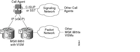
These functions require call agent communication with the VISM/VISM-PR cards under call agent control and peer call agents. Figure 5-10 shows the call agent communications links.
Figure 5-10 Call Agent Communications Links
The interface between the call agent and VISM cards is a gateway call control protocol generically known as xGCP. The following gateway call control protocols are supported:
•
•
•
•
SRCP enables the VISM card and the call agent to resynchronize. Synchronization occurs when the call agent first assumes control of VISM or after the call agent loses communication with VISM.
All protocols use a UDP/IP connection between the call agent and the VISM cards. The IP address of the call agent can be resolved in the following ways:
•
•
You can configure VISM/VISM-PR to use the internal table and external DNS in the following ways:
•
•
•
•
VISM/VISM-PR supports up to 11 domain names. Each domain name can have up to eight internal and eight external IP addresses.
Note
The interface between the call agent and other call agents is either Signaling System 7 (SS7) or a Cisco extended ISDN User Part (C-ISUP).
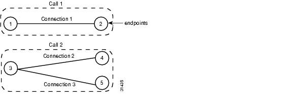
Connection Model
SGCP and MGCP gateway call control protocols assume a connection model where the basic constructs are connections and endpoints. Figure 5-11 shows a basic connection model.
Figure 5-11 Connection Model
Connections are grouped into calls. One or more connections can belong to the same call. Several connections, that may or may not belong to the same call, can terminate in the same endpoint.
The SGCP consists of the following commands:
•
•
•
•
•
The MGCP extends SGCP to include the following commands:
•
•
•
•
•
The TGCP command set is the same as the MGCP command set.
xGCP Extensions for AAL2 Switched PVC and AAL2 SVC Operating Modes
VISM/VISM-PR supports the following extensions to the xGCP protocols for AAL2 switched and AAL2 SVC applications:
Note
•
–
–
–
–
–
•
–
–
–
–
–
•
–
–
–
•
Endpoint Service States
Endpoints exist in one of two service states—in-service (IS) and out-of-service (OOS). The state of an endpoint is determined by user configuration commands and line alarm conditions. When an endpoint is added, it automatically assumes the state of the line.
When endpoints are taken OOS, the transition can be graceful or forced. If graceful, no new connections are permitted while ongoing connections are allowed to terminate normally. If forced, no new connections are permitted and all ongoing connections are terminated immediately.
You can also bring an endpoint to the IS and OOS states with the following commands, which operate either on a line-by-line basis or on the entire VISM/VISM-PR card:
•
•
•
•
These commands allow you to specify either a graceful or forced transition.
If an alarm condition on a line is raised, all endpoints on the line are brought into a forced transition to OOS. An automatic return to IS is performed when the alarm is cleared, unless a specific OOS command is executed in the meantime.
Restart In Progress Command
The call agent is kept informed of the state of all endpoints with the xGCP Restart In Progress (RSIP) command. The following minimum requirements must be met for this process to operate:
•
•
The VISM/VISM-PR card issues an RSIP command in the following situations:
•
–
–
–
–
•
–
–
•
–
–
•
Note
When the states of multiple endpoints are changed simultaneously, the VISM/VISM-PR card minimizes the number of RSIP commands through the use of the wildcard ( * ) convention of naming endpoints.
When an RSIP is sent to call agents, VISM/VISM-PR expects an acknowledgment. If no acknowledgment is received after a timeout period, the RSIP is sent again. This process is repeated a number of times, after which, if no acknowledgment is received, an acknowledgment is assumed.
You can configure both the timeout period and the number of retries with the cnfxgcpretry command.
Connection Admission Control
The VISM/VISM-PR connection admission control (CAC) feature calculates the effect of a new call on the bandwidth utilization of the ATM PVC before a new call is either admitted or rejected.
Each call requires a connection between two endpoints and requires a certain amount of bandwidth. Bandwidth is expressed as cells per second (cps) and depends upon the following:
•
•
•
CAC maintains a table of all currently active calls and their bandwidth requirements. When a new call is requested, CAC calculates the total bandwidth requirements of all the current calls and adds the bandwidth required by the newly requested call. The new total is then compared with the preprovisioned bandwidth (cps) of the ATM PVC.
If the new bandwidth total exceeds the preprovisioned bandwidth of the PVC, the call request is rejected. If the new bandwidth total is less than or equal to the preprovisioned bandwidth of the PVC, the call is accepted.
You can specify the values of the following VAD parameters in the CAC algorithm:
•
•
VAD parameter specification allows the CAC algorithm to take into account the bandwidth savings of VAD and improves the CAC decision-making process. You can specify the values of these parameters at the card level and at the logical channel level. The default condition is for CAC to be enabled.
Embedded VISM/VISM-PR Management Functions
VISM/VISM-PR management tools allow you to do the following:
•
•
•
•
Use any of the following tools to manage and configure the VISM/VISM-PR card:
•
•
•
Figure 5-12 shows an example of a CWM VISM Card Config screen with the card elements displayed.
Figure 5-12 VISM Card Config Screen—Card Elements Display
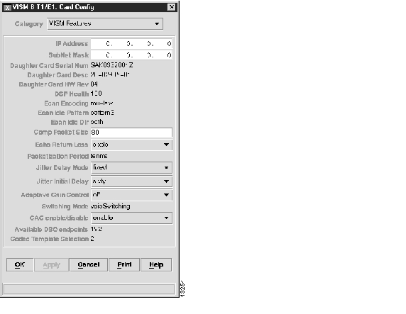
Figure 5-13 shows an example of a CWM VISM Card Config screen with the VISM features displayed.
Figure 5-13 VISM Card Config Screen—VISM Features Display
Refer to the WAN CiscoView for the MGX 8250 for more information on using CWM.
All three VISM management tools allow you to access and manipulate the VISM/VISM-PR Management Information Bases (MIBs) that contain all VISM/VISM-PR configuration settings, operating modes, and statistics.
![]()
![]()
![]()
![]()
![]()
![]()
![]()
![]()
Posted: Thu Jun 10 16:48:31 PDT 2004
All contents are Copyright © 1992--2004 Cisco Systems, Inc. All rights reserved.
Important Notices and Privacy Statement.