|
|

System management screens configure the overall parameters of an Cisco MGX 8260 node and define its interactions with other nodes and servers.
Before you can configure the Cisco MGX 8260, you must log on as a user with the privilege to change system parameters. You need SuperUser privileges to change most system-level settings.
To log on, follow these steps:
Step 1 Launch your web browser.
Step 2 Connect to the MGX 8260 HTTP server using the conventional http:// notation. You need to know the host name or IP address for the desired MGX 8260 node.
Step 3 The logon screen is displayed.
Step 4 In the User Id field, type your user name. On a new system, use SuperUser.
Step 5 In the Password field, type your password. On a new system, use cisco or the new password you assigned to this account.
The Cisco MGX 8260 displays the chassis view (see Figure 2-1).
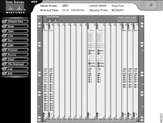
Step 6 From the Navigation pane on the left, select the operation you want to perform. To set node parameters click Node and then click a submenu item.
See the following sections for configuration tasks for nodes:
To view or change general system parameters, follow these steps:
Step 1 On the Navigation pane, click Node.
Step 2 Click System.
Three System Configuration forms opens.
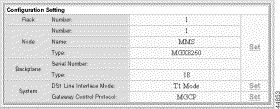
Step 3 In the Rack, Node, and Backplane section of the Configuration Settings form, click Set.
The System Configuration Setting screen opens:

Step 4 Enter the rack and node information in the System Configuration Settings form.
| Parameter | Description |
|---|---|
Rack Number | The rack number of this shelf |
Node Name | The name of this node. Enter up to 15 characters |
Node Number | The node number of this shelf |
Node Type | The node type—MGX 8260 |
BackPlane Serial Number | The backplane serial number |
BackPlaneType | The MGX 8260 backplane type |
Step 5 Click Modify, and then go back to the Configuration Setting form.

Step 6 In the DS1 Line Interface Mode section, click Set.
The System Ds1 Line Interface Mode Setting screen appears:

Step 7 Specify the interface mode for the chassis.
| Parameter | Description |
|---|---|
T1 | The T1 mode of operation for the chassis. You can't change to T1 if there are any E1 lines configured. |
E1 | The E1 mode of operation for the chassis. You can't change to E1 if BSCs are installed or DS1 lines are configured. |
 |
Warning Changing the interface mode interrupts service. Perform this operation during light traffic periods or during a pre-arranged maintenance window. |
Step 8 Click Modify.
After changing the interface mode, the node automatically resets.
Step 9 Login, and repeat steps 1 and 2.
Step 10 In the System section of the Configuration Setting screen, click Gateway Control Protocol.
The System Gateway Control Protocol Setting screen appears:

Step 11 Specify the communication protocol for call control.
| Parameter | Description |
|---|---|
MGCP | Use MGCP to communicate with a MGC (also known as Soft Switch). |
IPDC | Use IPDC to communicate with a MGC (also known as Soft Switch). |
 |
Warning Changing this protocol mode interrupts service. Perform this operation during light traffic periods or in a pre-arranged maintenance window. |
Step 12 Click Modify. The system applies the changes.
After changing the protocol for the gateway, the node automatically resets.
To view or change system group parameters, follow these steps:
Step 1 On the Navigation pane, click Node.
Step 2 Click System.
The three System Configuration forms open, one of which is the System Group Setting form used in this procedure.

Step 3 Click Set on the System Group Setting form.
The System Group Setting form is redisplayed with several text boxes.

| Parameter | Description |
|---|---|
Description | The model designation of the Cisco MGX 8260 hardware |
Object Identification | A unique identifier of the network management subsystems supported. This value is allocated within the SMI enterprises subtree (1.3.6.1.4.1) and provides an unambiguous means for management applications to identify the MGX 8260 and its capabilities. |
Up Time | The length of time this Cisco MGX 8260 has been in service |
Contact | The name of the system administrator |
Name | A user-defined description of the system |
Location | The physical location of the MGX 8260 chassis |
Services | The OSI layer that the MGX 8260 supports. |
Step 4 Enter new values.
Step 5 Click Modify. The system applies the changes.
Step 6 Go back to the System Configuration forms, and go to the next procedure.
To view or change the time, follow these steps:
Step 1 On the Navigation pane, click Node.
Step 2 Click System.
The three System Configuration forms open, one of which is the Time Setting form used in this procedure.

Step 3 Click Set on the Time Setting form.
The System Time Setting form is displayed.

| Parameter | Description |
|---|---|
Time Zone | Time zone, expressed as the number of hours before or after GMT1 (see Table 2-1) |
Date | The system date, specified in month (mm), date (dd), and year (yyyy) fields |
Time | The current time, set in hour, minute, and second fields |
| 1GMT = Greenwich Mean Time |
Step 4 Enter new values.
Step 5 Click Modify. The system applies the changes.
To view the HTML version, follow these steps:
Step 1 On the Navigation pane, click Node.
Step 2 Click System.
The three System Configuration forms open, one of which is the HTML form.
Step 3 View the HTML version number.
You configure the MGX 8260 management interface for local or remote operation by setting the appropriate IP addresses and management paths. Assign management IP addresses for each of the following management interfaces that you plan to use:
 |
Note If you change the IP address of the port the WebViewer is using, you will interrupt the session. |
To view and change management interface parameters, follow these steps:
Step 1 On the Navigation pane, click Node.
Step 2 Click Management IP.
The Management IP Settings form opens, displaying existing settings.

Step 3 Interpret the information as follows:
| Displayed Information | Description |
|---|---|
Management Gateway IP Address | The gateway for IP traffic to this node |
Management Ethernet Mac Address | The MGX 8260 MAC address |
Management IP1 | The IP address and mask for the 10BaseT port, expressed in standard IP dot notation |
In-band Management | The IP address and mask for the inband management virtual port, expressed in standard IP dot notation |
Management IP2 | The IP address and mask for the second 10BaseT port, expressed in standard IP dot notation, for redundant management networks. |
Step 4 Click Set to modify a management IP setting.
A Management Ethernet IP Setting form, such as the following one, or a similar form for setting the In-Band IP appears.

Step 5 Enter new values.
Step 6 Click Modify. The system applies the changes.
This section describes the process of configuring IP routes for the management interfaces.
To view all IP routes, follow these steps:
Step 1 On the Navigation pane, click Route.
Step 2 Click IP Route Setup.
The IP Route screen opens:
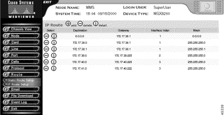
Step 3 To view detail information about a route, and click the I icon on the desired row.
The IP Route Information form opens:
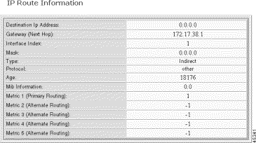
Step 4 Interpret the information as follows:
| Displayed Information | Description |
|---|---|
Destination | The destination IP address. Destination 0.0.0.0 is the default route. |
Gateway | The gateway, or next hop, for the route. This can be the address of the Ethernet or in-band management ports. |
IF | The interface identifier: 1—Primary Ethernet port 2—Secondary Ethernet port 3—In-band path |
Mask | The subnet for the route. |
Type | The type of route, such as direct or indirect. |
Protocol | The protocol type, such as local or other. |
Age | The age of the route is seconds. |
Mib Information | The version of the MIB associated with the interface. |
Metric 1-5 | The primary and alternate route metrics. These are specific to the protocol type, but -1 indicates not used. |
To add a static route, follow these steps:
Step 1 On the IP Route screen, click the + icon.
The Add IP Route screen opens:

Step 2 Enter the IP Address of the destination.
 |
Note Destination 0.0.0.0 is the default route. |
Step 3 Enter the mask.
Step 4 Click Add.
The system adds the IP route to the routing table.
To delete an IP route, follow these steps:
Step 1 On the Navigation pane, click Route.
Step 2 Click IP Route Setup.
The IP Route screen opens:

Step 3 Locate the IP Route that you want to delete in the list of routes, and click the - icon on that row.
Step 4 Click Delete.
The IP route is deleted the network.
To view information about an IP route, follow these steps:
Step 1 On the Navigation pane, click Route.
Step 2 Click IP Route Setup.
The IP Route screen opens:

The MGX 8260 clock module has three synchronization options:
You assign one clock source as the primary source and another as the secondary source. When using the line clock source, specify both the line and slot associated with the source.
During normal operation, the primary clock is the active source and the secondary clock is the backup source. If the active source fails, the Cisco MGX 8260 switches to the backup clock and reports an alarm. You can also switch to the backup source manually. This section explains how to set primary and secondary clocks and view clock status.
The clock parameters include:
To view or change clock source information, follow these steps:
Step 1 On the Navigation pane, click Node.
Step 2 Click Clock Source.
The Clock Source screen opens.

Step 3 Interpret clock settings as follows:
| Setting | Description |
|---|---|
Current Clock | The current clock source:
|
Current Clock Stratum | The level of Stratum clock:
|
Master Clock | The master clock source:
|
Clock Source Card Type | The type of clock source:
|
Primary and Secondary Clock Source Slot | The slot supplying the clock. This argument is ignored if the clock source type is external (BITS) or internal. Valid entries: 1 to 16 |
Primary and Secondary Clock Source Line | The line number for the clock source. This argument is ignored if the clock source type is external (BITS) or internal. Valid entries:
|
Primary and Secondary Clock Source Type | The clock source type:
|
Primary and Secondary Clock Status | The clock status:
|
 |
Note The selected clock source may not be the active clock source if the selected clock fails. |
Step 4 Click Set to modify the clock source.
The Primary Clock Source Setting form, or the corresponding form for setting the secondary clock, appears.
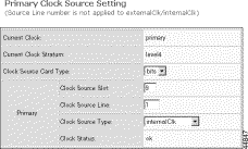
Step 5 Specify new settings, using the following table as a guide:
| Source | Slot | Line | ClkSrcType | ClkSrcCardType |
|---|---|---|---|---|
DS3 line | BSC: 11 to 16 | BSC DS3 lines: 501 to 506 | BroadBandClk | Optional |
DS1 line | NSC: 1 to 8, 11-16 | NSC DS1 lines: 1 to 16 | NarrowBandClk | Optional |
Bits input | 9 | Optional1 | ExternalClk | BITS |
SONET line | 9 | SCC, OC3 type: 1 to 4 | ExternalClk | OC3 |
Internal | 9 | Optional | InternalClk | Optional |
| 1Optional settings are ignored, but they must be valid entries. |
Step 6 Click Modify.
The system updates the clock settings.
You can force the system to switch between the primary and secondary clock. During normal operation, the current clock is the primary clock. Typically you switch clocks to restore the primary clock source after an automatic switchover to the secondary clock.To switch to the secondary clock, follow these steps:
Step 1 On the Navigation pane, click Node.
Step 2 Click Clock Source.
The Clock Source screen opens.
Step 3 On the Clock Source screen, click Switch Clock Source and confirm your action.
When managing the Cisco MGX 8260 from a SNMP manager, security is enforced with password-like community strings. SNMP communities are groupings of workstations and servers (or gateways) that can manage the Cisco MGX 8260. Community strings are important when managing the Cisco MGX 8260 from a Network Management System, like HP Openview. You can configure up to 15 community strings.
To view all community strings, follow these steps:
Step 1 On the Navigation pane, click Node.
Step 2 Click SNMP.
Step 3 From the SNMP options, click Community String.
The Community String screen opens.
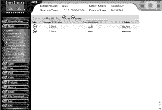
Step 4 Interpret the table as follows:
| Table Entry | Description |
|---|---|
Manager IP Address | The IP address of the manager associated with this string |
Community String | The name of the community string |
Privilege | The manager's privilege, either read-write or read-only |
To add a community string, follow these steps:
Step 1 On the Navigation pane, click Node.
Step 2 Click SNMP.
Step 3 From the SNMP options, click Community String.
The Community String screen opens.
Step 4 Click the + icon.
The Add Community String form opens.

Step 5 Enter the following parameters:
| Parameter | Description |
|---|---|
Manager IP Address | The IP address of an SNMP manager, expressed in standard IP dot notation. When set to 0.0.0.0, the community string applies to all IP addresses. |
Community String | The SNMP community, expressed as a text string of up to 20 characters. Typical strings are Public and Private. |
Manager's privilege | The privilege assigned to this community string:
|
Step 6 Click the Add button.
The system adds the community string.
To delete a community string, follow these steps:
Step 1 On the Navigation pane, click Node.
Step 2 Click SNMP.
Step 3 From the SNMP options, click Community String.
The Community String screen opens.
Step 4 Click the - icon of the community string you want to delete and confirm your action.
The system deletes the community string.
To view trap registrations, follow these steps:
Step 1 On the Navigation pane, click SNMP.
Step 2 Click Trap Registration.
The Trap Registration screen opens.

Step 3 Interpret the table as follows:
| Table Entry | Description |
|---|---|
Manager IP Address | The address of the SNMP manager you want to receive trap event messages. |
UDP Port Num | Port to which the traps are transmitted. |
Interface | The default interface for initially sending traps if the routing table has no trap manager:
|
Community String | SNMP community string for the trap. |
Subscribed Bitmap | A bitwise specification of trap subscription categories (see Table 2-2). |
Latest Seq. Num | Latest sequence number. |
To add SNMP trap subscriptions, follow these steps:
Step 1 On the Navigation pane, click SNMP.
Step 2 Click Trap Registration.
The Trap Registration screen opens.
Step 3 Click the + icon.
The Add Trap Registration form opens.


Step 4 Enter the trap parameters:
| Parameter | Description |
|---|---|
Manager IP Address | The address of the SNMP manager you want to receive trap event messages. |
Mgr. UDP Port Num | Port to which the traps are transmitted. The default is 162. |
Interface | The default interface for initially sending traps if the routing table has no trap manager:
|
Community String | SNMP community string for the trap. |
Severity Selection | Checkbox selections for the alarm severity that triggers a notification:
|
Type Selection | Checkbox selections for the type of alarm that triggers a notification. For more information, see Table 2-2. |
Step 5 Click Add.
The system registers the traps for the specified manager.
To change SNMP trap subscriptions, follow these steps:
Step 1 On the Navigation pane, click SNMP.
Step 2 Click Trap Registration.
The Trap Registration screen opens.
Step 3 Click the i icon.
The Modify Trap Registration form opens.


Step 4 Modify the trap parameters:
| Parameter | Description |
|---|---|
Manager IP Address | The address of the SNMP manager you want to receive trap event messages. |
Mgr. UDP Port Num | Port to which the traps are transmitted. The default is 162. |
Interface | The default interface for initially sending traps if the routing table has no trap manager:
|
Community String | SNMP community string for the trap. |
Trap Subscription Setting | Checkbox selections for trap registration. For more information, see Table 2-2. |
Step 5 Click Modify.
The system modifies the trap registration for the specified manager.
To delete SNMP trap registrations, follow these steps:
Step 1 On the Navigation pane, click SNMP.
Step 2 Click Trap Registration.
The Trap Registration screen opens.
Step 3 Click the - icon of the trap registration you want to delete and confirm your action.
The system deletes the registration.
The Cisco MGX 8260 enforces security with user accounts and access levels. Users must log onto the Cisco MGX 8260 before performing any task, and authenticated users can perform only those tasks permitted by their access level. The Cisco MGX 8260 supports up to 20 user accounts, each with access privileges ranging from full control to guest.
A new system has a default SuperUser account. To prohibit unauthorized access to the equipment, replace the default account with a unique one and create new accounts for other personnel.
To view all user accounts, follow these steps:
Step 1 On the Navigation pane, click Node.
Step 2 Click User Profile.
The User Profile screen opens.
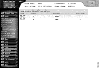
Step 3 Interpret the table as follows:
| Table Entry | Description |
|---|---|
User Num | The table entry for the user. |
User Name | The user logon name. |
Access Level | The security level for the account. See Table 2-3. |
To add a new user, follow these steps:
Step 1 Log on as a SuperUser.
Step 2 On the Navigation pane, click Node.
Step 3 Click User Profile.
The User Profile screen opens.
Step 4 On the User Profile screen, click the + icon.
The Add New User Profile form opens.

Step 5 Enter the new user parameters:
| Parameter | Description |
|---|---|
User Name | The name for the new user, expressed as a case-sensitive alphanumeric string of four to ten characters. Special characters such as @, #, and $ are allowed. |
Set Password | The account password, expressed as a case-sensitive alphanumeric string of one to ten characters. Special characters such as @, #, and $ are allowed. |
Retype Password | Password verification. |
Access level | The access privilege for the user. See Table 2-3. |
Step 6 Click Add.
The system adds the new user account.
Step 7 Repeat these steps for other users you want to authorize.
To change a user account, follow these steps:
Step 1 Log on as a SuperUser.
Step 2 On the Navigation pane, click Node.
Step 3 Click User Profile.
The User Profile screen opens.
Step 4 On the User Profile screen, click the i icon for the account you want to modify.
The Modify User Profile form opens.

Step 5 Change the user parameters:
| Parameter | Description |
|---|---|
User Name | The name for the user, expressed as a text string. |
Set Password | The account password, expressed as an alphanumeric text string of one to ten characters. Special characters such as @, #, and $ are allowed. |
Retype Password | Password verification. |
Access level | The access privilege for the user. See Table 2-3. |
Step 6 Click Modify.
The system applies the changes to the user account.
You can always change your own password, but you need SuperUser privilege to change the password of others.
To change a password, follow these steps:
Step 1 From the node menu, click Change Password.
The New Password Setting form opens.

Step 2 Enter the following parameters:
| Parameters | Description |
|---|---|
User Name | The account you want to change. |
Original Password | The old password. |
Set Password | The new password, expressed as an alphanumeric text string of one to ten characters. Special characters such as @, #, and $ are allowed. |
Retype Password | Password verification. |
Step 3 Click Modify Password. The system changes the account password.
To delete a user, follow these steps:
Step 1 Log on as a SuperUser.
Step 2 On the Navigation pane, click Node.
Step 3 Click User Profile.
The User Profile screen opens.
Step 4 On the User Profile screen, click the - icon on the row of the user you want to delete and then confirm your action.
The system removes the user from the database. Level 1 users return to their original SuperUser account.
To display a list of users who are logged in with information about them and their login session, follow these steps:
Step 1 On the Navigation pane, click Node.
Step 2 Click Login Session.
The User Session screen opens.
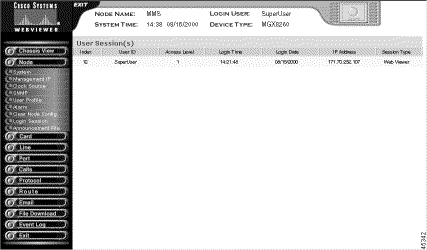
Step 3 Interpret the information as follows:
| Table Entry | Description |
|---|---|
Index | The index number of the user account. |
User ID | The login name of the new user, expressed as a case-sensitive alphanumeric string of four to ten characters. Special characters such as @, #, and $ are allowed. |
Access Level | A value associated with a user profile that determines access rights to the WebViewer |
Login Time | Time stamp in hours, minutes, and seconds of when the user logged in. |
Login Date | Month, day, and year when user logged in. |
IP Address | The address of the user's computer. |
Session Type | Type of access. |
To display duration information about announcement files, follow these steps:
Step 1 On the Navigation pane, click Node.
Step 2 Click Announcement File.
Step 3 Click Duration.
The Duration Information of Announcement Files screen opens, showing the maximum, current, and available duration of the announcement files.

To activate, deactivate, or remove an announcement file, follow these steps:
Step 1 On the Navigation pane, click Node.
Step 2 Click Announcement File.
Step 3 Click File.
The Announcement File screen opens, showing information about the announcement files.
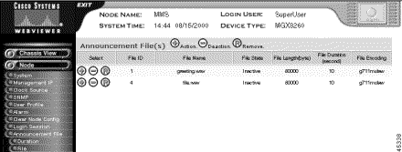
Step 4 Interpret the information about the announcement files as follows:
| Table Entry | Description |
|---|---|
File ID | The numeric identifier of the file. The system extracted this number from the file name when it was downloaded. |
File Name | The name of the file on the SCC file system |
File State | The activation state of the announcement |
File Length | The file length, in bytes |
File Duration | The file duration, in seconds |
File Encoding | The file encoding, either g711mulaw, g726encoding, or g711alaw |
Step 5 Click the +, -, or R icon on the line with the announcement file you want to activate, deactivate, or remove, respectively.
The system asks you to confirm you action.
Step 6 Click Activate, Deactivate, or Remove.
A message is displayed saying that the announcement file has been successfully activated, deactivated, or removed.
Step 7 Click Display All Announcement Files to return to the Announcement File screen.
![]()
![]()
![]()
![]()
![]()
![]()
![]()
![]()
Posted: Mon Nov 25 11:03:42 PST 2002
Copyright 1989-2000©Cisco Systems Inc.