|
|

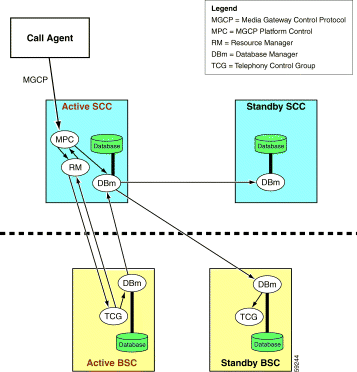
MGX 8260 media gateway supports redundant operation for all circuit cards, critical midplane bus structures and primary power feeds. (See Figure 4-1.)
System Control Cards (SCCs) and Distribution Matrix Cards (DMCs) do not require setup for redundant operation. DMCs are optional interface cards that are mated to their respective SCCs. A redundant SCC pair always occupies slots 9 and 10 of the chassis. If the system is equipped with DMCs, the DMC associated with the SCC in slot 9 is located in slot 7, the one associated with the SCC in slot 10 goes in slot 8. Either SCC can be the primary controller with the other automatically becoming the secondary.
Broadband Service Cards (BSCs) and Narrowband Service Cards (NSCs) are configured differently for failover protection. BSCs are configured in protection pairs. BSCs in different physical card slots are identically configured as a single logical card slot. Each trunk interface is physically split via Y-cables across both cards. A configuration entry made for one physical card slot is automatically mapped to the other physical card slot by the active SCC. Either BSC can be the primary with the other automatically becoming the secondary.

Cards configured for redundancy may have logical card numbers that are different from physical slot numbers. The physical slot number always represents the actual location of the card in the chassis (slots 1-16). The logical slot number is an abstract concept that helps the system keep track of primary and secondary cards.
With one-to-many (1:N) redundancy, the secondary card defaults to logical slot "0" (zero). During switchover, the secondary NSC dynamically assumes the logical slot number (and configuration database) of the primary card it protects. Figure 4-2 graphically illustrates this concept.

Logically there is only one SCC which resides in slot 9, regardless of whether the SCC on slot 9 or slot 10 is active. Typically both the SCCs will be running the same software image. However, this will not be true during image upgrades. To check whether the active and standby SCCs are running the same image, use the list card detail command (lscd) to verify the running software version.
The SCC configuration database consists of non-volatile and volatile components. Non-volatile components are stored as files in persistent memory and referenced by the reset node (restnd) command. Volatile components are stored in RAM and are cleared when the node is reset.
Non-volatile database components stored on the SCC include configuration data for:
Volatile database components stored on the SCC include:
Service card redundancy is accomplished via MGX 8260 remote procedure call (MRPC) messaging. MRPC is a proprietary version of RPC (IETF RFC-1057). All call control information originates and is communicated via the active SCC. (See Figure 4-3.) Heavy call volumes will generate corresponding amounts of MRPC messages from and to the active SCC. The SCC communicates call states stored in its databases to primary and standby BSCs via MRPC messaging. The redundant NSC does not maintain a shadow database as do the mirrored BSCs; it is updated by the SCC with the appropriate state information when it assumes control for a failed NSC.
The active SCC provides all system functionality until there is a card failure, the card is reset, or the card is removed from the MGX 8260. When any of these conditions are encountered, the standby SCC switches to active (failover) and assumes control of the system. Stable calls are not dropped when the active SCC initiates a graceful failover, however there may be a loss of voice for a fraction of a second. Call attempts will be blocked during the switchover. The newly active SCC will be available within a few seconds.
An SCC failover can also occur when:
To manually switch from the active SCC to the standby SCC, issue the switch to reset card command (resetcd <physical slot number>). For example, resetcd 9 switches from the active SCC in slot 9 to the standby SCC in slot 10. An operating SCC in the standby state must be in the adjacent slot for the switchover to occur.
Stable calls are preserved and new call attempts are blocked during the switchover process. The switchover sequence is as follows:
Both SCCs must have identical hardware configurations, including the same number and types of broadband interface modules (BIMs). Mismatched configurations will be rejected. Similarly, both SCCs must be running the same software image during normal operation.
Both SCCs share logical slot number 9 regardless of which SCC is active.
The active SCC controls the redundancy functions for all service cards via MRPC messaging. The volume of MRPC increases in direct proportion to the number of calls being processed through the MGX 8260. MRPC messaging consumes CPU time.
The DMC employs the same DS3 back card used by BSCs. A split cabling arrangement allows each trunk interface to connect to identical ports on each card. DMCs are configured as identical mated pairs. All end points and associated configuration data are completely synchronized between the active and standby DMCs. DMC redundancy is controlled from the active SCC. For additional information on trunk interconnection refer to BSC Redundancy.
If redundant SCCs are employed and the DMC option is required, two DMCs must be equipped in slots 7 and 8 of the MGX 8260 chassis. Installing only one DMC will cause a configuration mismatch between SCCs.
The major design consideration for BSC redundancy is minimal outage upon a failure of an active BSC. To accomplish this the BSCs are configured as mated pairs. All end points and associated configuration data are completely synchronized between the active and standby BSCs. BSC redundancy is controlled from the active SCC.
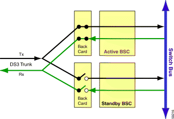
The physical cables of the DS3 trunks are split across each mated pair via Y-cables. BSC redundancy assumes all ports on a given card are one-to-one connected to its peer port via a Y-cable. DS3 back cards have a set of relays for each port. These relays are controlled by the BSC front card which places the trunk data on the MGX 8260 internal Switch Bus. On an active BSC card, these relays are closed so that signals can travel from the trunk through the front card to the Switch Bus. On the standby BSC, these relays are left open following the initialization of the card. (See Figure 4-4.)
Up to six BSCs can be equipped in a single MGX 8260 chassis; supporting a maximum of three redundant mated pairs. A BSC in slots 11 through 16 can be configured to be redundant to any other BSC in the chassis. In actual practice, assigning BSCs in adjacent physical slots is preferred due to cabling issues. The grouping of any two BSCs into a redundant pair is done via the add card redundancy command (addreds).
 |
Note Multiple primary BSCs cannot be associated with the same secondary BSC. |
Non-volatile database components stored on the SCC include configuration data for:
Volatile database components stored on the SCC and BSC include the telephony control group (TCG) which holds setup data for stable calls. (Refer to DSP Services.)
Each BSC pair shares the same logical slot number. This practice allows the SCC to continuously update the secondary BSC with identical configuration database information.
To switch an active BSC to standby, use the reset card command (resetcd <slot number>).
With mated pairs of BSCs, resetting an active card automatically transitions the standby card to active mode; the newly active card assuming call processing activities. Operating BSCs must be in both slots for the transition to occur.
For example, resetcd 11 switches the active primary BSC in slot 11 to standby, while transitioning the secondary BSC in slot 12 (mated pair—logical slot 11) to active.
|
Note Resetting a standby BSC will not cause it to transition to active. It simply reboots the card and leaves it in standby mode. |
You can also use the switch card command (swcd <slot number>) to set an active BSC to standby and a standby BSC to active. For example, swcd 11 switches the standby BSC in slot 11 to active, while transitioning the active secondary BSC in slot 12 (mated pair—logical slot 11) to standby.
For a single BSC (not mated to a secondary card), the swcd command transitions the card from one operating mode to the other—active becomes standby, standby becomes active—following a reboot.
Most importantly, the BSCs must be configured as redundant pairs prior to configuring any end point parameters on either BSC. When BSCs are configured as redundant pair via the addreds command, both BSCs—primary and secondary—are reset. All volatile connection data will be lost on both cards.
BSC redundancy is only at the card level. Port/trunk level redundancy is not supported on a BSC. A failover will not automatically occur on an active BSC experiencing faults on individual ports. Failover will only occur when a fatal error is detected for the card itself.
For NSC redundancy, one NSC is designated as the secondary card in the MGX 8260 chassis. Other NSCs are mated to the secondary card via the addreds command. Under this one-to-many (1:N) scheme, the failure of one NSC causes a transition of the secondary NSC to primary status. The redundant NSC is dynamically reconfigured by the active SCC to match the operating configuration of the failed NSC.
|
Note Only one secondary NSC is supported per MGX 8260 chassis. After the failover occurs, the other NSCs remain unprotected until the failed NSC is brought back into service. |
If one or more of the primary NSCs are equipped with back cards for connection to T1/E1 trunks, the secondary NSC must be equipped with the redundant back card (T1E1BC-RED). This back card and redundant NSC pathways in the midplane allow the secondary NSC to assume communication control of the physical interfaces on a failed primary NSC with direct connections to T1/E1 trunks.
|
Note The redundant back card is not required if the primary NSCs are operating as DSP farms for special services over BSCs and/or Fast Ethernet. |
The NSC configuration database consists of non-volatile and volatile components. Non-volatile components are stored on the SCC as files in persistent memory (flash disk) and referenced by the reset node command (restnd). Volatile components stored in RAM on the SCC and NSC are cleared when the card or node is reset.
Non-volatile database components stored on the SCC flash disk include configuration data for:
Volatile database components stored on the SCC and NSC include the TCG which holds setup data for stable calls. (Refer to DSP Services.)
By default the secondary NSC is assigned the logical slot number "0" (zero). When a failover or switchover occurs, the secondary NSC assumes the logical slot number of the failed primary NSC. (See Figure 4-5.) The logical slot number is a convenient way to identify the configuration database associated with the primary NSCs in the chassis.
When the failed primary NSC is rebooted, it remains in standby mode. Its configuration database is updated to reflect that of the secondary NSC which is now active. A manual switchover of the standby NSC is required to transition the secondary NBC to standby mode and set the previously failed NSC to active mode. When the logical slot number of the secondary NSC is restored to "0", it is available to provide redundant support to the primary NSCs.

Failover automatically switches from a primary NSC to the secondary NSC as a result of a fatal card error. Switchover manually transitions the operational modes (active/standby) of the primary and the secondary NSCs.
To switch an NSC from one mode to the other, use the reset card command (resetcd <slot number>). The logical slot number of the secondary NSC must be set to "0" indicating that it is available for switchover. If the secondary NSC is set to any other logical slot number, it is unavailable for switchover and the transition will not occur. However, the NSC will reboot regardless of the availability of the secondary NSC.
|
Note Use the list redundancy pairs command (lsreds) to identify primary NSC mapping to the secondary NSC. Use the list card status command (lscds) to display the current status of all cards in the node, including physical and logical card slot identification. |
Issuing the resetcd command to a primary NSC mapped to the secondary NSC causes both cards to transition from one mode to the other, with the newly active card assuming call processing activities. If the primary NSC becomes active once again, the secondary NSC is set to logical slot 0 making it available for redundant switching with other mapped primary NSCs.
For example, resetcd 4 will cause the active primary NSC in slot 4 to transition from active to standby. The interface relays on the primary NSC's back card will engage to route the physical interfaces across the midplane to the secondary NSC. The secondary NSC will be downloaded with the current configuration database for the primary NSC in slot 4 by the active SCC. When the download is completed, the secondary NSC will assume call processing for the primary NSC. The primary NSC will then transition to standby.
To transition the primary NSC from standby to active mode, issue the switch card command (swcd <slot number>). For example, swcd 4switches the primary NSC in slot 4 to active, while transitioning the secondary NSC in slot 6 to secondary. The primary NSC resumes call control. The logical slot number of the secondary NSC reverts to "0".
Stable calls are preserved and new call attempts are blocked during the switchover process. The switchover sequence from an active primary NSC to the standby secondary NSC is as follows:
All NSC front cards must have identical hardware configurations, including the same number and types of multiservice modules (MSMs). Mismatched configurations will be rejected. Similarly, all NSCs must be running the same software image.
If one or more NSCs is equipped with a back card for T1/E1 trunk interface, the secondary NSC must be equipped with the T1E1BC-RED redundant back card.
Each MGX 8260 chassis can only be equipped with one secondary NSC. Multiple primary NSCs should be mapped to the secondary NSC for redundancy protection using the addreds command. Up to fourteen NSCs can be equipped in an MGX 8260 chassis, thus establishing the 1:13 limit for one-to-many redundancy.
When the secondary NSC becomes active, there is no redundancy protection for other primary NSCs. Redundancy protection is restored when the logical slot number of the secondary NSC returns to "0".
The time required to transition the secondary NSC to active is longer than that required to transition between BSCs in a mated pair. This is due to the time required by the active SCC to download the configuration database of the failed primary NSC.
NSC redundancy is only at the card level. Port/trunk level redundancy is not supported on an NSC. A failover will not occur on an active primary NSC experiencing faults on individual ports. Failover will only occur when a fatal error is detected for the card itself.
Multiple bus structures are carried through the midplane:
This 1 Gbps bus spans all 16 card slots for NSC operations. It is a 32-bit data bus with five control lines running at 38 MHz.
Two identical buses—Cell Bus A and Cell Bus B—provide redundant operation. They support data transport and in-band communication with the SCCs in slot 9 and slot 10.
The switching hub for Switch Bus A is the SCC in slot 9; for Switch Bus B it is the SCC in slot 10. Slots 11 through 16 are the end points of this star bus topology.
Each point-to-point connection between an SCC and a BSC has two sets of 12 bidirectional signals, Physically, there are six independent buses concentrated onto the associated SCC.
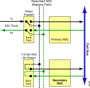
Redundant pathways have been incorporated into the MGX 8260 midplane to support the relay-driven rerouting of DS1 (T1/E1) direct interfaces from the back card of a primary NSC to the back card of the secondary NSC. (See Figure 4-6.)
The TX and RX -Tip/Ring signals from all 16 DS1s are connected directly from the I/O connectors on T1E1BC-50NR and T1E1BC-RJ48 back cards to the redundancy relays. These relays direct the DS1 signals to the primary NSC front card (after line protection circuit), or to the redundant NSC back card (T1E1BC-RED) via the redundant midplane paths. The default relay position (relays de-energized) routes the DS1 interfaces to the NSC front card. When energized the relays route all 16 DS1s to the redundant back card.
The redundant NSC back card has no relays. When the back card relays of one primary NSC are energized, the relays on all other NSCs are inhibited from being energized.
The switching hub for the TDM bus is either the active DMC in slot 7 or slot 8 paired with the associated SCC in slot 9 or slot 10. The TDM Bus is distributed to slots 1-6 and 11-16 for NSC processing.
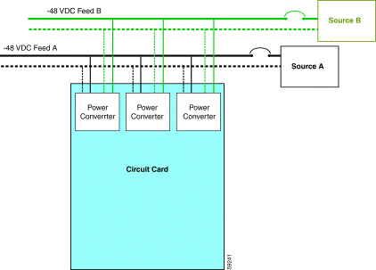
All MGX 8260 circuit cards incorporate individual power converters which accept -48VDC input and convert it to the various voltages required for individual card operation. A failure of a single card power converter has no affect on system power. A dual power bus structure supports separate -48VDC feeds to the cards. If one feed becomes disconnected, the other feed continues to support uninterrupted system operation. (See Figure 4-7.)
Ideally, the MGX 8260 chassis should be fed from two separate and independent sources for full power redundancy. Each power source should be capable of supplying the maximum required power (1800 watts) during prolonged power outages. In carrier-class deployments, this is typically accomplished via a battery/generator backed DC power plant. If an AC rectifier is used to supply -48VDC, it should be connected through an appropriately sized uninterruptible power supply (UPS).
A failover occurs when a primary (active) card fails and an automatic switchover to the secondary (standby) card occurs. A switchover is a manually initiated transition of a card from active to standby operational mode or vice versa. Both types of transitions preserve stable calls and block call attempts during the switchover process. This process is known as a graceful transition.
Cards in a standby state can be removed and replaced without disrupting the rest of the node.
 |
Caution Removing a service circuit card that is in the active state will cause the loss of all calls being processed through the card. The affect is the same as if the signal carrying cables had been cut. |
In non-redundant configurations, secondary circuit cards are unavailable. Resetting any circuit card using the reset card command (resetcd <physical slot number>) reboots the card and brings it up in its previous state. The reboot process downloads the card image from the flash disk on the SCC. The card becomes active following successful download of its configuration database. Call processing activities on the affected card are suspended until the card returns to the active state.
|
Note If the non-redundant SCC fails or is transitioned to the standby state, the entire media gateway will cease processing call attempts. You will be unable to log into the node. |
Redundant configurations include secondary cards which can assume the call processing activities of primary cards. Card state transitions cause minimal disruption of call processing activities.
To initiate a switchover from one state to the other, the CLI reset card command (resetcd <slot number>) is issued. If the primary card has been mapped to an available secondary card (addreds command), the newly active card assumes the processing of calls. The switch card command (swcd <slot number>) reverses the operating state of a card from standby to active in a mated pair.
Boot flash files reside on programmable read only memory (PROM) chips on all MGX 8260 circuit cards. Each card requires the proper boot flash files in order to successfully boot up. The CLI update flash command (updatefls <slot number>) is used to update the flash memory on an individual circuit card or matched pairs of cards.
|
Note The boot flash images on SCCs must be updated prior to those of DMCs, BSCs, NSCs. |
Software image files control the cards and execute the various command sequences once the modules have successfully booted up. The CLI upgrade command (upgd <slot number> <filename>) copies an image file to an individual circuit card or matched pairs of cards.
It is possible to upgrade the software image files without upgrading the associated boot flash files. This is because several minor releases can be expected within each major release. Boot flash files normally change only for major upgrades.
An update is a minor release usually containing codes fixes or performance enhancements. An upgrade is a major release which may contain additional features and functions. Detailed update/upgrade installation instructions are contained in the Release Notes for the specific software version.
For additional information, refer to Software Updates/Upgrades/Downgrades.
|
Caution Upgrading non-redundant cards interrupts service. Perform non-redundant upgrades during light traffic periods or during a prearranged maintenance window. |
New software images are transferred to the flash disk on the SCC using the upgd <physical slot number> command.
|
Note Physical and logical slot numbers are identical in non-redundant node configurations. |
The CLI reset node command (resetnd) reboots all circuit cards in the node. As part of the reboot process, the new images are downloaded from the SCC. All cards will be placed in active mode following a successful reboot.
|
Note This upgrade method does not interrupt call traffic. |
If required, update the flash memory of the SCCs and BSCs to be upgraded. You invoke the upgrade process by issuing the upgd <slot number> command. The image files are copied to the standby card which is then rebooted. You then have the option to commit (upgdcmit <slot number>) or cancel (upgdcancel <slot number>) the upgrade. When you commit the upgrade, the standby card initiates a switchover and copies the upgrade files to the formerly active card.
|
Note The logical slot number for the SCC is always "9". Use the lscds command to determine the logical slot numbers for all other cards in the node. |
For NSCs the upgrade process is slightly different. Before beginning this process do the following:
The following are the general steps for upgrading NSCs in redundant configurations:
Step 1 Upgrade a primary NSC using the upgd <slot number> command.
Step 2 Issue the upgdcmit <slot number> command for the primary NSC identified in Step 1.
Step 3 Issue the switch card command (swcd <slot number>) for the secondary NSC. Verify that the secondary is in standby mode (logical slot number = 0) using the list card command (lscd <slot number>).
Step 4 Repeat Step 1 through Step 3 for all primary NSCs.
|
Caution An MGX 8260 should never be powered down by simply disconnecting the power to the node. If power is cut while calls are in progress, all stable calls will be immediately terminated. |
The MGX 8260 is designed to operate 24 ours a day, seven days a week without disruption. Most service procedures, including card swaps and node resets, can be performed without turning off power to the chassis.
In the very rare circumstance when the chassis must be powered down, such as prior to moving the node to another location, follow the guidelines provided below.
Step 1 Use the call agent to discontinue the routing of calls through the MGX 8260 node. Refer to the OEM documentation supplied with the call agent for specific instructions.
Step 2 Verify that all call activity has ceased through the MGX 8260 node. Use the list active calls by resource command (lsacps). Stable calls will remain in progress until terminated by the calling or called parties.
Step 3 Issue the CLI command stopdisk 1 to shut down the flash disk on both SCCs.
Step 4 Power down the chassis by turning off the disconnect device(s) for the power feed(s). With power disconnected, the fan unit will cease moving air and all LEDs will be extinguished on the front cards.
To power up an MGX 8260 node:
Step 1 Apply power to the chassis by turning on the disconnect device (s) for the power feed(s). With power applied the fan unit should begin moving air and the LEDs on the front cards should illuminate in accordance with card boot sequences.
Step 2 Use the list cards command (lscds) to verify the operational status of all cards in the chassis.
Step 3 Log into the active SCC to verify it is ready to process calls.
Step 4 Use the call agent to reestablish the routing of calls through the MGX 8260 node. Refer to the OEM documentation supplied with the call agent for specific instructions.
![]()
![]()
![]()
![]()
![]()
![]()
![]()
![]()
Posted: Sat Sep 28 22:28:17 PDT 2002
All contents are Copyright © 1992--2002 Cisco Systems, Inc. All rights reserved.
Important Notices and Privacy Statement.