|
|

You configure Cisco MGX 8260 Media Gateway nodes from the Cisco WebViewer (see the "Cisco WebViewer Sessions" section). This chapter includes the following topics:
The Cisco MGX 8260 Media Gateway system parameters include the following:
The following table summarizes the Cisco WebViewer support for system parameter configuration.
| Configuration Task | Navigation Tree Selection | Screen | Screen Link |
|---|---|---|---|
System and group parameters, DS1 mode, or protocol mode | Node>System | System Configuration | Set |
Date and time | Node>System | System Configuration | Set |
You configure the MGX 8260 management interface for local or remote operation by setting the appropriate IP addresses and management paths. Assign management IP addresses for each of the following management interfaces that you plan to use:
 |
Note If you change the IP address of the port the WebViewer is using, you will interrupt the session. |
The following table summarizes the Cisco WebViewer support for management interface configuration.
| Configuration Task | Navigation Tree Selection | Screen | Screen Link |
|---|---|---|---|
IP addresses | Node>Management IP | Management IP Settings | Set |
IP route setup | Route>IP Route Setup | IP Route | I for details |
The MGX 8260 clock module has three synchronization options:
You assign one clock as the primary source and another as the secondary source. When using the line clock source, specify both the line and slot associated with the source.
During normal operation, the primary clock is the active source and the secondary clock is the backup. If the active source fails, the Cisco MGX 8260 Media Gateway switches to the backup clock and reports an alarm. Also, you can switch to the backup source manually. This section explains how to set primary and secondary clocks and view clock status.
The following table summarizes the Cisco WebViewer support for clock source configuration.
| Configuration Task | Navigation Tree Selection | Screen | Screen Link |
|---|---|---|---|
Primary and secondary clock source for serial lines | Node>Clock Source | Clock Source | Set |
Switching clock sources | Route>Clock Source | IP Route | Switch Clock Source |
Line and port management screens facilitate viewing, configuring, and deleting voice and data services. The following list summarizes the line configuration parameters:
|
Note The DS1 and E1 modes are mutually exclusive. |
The DMC maps source DS1 channels from the DS3 interface to destination DS1 channels on the NSCs. The mapping is one-to-one and can connect any source DS1 to any destination DS1.
|
Note The NSC should be in the backplane more for correct DMC operation. |
| Task | Navigation Tree Selection | Screen | Screen Link |
|---|---|---|---|
View all lines | Line>All-Lines>All-Lines | Common Line | i for details |
DS0 channel configuration | Line>Dsx0>All-Dsx0 | Dsx0 Status | - to delete |
DS1 line configuration | Line>Dsx1-T1>All-Lines | Dsx1-T1 Line Configuration | + to add |
E1 line configuration | Line>E1>All-Lines | E1 Line Configuration | + to add |
DS3 line configuration | Line>Dsx3>All-Lines | Dsx3 Line Configuration | + to add |
DMC line mapping | Line>DMC T3-T1 Mapping | DMC T3-T1 Mapping | + to map |
Fast Ethernet line configuration | Line>Ether>All-Lines | Ether Line Configuration | + to add |
Fast Ethernet admin status change | Line>Ether>All-Lines | Ether Line Configuration | Link Up or Link Down |
OC-3 line configuration | Line>SONET>All-Lines | Sonet Line Configuration | + to add |
SONET E-RDI and trace configuration | Line>SONET>All-Lines | Sonet Line Configuration | i to change |
This section describes the procedure for viewing, adding, or changing voice ports. Voice ports identify the physical location and characteristics of a voice interface at a DS0 level. A Media Gateway Controller manages SVC (Switched Virtual Circuit) end points and connections.
The Cisco MGX 8260 Media Gateway identifies a voice port by a logical port number that is independent of the port's physical location. The following parameters describe the physical location:
NSC lines always need a voice port configured; BSC lines have a default configuration. When you add or change a voice port, you associate a logical port number with these physical descriptors. Voice ports have settings for dejitter, packet loading, and other voice parameters.
| Task | Navigation Tree Selection | Screen | Screen Link |
|---|---|---|---|
View all ports | Port>All-Ports | Common Port | i for details |
View voice ports | Port>Voice>All-Ports | Voice Port Configuration | + to add |
Active call information is useful for audits or trouble analysis. The Cisco MGX 8260 Media Gateway displays active calls as follows
The following table summarizes the Cisco WebViewer support for active calls:
| Task | Navigation Tree Selection | Screen | Screen Link |
|---|---|---|---|
View calls by resource | Calls>Physical Calls>All-Calls | Active Call Physical Table | None |
View calls by transaction | Calls>All-Calls>All-Calls | Active Call Physical Table | None |
This section describes how to configure and view MGCP (Media Gateway Control Protocol). The following diagram shows how to configure MGCP IP addresses in a fullyredundant system (see Figure 7-1).
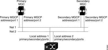
A non-redundant system consists of a primary MGC network, the Cisco MGX 8260 Media Gateway, and an IP network. You can add the secondary network or MGC for more reliable operation.
To configure MGCP, you perform the following tasks:
The following table summarizes the Cisco WebViewer support for MGCP:
| Task | Navigation Tree Selection | Screen | Screen Link |
|---|---|---|---|
Switch from IPDC to MGCP | Node>System | System Configuration | Set |
View connection status | Protocol>MGCP>Default | MGCP Default Setting |
|
Domain name configuration | Protocol>MGCP>Default | MGCP Default Setting | Set |
IP address configuration for primary MGC, secondary MGC, and local port | Protocol>MGCP>Default | MGCP Default Setting | Set |
Core MGCP parameter configuration | Protocol>MGCP>Core | MGCP Core Setting | Set |
View message statistics | Protocol>MGCP>Message Stats | MGCP Message Statistics |
|
Default call setup parameters | Protocol>MGCP>MPC Scalars | MPC Scalar | Set |
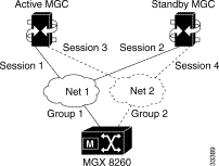
The session manager organizes individual sessions into groups and sets (see Figure 7-2).

The backhaul sessions and groups include the following components:
When adding sessions, you create a structure that supports reliable operation. The goal for a fully redundant system is to provide multiple management sessions to multiple MGCs via multiple physical networks (see Figure 7-3).
If the MGC cannot handle all D Channels in one session set, then configure another similar set using different UDP ports and D Channels.
To configure ISDN backhaul signaling, set the following parameters:
The following table summarizes the Cisco WebViewer support for sessions:
| Task | Navigation Tree Selection | Screen | Screen Link |
|---|---|---|---|
Session set configuration | Protocol>Backhaul>Set | Session Set | + to add |
Session group configuration | Protocol>Backhaul>Group | Session Group | + to add |
Session configuration | Protocol>Backhaul>Session | Session | + to add |
The Cisco MGX 8260 Media Gateway extends D Channel signaling to an MGC via a backhaul channel (see Figure 7-4).

Each BSC contains 168 T1 lines, each a potential Primary Rate ISDN line. An ISDN line contains 24 channels, one of which is the D Channel that carries the signaling information for the other 23 channels. The BSC card can terminate a D Channel signaling stack and pass the payload to an MGC, via the SCC, using a backhaul session.
The following procedures describe how to configure a D Channel for a backhaul session. The procedures assume you already have a DS3 line, and have provisioned a PRI ISDN line on one of its circuits. ISDN D Channels can be difficult to configure because they have many settings, so the Cisco MGX 8260 Media Gateway simplifies the process by grouping common settings into two types of profiles:
When adding D Channels, you simply specify suitable profiles that contain the desired configuration set. You can create profiles using default settings that accommodate the signaling requirements for common applications.
The Cisco MGX 8260 Media Gateway simplifies the process of creating D Channels with DLSAP and MACSAP profiles. These profiles provide a template of parameter settings that you apply when adding D Channels. Changes you make to the profiles apply only to lines you subsequently add, not to lines that already exist. If you want to change the configuration of a D Channel, delete it first and then recreate a new one using the new template.
The following section describes the high-level procedure for configuring a D Channel on an existing DS3 trunk:
Step 2 Define a MACSAP profile.
Step 3 Define a D Channel on a PRI ISDN line within the DS3 trunk, using the profiles you defined in Steps 1 and 2.
The following table summarizes the Cisco WebViewer support for D Channels:
| Task | Navigation Tree Selection | Screen | Screen Link |
|---|---|---|---|
MACSAP profile configuration | Protocol>ISDN>Macsap Profile | Macsap Profile | + to add |
D Channel configuration | Protocol>DChan Config | D Chan Config | + to add |
Viewing LAPD parameters | Protocol>ISDN>Lapd | LAPD Card Table | none |
IPDC is an alternative to the MGCP protocol for controlling voice calls through the Cisco MGX 8260 Media Gateway. When using IPDC, you do not have to configure sessions or backhaul channels.
|
Note Cisco MGM does not support IPDC. |
To configure IPDC, configure the following parameters:
The following table summarizes the Cisco WebViewer support for IPDC:
| Task | Navigation Tree Selection | Screen | Screen Link |
|---|---|---|---|
Switch from MGCP to IPDC | Node>System | System Configuration | Set |
View IPDC status | Protocol>IPDC>Configuration | IPDC Configuration |
|
IP address configuration | Protocol>IPDC>Configuration | IPDC Configuration, Soft Switch Configuration pane | Set |
Pseudo IP address configuration for Fast Ethernet ports | Protocol>IPDC>Configuration | IPDC Configuration, Status and Core Setting pane | Set |
IPDC core protocol settings | Protocol>IPDC>Configuration | IPDC Configuration, Status and Core Setting pane | Set |
COT configuration | Protocol>IPDC>Configuration | IPDC Configuration, COT Configuration pane | Set |
IPDC timer configuration | Protocol>IPDC>Timer | IPDC Timer Configuration | Set |
IPDC and health check activation | Protocol>IPDC>Configuration | IPDC Configuration, Soft Switch Configuration pane | Set |
Announcement files contain voice messages that the system can play for users. The announcement file parameters include the following:
The following table summarizes the Cisco WebViewer support for announcement file configuration.
| Configuration Task | Navigation Tree Selection | Screen | Screen Link |
|---|---|---|---|
View duration information | Node>Announcement File>Duration | Duration Information for Announcement Files |
|
Activate, deactivate, or remove a file | Node>Announcement File>File | Announcement File | + to activate |
![]()
![]()
![]()
![]()
![]()
![]()
![]()
![]()
Posted: Thu Jul 18 00:25:39 PDT 2002
All contents are Copyright © 1992--2002 Cisco Systems, Inc. All rights reserved.
Important Notices and Privacy Statement.