|
|

This chapter describes how to install the hardware components that make up an MGX 8250 switch.
 |
Note Most of the information in this chapter applies to an open rack installation. For a Cisco rack, you need only the instructions that apply to electrical connections. Information about the Cisco rack itself appears in "Site Preparation." |
Although the viewpoint of this chapter is that a plan exists for the network and the location of each card, it reviews some of the planning decisions for the switch. For a list of physical and electrical characteristics of the switch, see "System Specifications."
The MGX 8250 switch ships in one of two arrangements:
Note the following information before installing anything:
 |
Note The low-profile configuration cannot be upgraded using later versions of the MGX 8250 boards. |

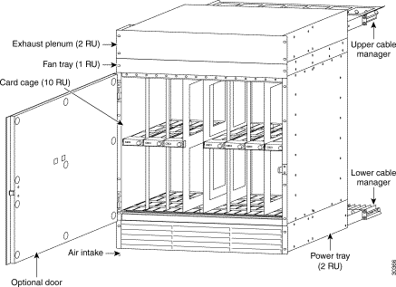
The minimum distance between left and right mounting rails as you face the rack is 17.75 inches or 45.08 cm. (The width of the enclosure modules such as card cage, fan tray, and so on, is 17.73 inches.) If a standard 19-inch (48.25 cm) rack cannot provide this space, a 23-inch rack is necessary. Each module has flanges that serve as the front mounting brackets in a 19-inch rack. For a 23-inch rack, Cisco Systems provides special brackets. The 19-inch rack version appears in Figure 4-1.
You can attach the enclosure modules to the mounting rails at the front, using the front flanges on each module. The flanges are visible in Figure 4-1.
The mounting rail locations comply with sites that require mounting on front, middle, and rear mounting rails, as Figure 4-2 shows.

This section describes how to install the mandatory and optional modules that make up the enclosure of the MGX 8250 switch. For open rack installations, Cisco advises you to remove the cards and optional AC power supplies before installing the switch. Therefore, this section begins with the steps for removing and installing these items.
When you install the modules, keep in mind the following:
1. Due to the presence of a disk drive on each Processor Switching Module (PXM), you should leave the PXMs in place. If you remove a PXM, handle it with caution to preserve disk alignment.
2. For an AC-powered, mid-mount rack installation, you must remove the AC power supplies.
3. The weight and bulk of even an empty card cage mandate that two or more people install it, otherwise one person with a mechanical lift can install the switch.
4. As you place each module in the rack, be sure that it does not drag across the surface of the module beneath it. Therefore, as you move it into position toward the back of the rack, lower the module to rest only when it is all the way in the rack and directly above the module beneath it.
5. The vertical spacing between all modules must be in the range .047"-.077" (about 1/16") or
0.119 cm-0.196 cm. By leaving this space, you can easily remove a single module if necessary. This clearance is not necessary beneath the exhaust plenum.
6. Two installers can maneuver a module to provide the vertical gap while driving in the first two screws. If you alone are installing the modules, use a non-abrasive object to create this gap until you have installed the screws. For the modules that have four or eight screws, two people are required only until the bottom two screws are in place.
7. If an enclosure module takes more than two screws, install the two bottom screws first.
8. If space around a mid-mount installation is too narrow, you can use thread-forming screws to pre-thread mounting holes. The pre-threaded holes make screw insertion much easier.
 |
Caution If you use a power-screwdriver, do not use it on captive screws. |
 |
Caution When moving a Cisco-supplied cabinet, do not push the cabinet at its sides. Instead, grip its front or back edges. |
 |
Caution Make sure that mounting the equipment does not create a hazardous condition due to uneven mechanical loading. The rack should be securely supported. |
 |
Caution The location of the rack must allow air to flow unrestricted in and out of the switch. |
 |
Warning Before handling any cards, ground yourself to the card cage with a wrist strap. |
The information in the section applies to only an open rack installation. It identifies the installation sequence for the switch in general. For the sequence of enclosure modules in particular, see "Stacking Order for Enclosure Modules."
The installation sequence is:
Step 1 Remove all cards (except the PXMs) and the power supplies according to the instructions in "Removing a Front Card," "Removing a Back Card," and "Removing a 220 VAC Power Supply."
Step 2 Install enclosure modules in the order listed in 'Stacking Order for Enclosure Modules" and according to the instructions in "Installing the Enclosure."
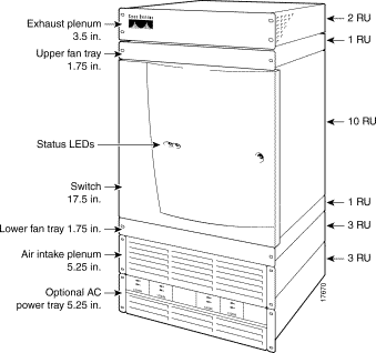
A specific stacking order is mandatory. The following stacking order list begins with optional brackets then continues with the bottom module through the module at the top of the enclosure. Each of these modules has its own section with detailed installation steps. See Figure 4-3 for the location of each module.
1. Optional spacers for 23-rack installation
2. Optional AC power assembly
3. Air intake chamber
4. Lower spacer unit or optional lower fan tray
5. Card cage
6. Upper (mandatory) cooling unit fan tray
7. Exhaust plenum
Each single-height front card has a latch to secure it when the card connects to the backplane. Each double-height card has a latch at the top and the bottom. (See Figure 4-4.)

Step 1 Press the tip of a small, flat-blade screwdriver into the slot of the insertion/extractor lever until the latch springs open by approximately 10 degrees. For double-height cards, repeat this action at the bottom latch.
Step 2 To dislodge the card from the connector, lift the lever.
Step 3 Gently pull the card out of the card cage.
To remove a back card:
Step 1 Use a flat-blade screwdriver to loosen the two retaining screws in the faceplate.
Step 2 Simultaneously pull out both extractor levers to pull the card from the backplane connector after you loosen the screws.
Step 3 Gently pull the card out of the card cage and store it in a safe location.
Removing 220 VAC power supplies makes the AC power tray installation much easier. For a mid-mount installation, however, you must remove the power supplies for reasons explained in the forthcoming section "Installing the Enclosure." Before executing the following steps, make sure you have a record of the location of each power supply.
Step 1 Remove the air intake grille by inserting a flat-blade screwdriver in the access hole at the top then rotating the screw until the spring latch opens. See "Release" in Figure 4-5.
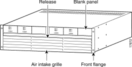
Step 2 Tilt the air inlet grille down to about a 45-degree angle, then lift it out and set it aside. This action exposes the hinged door that serves as the power supply retainer bracket.
Step 3 With a flat-blade screwdriver, unscrew the captive retainer screw in the center of the hinged door and tilt the door down.
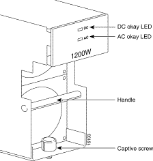
Step 4 Loosen the captive screw at the front-bottom of the power supply you want to remove. (See Figure 4-6.)
Step 5 Grip the handle, then remove the supply.
Using the guidelines in "Introductory Information," install each component according to the steps in this section. The section contains descriptions for the enclosure modules and includes descriptions for the power cables and cable manager.
Step 1 If this switch requires the brackets for a 23-inch rack, attach them to the enclosure modules.
Step 2 For an AC-powered system, install the optional AC power tray. Its height is three rack-mount units (three RUs are 5.25 inches or 13.34 cm). See Figure 4-7.
For a mid-mount installation, insert each mounting screw from the inside the power tray so that the nut is on the outside of the tray. This approach is necessary to allow room for power supplies in either the first or last power supply trough.

While you secure the front of the power supply tray with the front screws, hold the adjacent front flange of the tray slightly to the outside so the hinged door can freely open and close. See "Front Flange" in Figure 4-5. The space between the right-angle edge of the flange and the edge of the hinged door should be about the thickness of a thumbnail.
Step 3 For a DC-powered system, install the DC-PEMs at the back of the air intake module. If you install only one DC-PEM, install it on the right. (See Figure 4-8 and Figure 4-9.)

Step 4 Install the air intake module (3 RUs). (See Figure 4-10.)

Step 5 Install the optional booster fan tray if present, otherwise install the spacer unit (1 RU). See Figure 4-11. If you install a fan tray, note the label that says "This Side Up."
Step 6 Install the card cage (10 RUs). When you move the card cage into position, be sure the base of the card cage at the back fully clears the top-rear edge of the spacer unit or fan tray beneath it.
Step 7 Install the mandatory fan tray (1 RU). See Figure 4-11, and note the label that says "This Side Up." When you move the fan tray into position, make sure its base at the back fully clears the top-rear edge of the card cage beneath it.

Step 8 Install the exhaust plenum (2 RUs).
If you install the cable manager, proceed to the next section, titled "Installing the Cable Manager," before you do the tasks in the section titled "Installing the Fan Power Cabling."
Step 1 Holding the bracket with one hand, position it so the lower flange fits inside the card cage wall. Make sure the screw hole on the bracket aligns with the screw hole on the card cage.
Step 2 Drive in the screw.
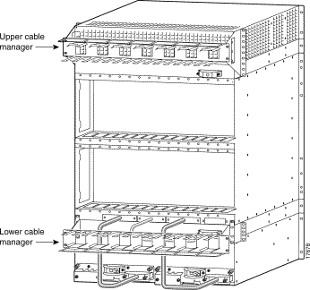
Next, use the provided 10-32 sized screws to install the cable managers. As Figure 4-12 shows, the orientation of the cable managers must be such that the cable channels on the top cable manager are on top, and the cable channels on the bottom cable manager are on the bottom.
 |
Note Fiber optic cabling and copper cabling take different paths on the cable manager. Use the cable channels for the copper cabling, but run the fiber optic cables over the sheet metal portion. |
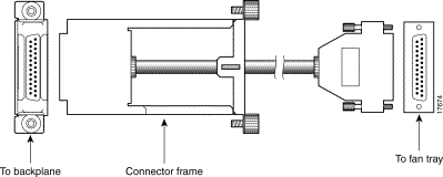
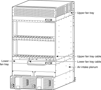
The fans receive power off the backplane by way of a fan power cable. To reach the backplane connector, the fan power cable D-connector passes through an outer hole at the base of the card cage. At the fan-tray end of the cable, the D-connector plugs into J1—the only connector at the back of the fan power tray. See Figure 4-13 for an illustration of the fan power cable and Figure 4-14 and Figure 4-15 for illustrations of the card cage area with the cabling holes for AC and DC-powered systems. Note that the holes for system power cabling alternate with the smaller holes for fan power. From left to right, the sequence of access holes is:
1. System power.
2. Fan power.
3. System power.
4. Fan power. Use the fan power access hole on the far right for the upper fan tray.
To install the fan power cabling:
Step 1 With the narrow row of pins shown in Figure 4-13 in the D-connector on the bottom, use two hands to slip the framed connector through the access hole at the base of the card cage. Move the connector straight toward the backplane so you can guide it through the second internal guide.
With the D-connector fully inserted in the backplane connector, the captive screws on the frame are clearly aligned with the threaded holes on the chassis.
Step 2 Tighten the captive screws only enough to secure the connector. Do not apply much torque, and do not use a power screwdriver.
Step 3 Insert the D-connector in J1 on the fan tray and tighten the captive screws only enough to secure the connector. Do not use a power screwdriver.
Step 4 For the mandatory fan tray, position its power cable to run through the channel formed by the mounting bracket on the right.
A system power cable carries current from either a DC PEM or AC-DC power module to the backplane. The cable is the same for either type of power system. (See Figure 4-16.)
The end with the metal frame around the D-connector plugs into the larger of the access holes to the backplane. The other end connects to the power supply and has a protective connector cover, shown in Figure 4-16, which prevents the possibility of shorting the DC power supply while the connector is removed. You will need to press the connector cover on the cable side to lift the cover away from the D-connector when installing the cable into the PEM.
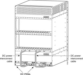
From left to right, the first and third access holes are for system power. See Figure 4-17 for an AC-powered system and Figure 4-18 for a DC-powered system.


Both AC and DC-power assemblies have D-connectors to receive the unframed connector. Connecting a power cable at the backplane has no requirement to connect at a particular connector.
To install system power cabling:
Step 1 With the narrow row of pins in the D-connector on the bottom, use two hands to slip the larger connector through the access hole at the base of the card cage.
Step 2 Move the connector straight toward the backplane so you can guide it through the second, internal guide.
When you have fully seated the D-connector in the backplane connector, the captive screws on the frame are clearly aligned with the threaded holes on the chassis.
Step 3 Tighten the captive screws only enough to secure the connector. Do not apply much torque. Do not use a power screwdriver.
Step 4 Insert the D-connector without the frame in J1 on the power assembly
Step 5 Tighten captive screws only enough to secure the connector. Do not use a power tool.
If you need to swap a DC PEM in a redundant system with the power on, see "Swapping a Primary or Redundant DC PEM With Power On" for instructions.
If necessary, you can replace either a primary or a redundant PEM with power on. To avoid possibly tripping the system circuit breaker in the process, use the sequence described in this section for disconnecting and reconnecting the system power cabling.
To remove a PEM with system power on:
Step 1 Turn off the circuit breaker on only the PEM you intend to replace.
Step 2 Turn off the branch circuit at the DC source (the distribution box, for example) for the correct branch.
Step 3 Disconnect the three DC source wires at the wiring block on the PEM.
 |
Note The following Caution and Steps 4 through 6 only apply to earlier builds without the plastic protector cover on the cable connector plugged into the PEM. If you are using a cable connector with the plastic protector cover, proceed to Step 7. |
 |
Caution The cable connector must be disconnected at the backplane end during hot PEM insertion or removal. If you disconnect the cable first at the PEM, the system power cable is still hot. These hot contacts may inadvertently touch a surface of the chassis or metal connected to the chassis. If this contact occurs, the -48 VDC is shorted to the chassis, and the circuit breaker on the still-active PEM open shutting down the system. |
Step 4 Locate the backplane end of the system power cable for the PEM you intend to replace.
Step 5 At the backplane end of the system power cable, loosen the captive screws on the cable bracket.
Step 6 Pull the cable bracket out approximately one inch to disconnect the cable.
Step 7 At the end of the system power cable connected to the applicable PEM, loosen the jack screws and disconnect the cable from the PEM.
Step 8 Remove the PEM.
To install a PEM in a system with power on:
Step 1 Make sure the circuit breaker is in the off position.
Step 2 Insert the PEM and tighten the captive mounting screws.
Step 3 Connect the system power cable first at the PEM.
 |
Note Step 4 only applies if you disconnected the backplane connector in Step 4 of the previous procedure; otherwise, proceed to Step 5. |
Step 4 Connect the backplane end of the system power cable to the backplane. This requires some dexterity, especially if the cabling around the system power cable is dense. Grasp the cable bracket at the captive screws and gently push the bracket straight in. Furthermore:
Step 5 Tighten the connector screws.
Step 6 Attach the three DC source wires at the wiring block on the PEM.
Step 7 Turn on the DC power at the circuit branch source.
Step 8 Turn on the circuit breaker of the PEM.
If you left the AC power supplies in the tray during installation, proceed to the next section, "Connecting 220 VAC Power to the Switch." To re-install power supplies you have removed:
Step 1 Push each power supply into the tray. When it almost reaches the end of the slot in the tray, a slight resistance is encountered. Push the power supply slightly farther in to achieve the final position and full connector mating.
Step 2 Secure each supply to the tray by tightening the captive screw at the bottom-front of each supply. For slots without a power supply, the hinged door on the tray should have a removable, blank panel.
Step 3 Close the hinged door and secure it with the screw at the top-center of the door.
If you removed the AC power supplies before installing the AC power tray, re-install them in the same locations they had when the switch arrived. If necessary, use the steps in the section titled "Installing 220 VAC Power Supplies." At the switch, the AC power receptacle is an IEC-type with a clamp.
 |
Note The AC voltage range is 200-240 VAC. |
To install the power cord:
Step 1 Loosen the cable clamp around the receptacle, otherwise the plug may not properly fit.
Step 2 Firmly seat the plug. This may require you to hold the chassis with one hand while you push the plug in with the other hand.
Step 3 Tighten the clamp.
Cisco can provide AC power cords with the following types of AC wall plugs:
If you left the 110 VAC power supplies in the tray during installation, proceed to the next section, "use the following procedure to re-install power supplies you have removed:
Step 1 Loosen the captive screw at the top of the AC Power Supply Module that secures it to the AC Power Supply Tray.
Step 2 Insert the AC Power Supply Module.
Step 3 Tighten the captive screw at the top of the AC Power Supply Module.
Step 4 Attach the DC power cable.
Step 5 Attach the AC power input cable.
Step 6 Turn the AC source power on.
Step 7 Turn the Enable switch on the AC Power Module to On.
Step 8 From the front of the MGX 8250, verify that both LEDs (AC and DC) on the replacement AC Power Supply Module are lit.
This section describes how to connect the DC wiring to the switch. This switch uses 6 AWG
(10 square mm) copper wire. For details on wire lengths, wire gauges, and grounding concerns, see "Site Preparation."
Each primary or redundant DC source connects to one or two DC PEMs in the switch. Make sure that each source comes from a dedicated branch circuit. Only a source that complies with safety extra low voltage (SELV) requirements in AS/NZ 3260 and EN60950 should connect to a DC-powered switch. The wiring for a DC-powered system is provided by the customer and must be three-wire solid or stranded copper. Its insulation should be rated for 60 degrees centigrade.
The recommended terminal lug to be used with the DC PEM terminal block is Panduit LCAS6-10-L.
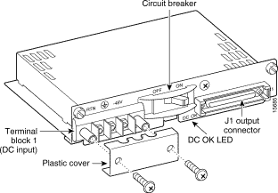
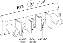
For installations where protection conduit is not required by local codes, the plastic cover visible at the bottom of Figure 4-19 is sufficient. Two phillips screws secure this cover to the PEM.
Use the visual information in Figure 4-19 and Figure 4-20 to connect the DC wiring.
Step 1 Cut the appropriate wire lengths.
Step 2 Strip the insulation back 0.25 inches (6 mm).
Step 3 With power off at both the switch and the source, attach each wire to the #10-32 lugs. See Figure 4-20.

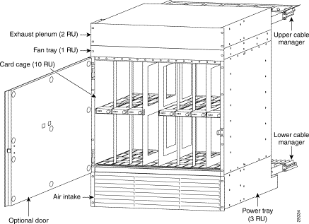
The version of the MGX 8250 powered by either a single or redundant 110 VAC power supply is shown in Figure 4-21. The version shown has the optional door installed.
The power supply will accept voltages in the ranges of 100 VAC to 130 VAC.
The 110V power supply has a maximum output power of 1200W per power supply module. However, because of safety limitations imposed on the line cord, the power is restricted to 1000 Watts output.
The system is limited to using cards from release 1.4 and earlier. Cards in future releases are not supported by this system.
 |
Note The low-profile 110 VAC version of the MGX 8250 has a combination air intake plenum and power supply tray. |
Since the card cage for the MGX 8250 low-profile AC version is identical to the standard MGX 8250 card cage, follow the procedures in the "Installing the Cards" section for removing and installing cards.
The 110 VAC power supplies are accessed from the rear of the unit as described in the following procedure. The front grill is not removable on this switch.
Step 1 Turn off the power switch on the power supply.
Step 2 Disconnect the AC input power cable from the power supply.
Step 3 Remove the DC power cable, shown in Figure 4-22 , from the power supply side, leaving the other side attached to the motherboard.
Step 4 Using a phillips screwdriver, remove the screw at the rear of the unit as shown in Figure 4-22
Step 5 Gently pull the power supply from the case toward the rear.
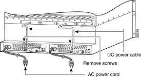
To replace a 110 VAC power supply refer to Figure 4-22 and use the following procedure:
Step 1 Slide the power supply into a vacant position and secure with the screw, shown in Figure 4-22, using a Phillips screwdriver.
Step 2 Connect the DC power cable to the power supply. Make certain the connectors are firmly seated.
Step 3 Secure the cable connector with the two connector screws using a phillips screwdriver.
Step 4 Connect the AC power cable to the power supply.
Step 5 Turn the power switch on the power supply to its on position.
This completes the removal and installation of the 110 VAC power supply.
After the system has been mounted, connect the fan power cable to the mother board and to the fan power connector on the fan tray as shown in Figure 4-23. Route the power cable as shown in Figure 4-23.
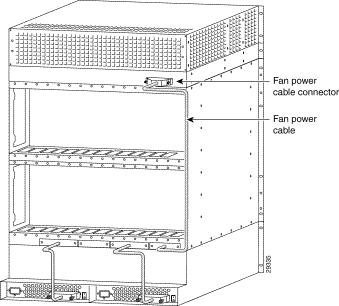
The MGX 8250 low-profile, DC version is shown in Figure 4-24. Figure 4-25 shows the rear of the unit, the connections between the system motherboard and the PEMs, and the routing for the fan power cable. With the proper rack, up to 3 of these units can be placed in a standard 7-foot rack. The low-profile system is 15 RU high.
The MGX 8250 low-profile system has thermal limitations that limit the type and number of cards that can be installed in the system to a maximum total power dissipation of 1000 Watts. The thermal limitations are due to having only a single fan tray available. See Table A-2 "Physical Characteristics and Power Consumption by Card" for detailed thermal information on the card content of a system. System software recognizes the system card and fan tray configuration and will issue an error message if the thermal limitations are exceeded.
The MGX 8250 low-profile system supports cards of Release 1.4 and earlier but will not support cards for future releases.
Adding and removing cards in the card cage for the low-profile DC version of the MGX 8250 is identical to the procedure described in the "Installing the Cards" section. Follow this procedure for installing and removing cards.

Connect the fan power cable as shown in following the instructions in the "Installing the Fan Power Cabling" section.
In the same manner, install the DC power cables to the motherboard and PEM following the instructions in the "Connecting DC Power to the Switch" section.
This section describes how to install front and back cards. Service modules can go in any slot except reserved slots 7, 8, 15, 16, 23, 24, 31, and 32. The PXMs and optional SRM core cards occupy these reserved slots. Additionally, upper slots 9 and 10 and lower slots 25 and 26 do not have a special bus for the bulk distribution feature. For this reason, Cisco recommends that if the switch contains one or more Route Processor Modules (RPM/Bs), the first 2 RPM/Bs go in slots 9 and 10.
 |
Caution To prevent damage to the cards from static electricity, put on a wrist strap and connect it to any convenient metal contact on the switch before you touch any cards. |
 |
Caution Handle the PXM front card very carefully to preserve the alignment of the attached disk drive. Do not drop or bump the PXM. |
 |
Caution Inserting the cards in the correct slot is important for all cards but especially for the back cards because of the potential for electrical damage. If you insert a service module back card into a PXM back card slot (7, 8, 23, or 24), damage to the card and backplane may result. If you accidentally insert a back card for a service module into slot 7, 8, 23, or 24 then observe incorrect switch operation, check for bent or damaged pins on the backplane and the back card. |
Verify the accuracy of the intended slot for each card before you begin installing the cards.
To install a front card:
Step 1 Position the rear card guides over the appropriate slot at the top and bottom of the cage.
Step 2 Gently slide the card all the way into the slot.
Step 3 Press the insertion-extractor lever until it snaps into the vertical position.
 |
Note The card should slide in and out with only slight friction on the adjacent board's EMI gaskets. Do not use force, and investigate any binding. |
Verify the accuracy of the intended slot for each card before you begin installing the cards:
 |
Caution Before using the switch, verify that the daughter card type on the PXM corresponds to the uplink card type. Serious damage may result if the power is on and these cards are mismatched. |
To install a back card:
Step 1 Make sure the two extractor levers are in the "in" position. As you move the card, the levers should be flush with the vertical edge of the back card.
Step 2 Gently slide the card all the way into the slot.
Step 3 Push the card into the connector.
Step 4 Tighten the two captive screws on the card faceplate only enough to secure the card.
Service modules can have either 1:1 redundancy or 1:N redundancy. For information on installation requirements, refer to the section titled "Service Resource Module" in this chapter. For configuration steps, see the section for the SRM in "Card and Service Configuration." For instructions on how to use the CiscoView application to configure redundancy, refer to the CiscoView user-documentation.
For hot standby, place the card sets in the same shelf and connect the appropriate Y-cable to the paired ports on the active and hot-standby cards. The hot-standby card will automatically configure itself to match the configuration of the primary card. This process may take up to eight minutes. After the configuration transfer process is completed, the transfer from the primary to the hot-standby card takes less that one second regardless of the number of connections. Any subsequent changes to the primary card are automatically transferred to the hot-standby card configuration so the two cards maintain the same configuration. Refer to the "Redundancy for Frame Service Modules" section for instructions for setting up a redundant pair. Applicable service modules are:
To determine the hot standby status of the system, use the command dsphotstandby.
For 1:N redundancy, an MGX Service Resource Module-3T3 (MGX-SRM-3T3/B) card set is necessary. It supports 1:N redundancy for the following:
With 1:N redundancy, a group of service modules has one standby module. Redundancy by way of the redundancy bus on the MGX-SRM-3T3/B requires the redundant card group to have one of the following special back cards for redundancy support:
This section describes the unique requirements for installing the Processor Switching Module (PXM) card set and briefly describes the features of each associated back card. The PXM card set consists of the PXM front card, the PXM User Interface back card (PXM-UI), and various uplink back cards that can serve as either a trunk or a UNI. Each description includes a faceplate description and a list of applicable cables. For instructions on how to configure the PXM functionality for switch and network control, see "Configuring the MGX 8250 Switch." For lists of the physical details of PXM cards, standards compliances, and so on, see "System Specifications."
 |
Note The common instructions for installing any card in this switch appear in an earlier section, "Installing the Cards." |
 |
Caution Handle the PXM front card very carefully to preserve the alignment of the attached disk drive. Do not drop or bump the PXM. |
 |
Caution Before using the switch, verify that the daughter card on the PXM corresponds to the uplink card type. Serious damage may result if the power is on and these cards are mismatched. |
 |
Note If you accidentally insert a back card for a service module into slot 7, 8, 23, or 24 then observe incorrect switch operation, check for bent or damaged pins on the backplane and the back card. |
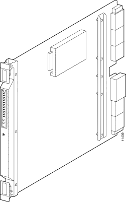
Primarily, the PXM1, shown in Figure 4-26, controls the switch and provides 1.2 Gbps of non-blocking, shared memory switching. In addition, the PXM features are:
For descriptions of switch configuration tasks, see "Configuring the MGX 8250 Switch." For descriptions of how to modify partitioning, specify APS, and add UNI-port connections, see "Card and Service Configuration."
The PXM User Interface card (PXM-UI) connects the switch to the various ports which allow you to communicate with and control the switch. Install the PXM-UI in the upper half of the back of the PXM. See Figure 4-27 for the connectors on the PXM-UI. For specifications on this card, see "System Specifications."
The back card also provides:
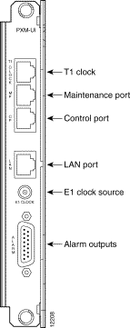
If external equipment or a local digital central office is to provide synchronization to the MGX 8250 switch, you can connect the external clock source to the PXM-UI back card. For a T1 clock input, connect the source to the RJ-45 connector labeled "T1 Clock." For an E1 clock input, use the SMC connector marked "E1 Clock." See "Configuring the MGX 8250 Switch," for this switch-level feature.
Dry contact relay closures are available for forwarding MGX 8250 alarms to an alarm system. Separate visual and audible alarm outputs are available for major and minor alarm outputs. The MGX 8250 alarm outputs are available on a DB-15 connector on the PXM-UI back card faceplate. Refer to "Cabling Summary," for the pinouts on this connector. Use switchboard cable for running these connections.
An illustration of the long-reach OC-12 card appears in Figure 4-28. For specifications on this card, refer to "System Specifications." Note that Automatic Protection Switching (APS) requires the "B" model—an SMFLR-1-622/B.

The intermediate reach OC-12 back card appears in Figure 4-29. For specifications on this card, refer to "System Specifications." Note that Automatic Protection Switching (APS) requires the "B" model—an SMFIR-1-622/B.

The SMF-155 back card provides a physical single-mode fiber optic SONET OC-3 interface that conforms to ANSI T1.105 and GR-253-CORE standards. This interface uses SC connectors, and redundant configurations are supported through Y-cables. See Figure 4-30 for an illustration of the OC-3 back card. For specifications on this card, refer to "System Specifications." Note that Automatic Protection Switching (APS) requires the "B" model—an SMF-155/B.

An illustration of the two-port T3 back card appears in Figure 4-31. For card specifications, refer to "System Specifications."

Two versions of the BNC-2E3 card are available. The BNC-2E3A applies to Australia only, and the BNC-2E3 applies to all other sites that require E3 lines on the PXM uplink card. An illustration of the two-port E3 back card appears in Figure 4-32. For specifications on this card, refer to "System Specifications."

The MGX-AUSM-8T1/B and MGX-AUSM-8E1/B (or simply "AUSM/B" as a generic reference to both card sets) are multipurpose front cards that use an 8-port T1 or E1 back card. The AUSM/B supports the following applications:
1. ATM Inverse Multiplexing N x T1 and N x E1 trunking
2. ATM UNI card with eight ports to provide a high-port-density service module
3. UNI/NNI access to CPE and other networks
4. NNI/NNI access to CPEs
The following back cards are compatible with the AUSM/B:
The AUSM/B has the following features:
The AUSM/B front card oversees all major functions of the ATM interface. It contains firmware for both the T1 and the E1 line interfaces and downloads from the PXM the appropriate code when it recognizes the back card type. An illustration of an eight-port AUSM/B front card appears in Figure 4-33. For specifications on this card, refer to "System Specifications."

Descriptions of the LED indicators on the faceplate of the AUSM/B appear in Table 4-1.
| Type of LED | Color | Description |
|---|---|---|
PORT LED | Green | Green indicates the port is active. |
| Red | Red indicates a local alarm on the port. |
| Yellow | Yellow indicates a remote alarm on the port. |
|
| Off indicates the port has not been activated (upped). |
ACTIVE LED | Green | On indicates the card set is in active mode. |
STANDBY LED | Yellow | Slow blink with Active LED off means the card is in the boot state. |
|
| Fast blink with Standby LED on means card is receiving firmware. |
|
| Fast blink indicates the service module is passing BRAM channel information to the PXM. |
|
| Steady yellow indicates the card is in Standby mode and the firmware is executing ADMIN code. |
FAIL LED | Red | Steady Red with Active and Standby LEDs off indicates either the card is in the Reset condition, the card has failed, or the card set is not complete (no line module). |
|
| Steady Red with Active LED on indicates the card was active prior to failing. |
|
| Steady Red with Standby LED on indicates the card was standby prior to failing. |
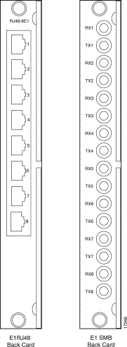
The MGX-AUSM-8T1/B and MGX-AUSM-8E1/B use the generic 8-port T1 or E1 line modules that operate with the 8-port service modules. The standard T1 version of the back card has eight RJ-48 connectors. The standard versions of the E1 back card have either eight RJ-48 connectors or eight pairs of SMB connectors. To support 1:N redundancy through an MGX-SRM-3T3/B card set, special versions of the RJ-45 back card must exist in the system
Redundancy support for the AUSM requires an MGX-SRM-3T3/B card set and the special versions of the RJ-45 back cards that support redundancy. See Figure 4-34 and Figure 4-35 for illustrations of the back cards. Differences exist in certain aspects of redundancy support for the MGX-AUSM-8T1/B and MGX-AUSM-8E1/B. For details on the requirements for redundancy through an MGX-SRM-3T3/B, refer to the section in this chapter titled "Service Resource Module."

This section describes installation requirements that are particular to the various types of Frame Service Modules (FRSMs). For hardware and other specifications on the FRSMs, refer to "System Specifications." For descriptions of how to configure the card, lines, and ports and add Frame Relay connections, refer to "Card and Service Configuration." The supported FRSM front cards and related back cards are:
An FRSM can reside in any slot except 7, 8, 15, 16, 31, and 32. In addition, any card for which you specify 1:N redundancy through the redundancy bus and the MGX-SRM-3T3/B cannot go in slot 9, 10, 25, or 26. Whenever possible, the VHS cards should go in the upper bay of the card cage because the upper half of the backplane provides higher bandwidth at each slot.
FRSM-VHS supports Frame Relay services on a T3, E3, or HSSI interface. (The collective name for the MGX-FRSM-2CT3, MGX-FRSM-2T3E3, and MGX-FRSM-HS2 is Very High Speed Frame Service Modules—FRSM-VHS for short). The distinction between the front cards is the firmware operation. The FRSM-VHS group consists of:
Example illustrations of the FRSM-VHS front and back cards appear in the figures that follow.


The MGX-FRSM-HS1/B supports four V.35 or four X.21 ports. Each port can operate in DTE or DCE mode. The mode depends on the type of attached cable. The information in this section lets you determine the correct cabling for the intended mode of each port. For a description of card, line, and port configuration, see "Card and Service Configuration." An illustration of the MGX-FRSM-HS1/B front card appears in Figure 4-42. The multifunction 12IN1-S4 back card appears in Figure 4-43. Cabling descriptions follow Figure 4-42.
 |
Note The MGX-FRSM-HS1/B does not support redundancy, so redundancy is not a consideration for deciding on a slot for the card. Nevertheless, it should be in the lower bay due to cell bus speed. |

The cable models come from the Cisco 12IN1 series of cables. (See Table 4-2.) Each cable can have a male or female connector at the far end. Also, the available clock sources depend on the mode. In DTE mode, the clock source is either line or ST (ST is a wire in the cable). For DCE, the clock source is the front card. See Table 4-3 for the relationship between cabling and modes and Table 4-4 for part numbers.
| Cable Type | X.21 | V.35 |
|---|---|---|
DCE | X.21 DCE | V.35 DCE |
DTE | X.21 DTE | V.35 DTE |
| Mode | Type of Cable | Clock Source | Mode of Far End |
|---|---|---|---|
DTE | DTE | line | DCE (male or female connector at far end) |
DCE | DCE | internal | DTE (male or female connector at far end) |
DTE_ST | DTE | ST line | DCE (male or female connector at far end) |
| Type of Cable | Far End Connector | Part Number |
|---|---|---|
X.21 DTE | male (standard) | 72-1440-01 |
X.21 DCE | female (standard) | 72-1427-01 |
V.35 DTE | male (standard) | 72-1428-01 |
V.35 DTE | female (atypical) | 72-1436-01 |
V.35 DCE | female (standard) | 72-1429-01 |
V.35 DCE | male (atypical) | 72-1437-01 |
V.35 DTE-DCE |
| 72-1441-01 |
Straight-through |
| 72-1478-01 |
Loopback plug |
| 72-1479-01 |
 |
Note The cable type and part number are printed on a plastic band located near the smaller connector. |

The eight-port FRSMs support channelized or unchannelized service on either T1 or E1 lines.
Figure 4-44 (applies to both MGX-FRSM-8T1 and MGX-FRSM-8E1), and Figure 4-45 and Figure 4-46 (primary and redundant back cards for T1 and E1) show these cards.


1
FRSMs can have either hot standby, 1:1 redundancy or 1:N redundancy. For 1:1 redundancy, a Y-cable is necessary. The very high speed MGX-FRSM-2CT3, MGX-FRSM-2T3E3, and MGX-FRSM-HS2 use Y-cable redundancy. For 1:N redundancy, an MGX-SRM-3T3/B (but no Y-cabling) are required. Differences may exist in the way the MGX-SRM-3T3/B supports redundancy for a particular T1 or E1 configuration. Refer to the section titled "Service Resource Module" in this chapter and the Service Resource Module description in "Card and Service Configuration."
For 1:1 redundancy, place the card sets in adjacent slots and connect a Y-cable for each pair of active and standby ports. On the CLI, configure the card for redundancy by executing the addred command. For instructions on how to use the CiscoView application to configure redundancy, refer to the CiscoView user-documentation.
A 1:N redundancy for the 8-port FRSMs requires an MGX-SRM-3T3/B. With 1:N redundancy, a group of service modules includes one standby module. For installation requirements, see the "Service Resource Module" section in this chapter. For configuration requirements, see the section on the MGX-SRM-3T3/B in "Card and Service Configuration."
The 8t-port models AX-CESM-8T1 and AX-CESM-8E1 let you configure individual physical ports for structured or unstructured data transfer. A card set has an AX-CESM-8T1 or AX-CESM-8E1 front card and one of the following back cards:
Redundancy for the AX-CESM-8T1 and AX-CESM-8E1 is available through the MGX-SRM-3T3/B. The support is 1:N and so requires that the group contain one redundancy back card. The redundancy back card must be the special R-RJ45 version. For information on installation requirements, refer to the "Service Resource ModuleG" section. For configuration requirements, see the section on the SRM in "Card and Service Configuration." For instructions on how to use the CiscoView application to configure redundancy, refer to the CiscoView user-documentation.

The description of the LEDs on the 8-port CESM front card appear in Table 4-5.
| Type of LED | Color | Meaning |
|---|---|---|
PORT LED | Green | Green indicates the port is active. |
| Red | Red indicates a local alarm on the port. |
|
| Off indicates the port has not been activated (upped). |
ACTIVE LED | Green | On indicates the card set is in active mode. |
STANDBY LED | Yellow | Slow blink without the Active LED indicates the card is in the boot state. |
|
| Fast blink with the Standby LED indicates the card is being downloaded. |
|
| Fast blink indicates the service module is passing BRAM channel information to the PXM1 |
|
| Steady yellow indicates the card is in Standby mode and the firmware is executing ADMIN code. |
FAIL LED | Red | Steady Red with Active and Standby LEDs off indicates either the card is in the Reset condition, the card has failed, or the card set is not complete (no line module). |
|
| Steady Red with Active LED on indicates the card was active prior to failing. |
|
| Steady Red with Standby LED on indicates the card was standby prior to failing. |
|
| Both standby and red LED lit indicates self test failure. |


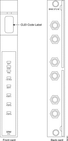
This section describes the possible impact of installing a Service Resource Module-3T3 (MGX-SRM-3T3/B) on the service modules it supports. The MGX-SRM-3T3/B (or "SRM" for short) can provide 1:N redundancy for the T1 and E1 cards as well as bulk distribution for T1 cards. It has no communication with higher-speed service modules, such as the MGX-FRSM-2CT3 and MGX-FRSM-HS2. See Figure 4-50 for an illustration of the MGX-SRM-3T3/B front card and the MGX-BNC-3T3-M back card.
The multifunction SRM has the following capabilities:
The following are card-level characteristics that apply to any SRM installation:
The use of bulk distribution affects the requirements for SRM and service module back cards:
For bulk distribution, the T3 lines connect to an external multiplexer. The T1 lines on the other side of the multiplexer connect to the CPE. The SRM converts the received traffic from its T3 lines to T1 channels and sends the data to linked service modules. For instructions on linking T1 channels and card slots to the MGX-SRM-3T3/B, see "Card and Service Configuration."
For bulk distribution of T1 lines, note the following about the MGX-SRM-3T3/B:
 |
Note Upon replacing the failed card, you must switch back to normal operation because the switch does not automatically do so. |
Copper-based data cables from the back cards run up or down to the cable manager and pass through the channels then run to either the left or right side of the rack. Fiber optic cables pass over the sheet metal portion. The cables subsequently go to the related equipment (CPE, for example). The view in Figure 4-51 shows only the cable manager on top.

Before applying power to the MGX 8250 switch, check the following items:
1. Switch has proper grounding.
2. AC or DC power sources are correctly installed.
3. All cards are locked in the correct slots.
4. All cables are secure.
5. Control terminal is connected.
After the preceding checks, turn on the power. Check the following:
1. At the front of the unit, the status light on the PXM1 should be green.
2. For an AC-powered system, the "AC" and "DC" LEDs on each power supply should be green.
3. For a DC-powered system, the "DC OK" LED should be on.
4. After each service module comes up, the status LED should show that the card is in standby.
5. When power is turned on, make a visual check to verify that all fans are running.
6. After the system comes up, execute the dsppwr command.
 |
Note Neither the AC power supplies nor any other components have test points for checking power supply voltages. For a visual check, observe whether the AC OK LED and DC OK LED are lit. |
 |
Note If you remove and reseat a back card or change it for another card, reset the related front card. |
The wiring on the Cisco MGX 8250 backplane requires you to consider the conversion sequence and other details when you convert single-height slots to double-height slots. One slot conversion means that you convert four single-height slots to two double-height slots. Be aware of the following before you convert the slots:
With a factory-installed Cisco MGX 8250 switch, the single- and double-height cards reside in the preassigned locations. Refer to Figure 4-52 for an illustration of an enclosure that shows installed cards and center guide modules. Certain slots have a small, L-shaped bracket holding in the card. All instances of this bracket are the card slots immediately to the right of an enclosure wall (or bulkhead). The system has three such brackets.
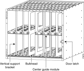
Each center guide module is secured by either a vertical support bracket or a simpler support bracket. Most center guide modules rely on the vertical support bracket. Three locations use the small support bracket: at the left wall of the card cage and at the bulkhead to the right of slot 8 or slot 14. For an illustration of a center guide module with support bracket, see Figure 4-54. For an illustration of a center guide module with vertical support bracket, see Figure 4-53.
 |
Warning Use extreme caution when executing the following steps with system power turned on. |
To convert four single-height slots to two double-height slots in an operational system:
Step 1 Remove the cabling from the back card unless the back card applies to the double-height configuration after the conversion.
Step 2 Remove the back card.
Step 3 Remove the front card.
Step 4 Repeat steps 2 and 3 for every other single-height module you remove.
Step 5 Rotate the screw that holds in the vertical center guide module.
Where either the left wall of the card cage or a bulkhead exists on the left of the single-height card slots, a simple, L-shaped bracket holds in the center guide module.
Step 6 If the center guide module has either type of wall to the left, unscrew the track attached to the wall. If necessary, remove cards to unscrew it.
Step 7 Remove the vertical support bracket by moving it up and down until you can take it out. A hole becomes visible in the center guide module for inserting a screw driver.
Step 8 Insert a screw driver and loosen the long screw that holds in the center guide module.
Step 9 Remove the center guide module.
Step 10 Install the double-height front card and back cards as needed.
A simpler situation exists when you install a new MGX 8250 switch in a non-Cisco rack or an existing Cisco cabinet: just unscrew the center guide module and remove it. If the enclosure has the optional front door, blank faceplates are not necessary. With no door, you must install a blank faceplate if you create two double-height slots but install only one card.


![]()
![]()
![]()
![]()
![]()
![]()
![]()
![]()
Posted: Tue Oct 1 08:24:41 PDT 2002
All contents are Copyright © 1992--2002 Cisco Systems, Inc. All rights reserved.
Important Notices and Privacy Statement.