|
|

This chapter describes how to configure the MGX 8250 cards and the services they support. Although the presumption for this chapter is that a plan exists for your network, it reviews some of the information that supports network planning. Generic instructions for inserting and removing cards appear in ""Enclosure and Card Installation."
The services and applicable modules described in this chapter are:
 |
Note For information on the Route Processor Module (RPM), see the Cisco Route Processor Module Installation and Configuration Guide. |
This section contains a general description of the sequence of tasks for configuring the cards and their services. It also contains details on how to configure resource partitions and add local connections and three-segment connections. Detailed descriptions of these tasks for individual cards appear in subsequent sections.
The current network control application is Portable AutoRoute (PAR). Planning considerations should include the possibility of modifying the partitioning of resources for the interface. For example, the MGX 8250 switch has the capacity to support a Cisco Multiprotocol Label Switching (MPLS) controller or a Private Network to Network Interface (PNNI) controller.
In a new switch, the common approach is to configure the same aspect for all cards at once—adding logical ports to all applicable cards, for example. In contrast, the likely sequence for installing a single card is to begin with its card-level features and continue until you have configured every connection. The common tasks for a new switch are
1. Optionally configure the service modules (except the RPM) for redundancy. This card-level operation requires redundant cards and possibly an MGX-SRM-3T3/B.
2. Optionally configure resource partitioning for the whole card if the default partitioning does not fulfill the purpose of the card.
3. Activate physical lines.
4. Configure the line if default parameters are not appropriate.
5. Create the logical ports then modify them as needed.
6. Optionally configure resource partitions for a logical port if the default partitioning does not support the intended operation of the port.
7. Add connections then modify them as needed.
This section describes the rules for adding local connections, three-segment connections, and management connections. The MGX 8250 switch can support:
A management connection is an inband IP connection that lets a workstation control a local or remote MGX 8250 switch through a service module rather than the Ethernet port on a PXM-UI. Although the rules include references to CLI syntax, they also apply to the Cisco WAN Manager application.
A DAX con is a connection whose end points for the entire connection exist on the same switch. The following apply to the MGX 8250 switch:
1. On a feeder, a DAX con can exist between different service modules or the same service module.
2. A stand-alone switch supports DAX cons with one or both end points on the PXM1 in addition to DAX cons between service modules.
3. Either end-point can be the master.
4. The first end-point to add is the slave. The generic syntax is:
5. If the end-point is a PXM1 port in a stand-alone switch, specify the slot as 0. The addcon command is the only command in which you specify the slot number for the PXM1 as 0.
A three-segment connection consists of a local segment on each MGX 8250 switch at the edges of the network cloud and a middle segment across the network cloud. The MGX 8250 requirements are as follows:
1. For MGX 8250 feeders, the backbone must consist of BPX 8600series switches.
2. For MGX 8250 stand-alone switches, the backbone switches can be either BPX 8600series switches or switches from another manufacturer.
3. On a feeder, the local segment exists between a service module and the PXM1.
4. On a stand-alone switch, the local segment can be between a service module and a port on the PXM1 or just two ports on the PXM1.
5. For the local segment, add the connection at only the master end-point. The generic syntax is
This section describes the requirements for adding an inband ATM PVC for managing an MGX 8250 stand-alone switch. A management connection lets a workstation connected through a router control either the local MGX 8250 switch or a remote MGX 8250 switch that has no workstation. The typical configuration has the connecting router feed an AUSM/B, FRSM, RPM, or PXM1 UNI port.
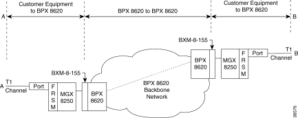
A management connection can be either a DAX con or a three-segment connection. The maximum number of management connections is eight. The DAX con exists between a service module or PXM1 UNI and port 34 of the local PXM1. PXM1 port 34 is a reserved port for management connections on a stand-alone switch. The network in Figure 6-1 shows FRSMs in a feeder application.
A three-segment management connection has a:
1. Local segment between a near-end service module or PXM1 UNI and a PXM1 port in the
range 1-32.
2. Middle segment across the network cloud.
3. Local segment between a remote PXM1 port in the range 1-32 and port 34 of that same PXM1.
The path from "A" to "B" in Figure 6-1 consists of three segments. A segment exists between the FRSM and the PXM1 on each MGX 8250 switch. The middle segment exists between the BXMs at the edges of the ATM cloud and may traverse BPX 8600 via switches in the cloud. The VPI and VCI at each BPX8600 series switch connected to an MGX 8250 feeder must match the VPI and VCI on the slave end-point of the connected PXM1. The VPIs and VCIs at the end-points of the middle segment do not have to match. If you use the CLI rather than the Cisco WAN Manager application, add each segment through the CLI at each switch.
This section first describes how to activate and configure the card-level parameters, lines, and ports on the PXM1 uplink card then describes how to add connections to the PXM1 in a stand-alone switch. The descriptions tell you how to:
|
Note For a description of the bit error rate test (BERT) functions, see the section titled "Bit Error Rate Testing Through an MGX-SRM-3T3." |
This section defines the clock sources for the MGX 8250 switch, then describes how to configure each source.
The available clock sources are as follows:
After the PXM1 broadband interfaces and the service module lines have been configured, you can configure the clock sources through the CiscoView application or the CLI. If you use the CLI, execute cnfclksrc on the active PXM1 one time for each clock source:
cnfclksrc <slot.port> <clktyp>
The parameter slot.port specifies the clock source. If a service module provides the source, slot is the slot number of the card, and port is the number of the line that provides the clock.
On the PXM1:
The value for clktyp is P for primary, S for secondary, T for tertiary, or N for null. The only purpose of null is to remove the clock configuration that currently applies to the specified source (slot.port).
 |
Caution Be careful not to set multiple primaries and secondaries. |
For example, to configure the inband interface as the primary clock source and an external clock device as the secondary source, execute the following two commands.
For an external clock source:
popeye1r.1.8.PXM.a > cnfclksrc 7.35 P
For an internal clock source:
popeye1r.1.8.PXM.a > cnfclksrc 7.1 S
Check the configuration by executing dspclksrc.
If you have specified an external clock source, use the CiscoView application or the CLI command cnfextclk to select the T1 or E1 line and the impedance of the line. The syntax for cnfextclk is:
cnfextclk <ClockType> <Impedance>
ClockType can be 1 for T1 or 2 for E1. Impedance can be 1 for 75 ohms, 2 for 100 ohms, or 3 for 120 ohms.
This section describes how to configure card-level features, activate a physical line, and configure logical elements such as a port. If necessary, refer to the section titled "Tasks for Configuring Cards and Services" for background information on these types of tasks.
Step 1 Optionally, you can modify the resource partitioning for the whole card by executing cnfcdrscprtn. You can view resource partitioning through dspcdrscprtn.
cnfcdrscprtn <number_PAR_conns> <number_PNNI_conns> <number_TAG_conns>
For example, you could reserve 10,000 connections for each controller on a PXM1 with:
cnfcdrscprtn 10000 10000 10000
Step 2 Activate a line by executing addln:
addln -ds3 <slot.line> | -e3 <slot.line> | -sonet <slot.line>
For a feeder, you can activate only one line. For a stand-alone, you can activate more than one line if the back card has multiple lines. One line must serve as the trunk to the ATM network. With an OC-3, T3, or E3 card, remaining lines can serve as UNI ports to CPE.
Step 3 If necessary, modify the characteristics of a line by using cnfln.
Step 4 Configure logical ports for the physical line by executing addport. Execute addport once for each logical port. Related commands are cnfport, dspports, and delport.
addport <port_num> <line_num> <pct_bw> <min_vpi> <max_vpi>
Using an example of 100% of the bandwidth on one logical port 1:
addport 1 1 100 1 200
where the first "1" is the logical port number; the second "1" is the line number on the PXM back card to which you are assigning this logical port number; "100" is the percentage of bandwidth this port has in both directions; and the VPI range is 1-200.
Step 5 If necessary, use cnfportrscprtn to modify port-level resources for a controller:
cnfportrscprtn <port_no> <controller> <ingress_%BW> <egress_%BW>
Step 6 On a stand-alone switch, specify the cell header type as needed by executing cnfatmln.
cnfatmln <line_num> <type>
UNI cell headers typically apply where a workstation connects through a line to a PXM UNI port (rather than a SLIP-based port on the PXM-UI card). Such an implementation is not common, so cnfatmln usually is not necessary.
Step 7 Configure the 12IN1 dual-personality back card to be either V.35 or X.21 service by executing cnfbctype.
cnfbctype <cardType>
1 = X.21
2 = V.35
If the cnnfbctype command is never issued, the default back card type is V.35.
dspbctype
Automatic Protection Switching (APS) provides redundancy for an OC-3 or OC-12 line on the PXM1 if a failure occurs someplace other than the PXM1 front card. The failure can originate on the daughter card, uplink card, or any part of the physical line. With APS, the active PXM1 remains active and passes the cells from the failed line-path through the redundant line. The advantage of APS is that a line switchover requires significantly less time than a full PXM1 switchover. (A failure of the PXM1 front card in a redundant system causes the entire PXM card set to switch over.) As defined in GR-253, a variety of APS modalities are possible (see command summaries that follow).
The current requirements for APS service on an MGX 8250 switch are
Initial APS specification consists of the working and protection slot and line and the mode for APS. After the initial APS specification, you can configure additional APS parameters, give commands for switching lines, and display the APS configuration. The CiscoView application and CLI provide access to the APS feature. For detailed descriptions of the CLI commands, see the Cisco MGX 8000 Series Command Reference. Note that APS is available only for the "B" versions of the SONET cards—SMLR-1-622/B, and so on. The applicable CLI commands are:
To specify APS, use the following syntax:
addapsln <workline> <workingslot> <protectionline> <protectionslot> <archmode>
where workline and workingslot identify the line and slot of the APS working line, and protectionline and protectionslot identify the protection line and slot. According to GR-253, the archmode identifies the type of APS operation. The mode definition includes:
1. 1+1 on one back card
2. 1+1 on two back cards
3. 1:1
4. Annex B
Currently, the only supported mode is 1+1 with two uplink cards (mode=2). With 1+1 APS, both the working line and the protection line carry duplicate data even though no error threshold has been exceeded or line break has occurred. This mode requires that two standard cables (rather than a Y-cable) connect at two ports on the equipment at the opposite end. With the two-card implementation, workline must be the same as protectionline.
This section describes the CLI commands for provisioning connections on a PXM1 in a stand-alone switch. Connection addition conforms to the rules for a standard connection or a management connection. (See "Rules for Adding Connections" earlier in this chapter.) In addition, this section describes the commands for modifying specific features for a connection and policing connections by way of usage parameter control (UPC).
The CLI commands correspond to functions in the Cisco WAN Manager application. The preferred CLI command is addcon. (If the application requires NSAP addressing, use addchan to add a connection and cnfchan to modify a connection. To see the syntax for these two commands, refer to the command reference.) On the PXM1 CLI:
Step 1 Execute the addcon command according to the following syntax:
addcon <port_num> <conn_type> <local_VPI> <local_VCI> <service> [CAC] [mastership] [remoteConnId]
|
Note The slot number of the active PXM1 is always 0 when you add a connection. |
Step 2 If necessary, modify a connection by using cnfcon:
cnfcon <conn_ID> <route_priority> <max_cost> <restrict_trunk_type> [CAC]
Step 3 As needed, specify usage parameter control according to the connection type. Use either cnfupccbr, cnfupcvbr, cnfupcabr, or cnfupcubr. This step defines the parameters for each of these commands. Note that the parameters for cnfupcvbr and cnfupcabr are the same. Also, the polType parameter has numerous variations in accordance with ATM Forum v4.0. For a list of these variations, see Table 6-1 after the syntax descriptions.
cnfupccbr <conn_ID> <polType> <pcr[0+1]> <cdvt[0+1]> <IngPcUtil> <EgSrvRate> <EgPcUtil>
cnfupcvbr or cnfupcabr <conn_ID> <polType> <pcr[0+1] <cdvt[0+1]> <scr> <mbs> <IngPcUtil> <EgSrvRate> <EgPcUtil>
cnfupcubr <conn_ID> <polType> <pcr[0+1] < cdvt[0+1]> <IngPcUtil>
| Policing by Connection Type | ATM Forum TM spec. 4.0 conformance definition | PCR Flow (1st leaky bucket) | CLP tagging (for PCR flow) | SCR Flow (2nd leaky bucket) | CLP tagging (for SCR flow) |
|---|---|---|---|---|---|
CBR polType=4 | CBR.1 (PCR Policing only) | CLP(0+1) | no | off | n/a |
CBR polType=5 | When policing=5 (off) | off | n/a | off | n/a |
UBR polType=3 | UBR.1 when CLP setting=no | CLP(0+1) | no | off | n/a |
UBR polType=4 | UBR.2 when CLP setting=yes | CLP(0+1) | no | CLP(0) | yes |
UBR polType=5 | Policing is off | off | n/a | off | n/a |
VBR and ABR polType=1 | VBR.1 1 | CLP(0+1) | no | CLP(0+1) | no |
VBR and ABR polType=2 | VBR.2
| CLP(0+1) | no | CLP(0) | no |
VBR and ABR polType=3 | VBR.3
| CLP(0+1) | no | CLP(0) | yes |
VBR and ABR polType=4 | (when Policing=4) | CLP(0+1) | no | off | n/a |
VBR and ABR polType=5 | Policing is off | off | n/a | off | n/a |
The 8-port ATM Universal Service Module (MGX-AUSM/B-8T1 and MGX-AUSM/B-E1) is a multipurpose card set with eight T1 or E1 lines that support:
You can activate and configure the card, the lines, and the ports on the AUSM series cards through the CiscoView application or the CLI. To perform connection-related tasks, use the Cisco WAN Manager application or the CLI. Refer to the documentation for these applications for task descriptions. Use the commands described in this section to:
On the CLI of the AUSM/B:
Step 1 If necessary, modify the resource partitioning for the whole card by executing the cnfcdrscprtn command. You can view resource partitioning through dspcdrscprtn.
cnfcdrscprtn <number_PAR_conns | number_PNNI_conns | number_TAG_conns>
For example, you could reserve 300 connections for each controller on the AUSM with:
cnfcdrscprtn 300 300 300
Step 2 Activate a physical line by using addln for each of the eight lines as needed:
addln <line_number>
Step 3 Optionally, use the cnfln command to specify line coding, line length, and clock source:
cnfln <line_num> <line_code> <line_len> <clk_src> [E1-signalling]
Step 4 Execute upport to activate the logical operation of the line:
upport <port_number>, where port_number is in the range 1-8.
Step 5 If necessary, execute cnfportq to modify the egress queues:
cnfportq <port_num> <q_num> <q_algo> <q_depth> <clp_high> <clp_low> <efci_thres>
port_num | is the logical port number in the range 1-8. |
q_num | is the queue number in the range 1-16; 0 is the default for addchan. 1=CBR |
q_algo | is a number to specify the queue algorithm: 0=disable queue |
q_depth | is the maximum queue depth in the range 1-16000 cells. |
clp_high | is the high cell loss priority in the range 1-16000 cells. |
clp_low | is the low cell loss priority in the range 1-16000 cells. |
efci_thres | is the EFCI threshold in the range 1-16000 cells. |
Step 6 If necessary, configure resources at the port level by executing cnfportrscprtn. Use dspportrscprtn to see the current resource partitioning.
cnfportrscprtn <port_num> <controller> <ingress_%BW> <egress_%BW> <number_of_cons> <VPImin/VPImax> [VCImin/VCImax]
The command sequence for configuring the IMA feature:
Step 1 addln on all constituent links.
Step 2 cnfln if necessary.
Step 3 addimagrp (or addaimgrp) to create the IMA group by using the following syntax:
addimagrp <group_num> <port_type> <list_of_links> <minNumLink>
group_num | is a number for IMA group. The range is 1-8. |
port_type | is the port type: 1=UNI, 2=NN1. |
list_of_links | is the list of links to be included in the group. Separate each link number by a period. |
minNumLink | is the minimum number of links in the range 1-8 to form a group. |
For example: the following creates IMA group 1 with lines 3, 4, and 5. The minimum is 3.
addimagrp 1 3.4.5 3
IMA-related commands are dspimagrp, dspimagrpcnt, dspimagrps, dspimainfo, and dspimalncnt. Refer to the Cisco MGX 8800 Series Switch Command Reference for descriptions.
You can add and modify connections through the Cisco WAN Manager or the CLI. Refer to applicable documentation if you use the WAN Manager application. This section describes how to add an ATM connection through the CLI according to the rules for adding a standard connection or a management connection in the form of either a DAX con or a three-segment connection. See "Rules for Adding Connections" earlier in this chapter.
On the CLI of the AUSM/B:
Step 1 Execute the addcon command.
When you add a connection with addcon, the system automatically assigns the next available channel number, so addcon does not require it. However, some related commands require a channel number—cnfchanfst, cnfchanq, and cnfupcabr, for example. To see the channel number after you add a connection, use dspcons.
The addcon syntax is:
addcon <port_number> <vpi> <vci> <ConType> <SrvType> [Controller_Type] [mastership] [remoteConnID]
port number | port number is in the range 1-8. |
vpi | VPI has a value in the range 0-255. |
vci | VCI can be in the range 0-65535 for a VCC or * for a VPC. |
Conn type | is the connection type: 0=VCC, and non-0 is the local ID of a VPC in the range 1-1000. |
Service Type | is the service type: 1=CBR, 2=VBR, 3=ABR, and 4=UBR. |
mastership | is the mastership status of the end-point. 1=master, and 2=slave. The default is slave, so you actually do not need to type a 2. |
Controller_Type | is the optional controller specification. 1=PAR (the default} |
connID | is entered at only the master end and consists of the switch name, slot number, port number, VCI, and VPI of the slave end. |
Step 2 To configure usage parameter control (UPC) for the connection (channel), use cnfupccbr, cnfupcvbr, cnfupcabr, or cnfupcubr. Use dspcons to obtain the channel number.
cnfupccbr <port.vpi.vci> <enable/disable> <pcr[0+1]> <cdvt[0+1]> <IngPcUtil> <EgSrvRate> <EgPcUtil>
port.vpi.vci | identifies the connection. |
enable/disable | is the UPC enable: 1=disable, 2=enable. |
pcr[0+1] | is the peak cell rate. Without IMA, the range is as follows: T1, 10-3622 cells per second For IMA, multiply the line rate by the number of links. |
cdvt[0+1] | is the cell delay variation tolerance for cells with CLP=0 and CLP=1. The range is 1-250000 micro seconds. |
IngPcUtil | is the percent utilization on the ingress. The range is 1-127. The default is 0. |
EgSrvRate | is the egress service rate. Without IMA, the range is as follows: T1, 10-3622 cells per second For IMA, multiply the line rate by the number of links. |
EgrPcUtil | is the percent utilization on the egress. The range is 1-127. |
cnfupcvbr has the same syntax and parameters as cnfupcabr
cnfupcvbr or cnfupcabr <port.vpi.vci> <enable> <pcr[0+1]> <cdvt[0+1]> <scr> <scr_police> <mbs> <IngPcUtil> <EgSrvRate> <EgPcUtil> <clp_tag>
port.vpi.vci | identifies the connection. |
enable | is the enabled/disable for UPC: 1=Disable, 2=Enable. |
pcr | is the peak cell rate. Without IMA, the range is as follows: T1, 10-3622 cells per second For IMA, multiply the line rate by the number of links. |
cdvt | cdvt[0+1] is the cell delay variation tolerance for cells with CLP=[0+1]. The range is 1-250000 microseconds. |
scr | is the peak cell rate. Without IMA, the range is as follows: T1, 10-3622 cells per second For IMA, multiply the line rate by the number of links. |
scr_police | specifies the type of scr policing: 1= CLP[0] cells, |
mbs | is the maximum burst size: the range is 1-5000 cells. |
IngPcUtil | is the percent utilization on the egress. The range is 1-127. The default is 0. |
EgSrvRate | is the egress service rate. Without IMA, the range is as follows: T1, 10-3622 For IMA, multiply the line rate by the number of links. |
EgrPcUtil | is the percent utilization on the ingress. The range is 1-127. The default is 0. |
clp_tag | is the enable for CLP tagging: 1=disable, 2=enable. |
cnfupcubr <port.vpi.vci> <enable> <pcr[0+1]> <cdvt[0+1]> <IngPc> <util> <clp_tag>
port.vpi.vci | identifies the connection. |
enable | is the enabled/disable for UPC: 1=Disable, 2=Enable. |
pcr | is the peak cell rate. Without IMA, the range is: T1, 10-3622 For IMA, multiply the line rate by the number of links. |
cdvt | cdvt[0+1] is the cell delay variation tolerance for cells with CLP=[0+1]. The range is 1-250000 microseconds. |
scr | is the peak cell rate. Without IMA, the range is: T1, 10-3622 For IMA, multiply the line rate by the number of links. |
scr_police | specifies the type of scr policing: 1= CLP[0] Cells, |
mbs | is the maximum burst size: the range is 1-5000 cells. |
IngPc | is the percent utilization on the ingress. The range is 1-127. The default is 0. |
hclp_tag | is the enable for CLP tagging: 1=disable, 2=enable. |
Step 3 If the system has the ForeSight feature, use cnfchanfst to configure it.
cnfchanfst <port.vpi.vci> <enable> <fgcra_enable> <ibs> <pcr> <mcr> <icr>
port.vpi.vci | identifies the connection. |
enable | is the enabled/disable for the ForeSight feature: |
fgcra_enable | is the enabled/disable for the frame-based generic cell rate algorithm: 1=disable, 2=enable. |
ibs | is the initial burst size in the range 0-5000 cells. |
pcr | is the peak cell rate. Without IMA, the range is: T1, 10-3622 For IMA, multiply the line rate by the number of links. |
mcr | is the minimum cell rate. Without IMA, the range is: T1, 0-3622 For IMA, multiply the line rate by the number of links. |
icr | is the initial cell rate. Without IMA, the range is as follows: T1, 0-3622 For IMA, multiply the line rate by the number of links. |
Step 4 If necessary, change the queue depths by using cnfchanq.
cnfchanq <port.vpi.vci> <discard_option> <vc_q_depth> <clp_thresh_high> <clp_thresh_low | epd_threshold> <efci_thresh>
port.vpi.vci | identifies the connection. |
discard_option | is either 1 for CLP hysteresis or 2 for framebased. |
vc_q_depth | is the ingress queue depth in the range 1-16000 cells. |
clp_thresh_high | is the CLP high threshold in the range 1-16000 cells. |
clp_thresh_low or epd_threshold | is the CLP low threshold in the range 1-16000 cells for CLP hysteresis-based discard. or is the EPD threshold in the range 1-16000 cells frame-based discard.
|
efci_thresh | is the EFCI threshold in the range 1-16000 cells. |
For the middle segment, be sure to use the connection type as the local segments on the MGX 8250 switch (CBR, VBR, ABR, or UBR). The parameters directly map from those specified at the connection end-point.
This section describes the features available on each of the Frame Service Modules (FRSMs). For descriptions of how to set up these cards and add connections, see the subsequent section titled "Configuring Frame Relay Service." This section consists of:
The primary function of the FRSM is to convert between the Frame Relay-formatted data and ATM/AAL5 cell-formatted data. For an individual connection, you can configure network interworking (NIW), service interworking (SIW), ATM-to-Frame Relay UNI (FUNI), or frame forwarding. An FRSM converts the header format and translates the address for:
The models of the FRSM include 8-port T1 and E1 cards and very highspeed modules. Higher speed modules support unchannelized E3 and HSSI as well as channelized and unchannelized T3.
The Very High Speed Frame Service Modules (FRSM-VHS) support Frame Relay services on T3, E3, and HSSI interfaces. Up to 24 FRSM-VHS cards in any combination can operate in the switch. They should occupy upper slots whenever possible. The FRSM-VHS group on an MGX 8250 switch consists of:
|
Note Subrate capability is not supported on Kentrox equipment. |
The AX-FRSM-8T1 and AX-FRSM-8E1 provide unchannelized Frame Relay service for up to 1000 connections on eight T1 or E1 lines. The AX-FRSM-8T1c and AX-FRSM-8E1c provide channelized service for up to 1000 connections. Fewer connections are possible with any form of LMI.
The MGX-FRSM-HS1/B provides unchannelized Frame Relay service on a maximum of 200 connections across four V.35 or X.21 interfaces. The maximum throughput for the card is 16 Mbps. The maximum rate on one line is 8 Mbps. Without the cost of a T3 or E3 card, the MGX-FRSM-HS1/B provides greater than T1 or E1 speeds on a port as well as a choice of 50 line rates in a range of 48 Kbps-8 Mbps.
This section first lists the features common to all FRSM models, then lists the features of each model. All FRSMs support:
|
Note Subrate capability is not supported on Kentrox equipment. |
The specific features are:
The specific features are:
The specific features are:
The specific features and characteristics are:
The specific features are:
The following sections describe NIW, SIW, FUNI, and frame forwarding. Topics include translation and congestion management.
Frame Relay-to-ATM network interworking (NIW) supports a permanent virtual connection (PVC) between two Frame Relay users over a Cisco network or a multi-vendor network. The traffic crosses the network as ATM cells. To specify NIW for a connection, add the connection with a channel type of "network interworking." For an illustration of a BPX 8620 network with NIW connections, see Figure 6-2.
In addition to frame-to-cell and DLCI-to-VPI/VCI conversion, the NIW feature maps cell loss priority (CLP) and congestion information from Frame Relay-to-ATM formats. Subsequent sections contain the details. You can modify the CLP and congestion indicators for individual connections.
You can modify the CLP and congestion indicators for individual connections. On the CLI., use the cnfchanmap command. In the Frame Relay-to-ATM direction, you can configure each Frame Relay-ATM NIW connection for one of the following CLP-to-DE mapping schemes:
In the ATM-to-Frame Relay direction, you can configure each Frame Relay/ATM NIW connection for one of the following CLP-to-DE mapping schemes:
Congestion on the Frame Relay/ATM network interworking connection is flagged by the EFCI bit. The EFCI setting depends on the direction of the traffic. In the Frame Relay-to-ATM direction, EFCI is always set to 0. In the ATM-to-Frame Relay direction, the FECN bit of the Frame Relay frame is set if the EFCI field in the last received ATM cell of a segmented frame is set.
The management of ATM layer and FR PVC status management can operate independently. The PVC status from the ATM layer is used when determining the status of the FR PVC. However, no direct actions of mapping LMI A bit to OAM AIS is performed.
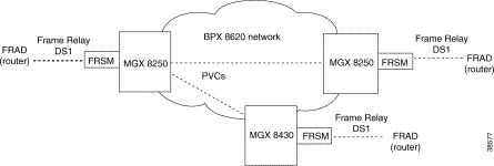
By specifying a service interworking (SIW) channel type when you add a Frame Relay PVC to an FRSM, all data is subject to SIW translation and mapping in both the Frame Relay-to-ATM and ATM-to-Frame Relay directions. A BPX 8620 network with SIW connections appears in Figure 6-3.

In Figure 6-3, an MGX 8250 switch on the right has three Frame Relay SIW connections terminating on an FRSM. Three far-end terminations for these connections appear in other parts of Figure 6-3:
In addition to frame-to-cell and DLCI-to-VPI/VCI conversion, SIW maps cell loss priority and congestion data between the Frame Relay and ATM formats and is FRF.8-compliant. It provides full support for routed and bridged PDUs, transparent and translation modes, and VP translation.
In addition to frame-to-cell and DLCI-to-VPI/VCI conversion, the SIW feature maps cell loss priority (CLP) and congestion information from the Frame Relay format to the ATM format for an individual connection. You can also modify the CLP and congestion indicators for a connection. On the CLI, use cnfchanmap for these tasks. In the Frame Relay-to-ATM direction, you can specify the discard eligibility (DE)-to-cell loss priority (CLP) mapping for an SIW connection:
In the ATM-to-Frame Relay direction, you can specify a CLP-to-DE mapping scheme for an individual connection:
This section describes congestion indictors. You can modify the CLP and congestion indicators for a connection. On the CLI, use the cnfchanmap command. In the Frame Relay-to-ATM direction for an individual SIW connection, you can configure the mapping for Forward Explicit Congestion Notification (FECN)-to-Explicit Forward Congestion Indicator (EFCI) schemes:
In the ATM-to-Frame Relay direction, service interworking connections use the following EFCI to FECN/BECN mapping schemes:
The FRSM provides command and response mapping in both directions:
Each service interworking (SIW) connection can exist in either translation or transparent mode. In translation mode, the FRSM translates protocols between the FR NLPID encapsulation (RFC 1490) and the ATM LCC encapsulation (RFC 1483).
In transparent mode, the FRSM does not translate. Translation mode support includes address resolution by transforming address resolution protocol (ARP, RFC 826) and inverse ARP (inARP, RFC 1293) between the Frame Relay and ATM formats.
You can configure an individual port for frame forwarding. Frame forwarding is the same as standard Frame Relay except that the FRSM:
All FRSMs support the ATM Frame User-to-Network Interface (FUNI). When a frame arrives from the FUNI interface, the FRSM removes the 2-byte FUNI header and segments the frame into ATM cells by using AAL5. In the reverse direction, the FRSM assembles ATM cells from the network into a frame by using AAL5, adds a FUNI header to the frame, and sends it to the FUNI port.
The FRSM maps the loss priority indication for both directions:
The FRSM maps congestion indication in both directions:
This section first describes how to configure the FRSM card, lines, and ports, then describes how to add connections. The descriptions are for the CLI execution of the tasks. You can also configure the FRSM card, lines, and ports by using the CiscoView application. Refer to the CiscoView documentation for the directions. Also, the easiest way to add connections is by using the Cisco WAN Manager application. For full details of how to set up a connection through the WAN Manager GUI, refer to the Cisco WAN Manager Operations manual.
This section describes how to configure card-level parameters—including Y-cable redundancy where applicable, physical lines, and logical ports on the FRSM-series cards.
Step 1 If necessary, modify the resource partitioning for the whole card by executing the cnfcdrscprtn command. You can view resource partitioning through dspcdrscprtn.
cnfcdrscprtn <number_PAR_conns | number_PNNI_conns | number_TAG_conns>
number_PAR_conns is the number of connections in the range 0-1000 available to the PAR controller.
number_PNNI_conns is the number of connections in the range 0-1000 available to a PNNI controller.
number_TAG_conns is the number of connections in the range 0-1000 available to the Tag controller.
For example, you could reserve 300 connections for each controller on the FRSM with:
cnfcdrscprtn 300 300 300
Step 2 If the physical line is not yet active, use the addln command to activate it. The only argument addln takes is the line number.
Step 3 If necessary, modify a line on the MGX-FRSM-2CT3, MGX-FRSM-HS2, MGX-FRSM-HD1/B, AX-FRSM-8T1 or AX-FRSM-8E1 by using cnfln.
To change the line parameters on an MGX-FRSM-2CT3 or MGX-FRSM-2T3E3, use cnfds3ln. Note that both cnfln and cnfds3ln apply to the MGX-FRSM-2CT3 but apply to different features. Refer to the Cisco MGX 8800 Series Command Reference for the syntax of the line modification commands on all cards except the MGX-FRSM-HS1/B.
The syntax for cnfln on the MGX-FRSM-HS1/B is:
cnfln <line_num> <line_type> <line_rate>
|
Note If no cable is attached, the system lets you specify any line type, but the Alarm LED on the front card turns from yellow to red. |
| 1-50 Correspond to Line Rates in Kbps. | ||||
|---|---|---|---|---|
1=48000 | 2=56000 | 3=64000 | 4=112000 | 5=128000 |
6=168000 | 7=192000 | 8=224000 | 9=256000 | 10=280000 |
11=320000 | 12=336000 | 13=384000 | 14=392000 | 15=448000 |
16=512000 | 17=768000 | 18=1024000 | 19=1536000 | 20=1544000 |
21=1792000 | 22=1920000 | 23=1984000 | 24=2048000 | 25=3097000 |
26=3157000 | 27=4096000 | 28=4645000 | 29=4736000 | 30=6195000 |
31=6315000 | 32=7744000 | 33=7899000 | 34=8192000 | 35=9289000 |
36=9472000 | 37=10240000 | 38=10890000 | 39=11059000 | 40=12390000 |
41=12629000 | 42=13897000 | 43=14222000 | 44=14336000 | 45=15488000 |
46=15799000 | 47=16384000 | 48=20025000 | 49=2498600 | 50=52000000 |
The possible errors for cnfln are:
Step 4 If the logical port does not exist or is not the appropriate type (Frame Relay, FUNI, or frame forwarding), execute addport to create the appropriate type of port. If the logical port already exists and needs no modification (cnfport), you can add connections by performing the tasks in "Adding a Frame Relay Connection." The parameters for addport depend on the type of FRSM:
For MGX-FRSM-2T3E3, or MGX-FRSM-HS2:
addport <port_num> <line_num> <port_type>
For an MGX-FRSM-2CT3:
addport <port_num> <line_num> <ds0_speed> <begin_slot> <num_slot>
<port_type>
For MGX-FRSM-HS1/B
addport <port_num> <port_type>
For AX-FRSM-8T1 and AX-FRSM-8E1:
addport <port_num> <line_num> <ds0_speed> <begin_slot> <num_slot> <port_type>
Step 5 Modify as needed the signaling on a port by executing cnfport.
cnfport <port_num> <lmi_sig> <asyn> <elmi> <T391> <T392> <N391> <N392> <N393>
Step 6 Configure resources for the port as needed by executing cnfportrscprtn. To see the partitioning, use dspportrscprtn. The description has a high- and low-bandwidth version:
cnfportrscprtn <port_num> <controller> <percent BW> <low DLCI> <high DLCI> <max LCN>
For FRSM-VHS and the MGX-FRSM-HS1/B cards:
For AX-FRSM-8T1 or AX-FRSM-8E1:
|
Note The following step applies to Y-cable redundancy for the MGX-FRSM-2T3E3. For 1:N redundancy on the 8-port FRSMs, refer to "Redundancy Support by the MGX-SRM-3T3/B." |
Step 7 Optionally configure Y-cable redundancy if you have connected the lines of adjacent MGX-FRSM-2T3E3 cards through a Y-cable. The applicable commands are addred, dspred, and delred. These commands run on the PXM1 rather than the service module, so you must change to the PXM1 CLI to execute them:
addred <redPrimarySlotNum> <redSecondarySlotNum> <redType>
Use the display commands dspcd, dspln, and so on to check the configuration and status.
This section describes how to add a Frame Relay connection according to the rules for adding a standard connection or a management connection in the form of either a DAX con or a three-segment connection. See "Rules for Adding Connections" earlier in this chapter.
Step 1 Add a connection by using addcon. If the application requires the NSAP form for the end-point, use addchan as described in the command reference.
The system automatically assigns the next available channel number, so the addcon command does not require it. However, some related commands require a channel number. To see the channel number after you add a connection, use dspcons.
On the FRSM-VHS cards (2CT3, 2T3E3, or HS2):
addcon <port> <DLCI> <cir> <chan_type> <egress_service_type> [CAC] <controller_type> <mastership> [connID] <controllerID>
Switchname.SlotNo.PortNo.DLCI
Switchname.SlotNo.PortNo.ControllerId.DLCI
Switchname.SlotNo.PortNo.VPI.VCI for ATM end-point
For AX-FRSM-8T1 and AX-FRSM-8E1:
addcon <port> <DLCI> <cir> <chan_type> [CAC] <controller_type> <mastership> <connID> <controllerID>
SwitchName.SlotNo.PortNo.DLCI
SwitchName.SlotNo.PortNo.ControllerId.DLCI
SwitchName.SlotNo.PortNo.VPI.VCI for ATM end-point
For MGX-FRSM-HS1/B:
addcon <port_number> <DLCI> <CIR> <chan_type> <CAC> <Controller_type> <mastership> <connID>
Step 2 Modify a connection as needed by executing cnfcon. See the command line Help or the command reference for the parameters for individual card types.
Step 3 If necessary, modify the CLP and congestion indicator fields by using cnfchanmap. Use dspchanmap to check this configuration for a connection.
cnfchanmap <chan_num> <chanType> <FECN/EFCI> <DE to CLP> <CLP to DE>
chan_num | is the channel (connection) number. The ranges are: 2CT3, 16-4015 |
|
|
chanType | is a number in the range 1-5 indicating the service type for 1=NIW |
FECN/EFCI | is a number in the range 1-2 that specifies the mapping between FECN and EFCI fields. 1=map EFCI (SIW only) |
DE to CLP | is a number in the range 1-3 that specifies the DE-to-CLP mapping. 1=map DE to CLP |
CLP to DE | is a number in the range 1-4 that specifies the CLP-to-DE mapping. 1=map CLP to DE |
Step 4 To check statistics for a connection, use dspchstats as needed.
For a three-segment connection, establish a BPX 8600 to BPX 8600 series (middle) segment. Execute addcon at one of the BPX 8600 series switchEs, as follows:
Specify the other addcon bandwidth parameters such as MCR, PCR, %Util, and so on.
For example: | AR equals 64K, PCR=237, or |
The preceding MCR and PCR formulae are predicated on a relatively small frame size of 100 octets, and even smaller frame sizes can result in worst-case scenarios. For example:
For a frame size of 64 octects the PCR formula becomes: | PCR = AR * 2/512 cells per sec |
For a frame size of 43 octects the PCR formula becomes: | PCR = AR * 2/344 cells per sec |
% Util should be set to the same value as that used for the Frame Relay segments of the connection.
To check the state of cards, lines, ports, queues, and connections, use the display commands (dsp...) and addchanloop. The following commands are available for testing the FRSMs (see the Cisco MGX 8800 Series Command Reference for descriptions):
The FRSM cards support card- and line-level alarm reporting. Use the CiscoView application or the CLI to view current alarms. The CLI commands are dspalmcnt, dspalm, and dspalms. These commands require a switch, either "-x21 or "-hs1" whichever is valid, to identify the interface type. See the MGX 8800 Series Command Reference for syntax and alarm descriptions.
The MGX 8250 switch can perform a bit error rate test (BERT) on one active line at a time on the MGX-FRSM-2T3E3. This type of testing disrupts service because it requires the tested path to be in loopback mode. You can configure a BERT session and perform related tasks through the CiscoView application or the CLI.
The MGX 8250 bus structure supports one BERT session per upper or lower bay of the card cage, so the switch can run a maximum of two sessions at once. When you specify the target slot through the CiscoView application or the acqdsx3bert command on the CLI, the system determines if a BERT configuration already exists in the bay that has the specified slot. If no BERT configuration exists in the bay, the display presents a menu for the BERT parameters.
The CLI commands (whose functions correspond to CiscoView selections) are:
Refer to the Cisco MGX 8250 Wide Area Edge Switch Command Reference for command details.
|
Note When a BERT session begins, all the connections on the line go into alarm and return to normal when you end the test. Consequently, the test may result in a large number of traps and other types of traffic (such as AIS). |
The main function of the Circuit Emulation Service Module (CESM) is to provide a constant bit rate (CBR) service. The CESM converts data streams into CBR AAL1 cells according to the CES-IS specifications of the ATM Forum for unstructured transport across an ATM network. Unstructured transport means the CESM does not interpret or modify framing bits, so a high-speed CESM creates a single data pipe The most common application is legacy support for digitized voice from a PBX or video from a codec. Using circuit emulation, a company can expand its data communication network without specific voice or video cards to meet its voice or teleconferencing requirements.
The MGX-CESM-T3 or MGX-CESM-E3 provide the following:
You can configure a tolerable variation in the cell arrival time (CDVT) for the receive buffer. After an underrun, the receiver places the contents of the first cell to arrive in a receive buffer then plays it out at least one CDVT value later. The maximum cell delay and CDVT (or jitter) are:
When it detects a loss of signal (LOS) alarm, the CESM notifies the connected CPE in the upstream direction after an integration period. The CESM continues to emit cells at the nominal rate but sets the ATM cell payload with an appropriate data pattern as specified by the ATM Forum CES V2.0 specification. Also, an OAM cell with RDI code goes to the far end to indicate out-of-service. The significance of the different types of alarms appears in Table 6-3.
| Error | Alarm Type | Down stream | Up Stream | Comments | |
|---|---|---|---|---|---|
Link Failure (RX) | Blue (LOS) | AIS—OAM cells | none | Data cells According to ATM-Forum CES-IS V 2.0 | |
Receive RAI | Yellow | None | None |
| |
Receive LOF |
| n/a | n/a | Not applicable | |
Receive AIS | Blue (AIS) | AIS (link) | FERF OAM cells | AIS—done over the T3/E3 link by sending the AIS data over the T3/E3 link | |
This section first describes the steps for configuring the card, line, and port-level parameters for an MGX-CESM-T3 and MGX-CESM-E. It then describes how to add a connection. If necessary, refer to the section titled "Tasks for Configuring Cards and Services" for background information on these types of tasks. Use either the CLI or the CiscoView application to set up the card and line parameters. Use either the CLI or the Cisco WAN Manager application to add connections. The fundamental tasks and applicable CLI commands appear in the following list. For a complete list of CLI commands that apply to the CESM cards, use the Help command on the CLI of the card or refer to the tables at the front of the Cisco MGX 8000 Series Command Reference.
This section describes how to configure parameters for the card, line, and port through the CLI. If you use the CiscoView application, refer to CiscoView documentation. The command sequence is:
Step 1 addln <line number>
where line number is 1. You can modify line characteristics with cnfln.
Step 2 Optionally execute cnfln to modify line characteristics:
cnfln <line_num> <line_code> <line_len> <clk_src>
Step 3 Use dspln or dsplns to check the line. For dspln, the valid line number is 1.
Step 4 Create a logical port with addport:
addport <port_num> <line_num>
Step 5 Configure resources at the port level as needed by executing cnfportrscprtn:
cnfportrscprtn <port_num> <controller_name>
Step 6 Optionally configure Y-cable redundancy if you have connected the lines of adjacent CESMs through a Y-cable. The applicable commands are addred, dspred, and delred. These commands run on the PXM1 rather than the service module, so you must change to the PXM1 CLI to execute them:
addred <redPrimarySlotNum> <redSecondarySlotNum> <redType>
Use either the Cisco WAN Manager application or the CLI to add or modify connections. If you use the WAN Manager application, refer to the Cisco WAN Manager Operations Guide.
This section describes how to add a connection to a PXM1 in a stand-alone switch according to the rules for a standard connection or a management connection in the form of either a three-segment connection or a DAX con. See "Rules for Adding Connections" earlier in this chapter. The preferred command is addcon. If the application requires NSAP addressing, use addchan to add the connection and cnfchan if you need to modify it. Refer to the command reference for the syntax.
On the CESM CLI:
Step 1 Add a connection by executing addcon. (Alternatively, you can use addchan if your application requires the NSAP format of end-point specification.) Execute addcon at both ends of the connection—unless the remote end-point is on port 34 of a PXM1 (see the note at the end of this step).
The syntax for addcon is:
addcon <port_num> [mastership [remoteConnId] ]
|
Note For the channel number, the system always returns the number 32 for the high-speed CESM. If you execute dspchan, use channel number 32 to see details about the channel (or dspchans—and no arguments—to see high-level details about the channel). In contrast, the dspcon command takes the port number 1 to identify the connection even though it shows the same information as dspchan. |
Step 2 Optionally, you can use cnfcon to modify the connection.
cnfcon <port_num> <CDVT> <CellLossIntegPeriod> <bufsize>
Step 3 Optionally, you can use cnfswparms on a BPX 8600 series switch to configure connection parameters for the network segment of a three-segment connection. For a stand-alone application, use whatever means are supported by the backbone switches.
cnfswparms <chan_num> <mastership> <vpcflag> <conn_service_type> (=cos)
<route_priority> <max_cost> <restrict_trunk_type> <pcr> <mcr> <pct_util>
An active MGX-CESM-T3 or MGX-CESM-E3 can perform a bit error rate test (BERT). Each of these cards contains its own BERT controller, so BERT sessions can run on any number of these cards in the system. However, only one user at a time can run BERT on a card. BERT disrupts service because it requires the tested path to be in loopback mode.
The CLI commands (whose functions correspond to CiscoView selections) appear in the following list. The correct order of task execution is crucial for obtaining valid results. With the exception of dspdsx3bert, you must execute the commands in the order they appear in the following list. You can execute dspdsx3bert before, during, or after a session. Because the order of execution is crucial, read the command descriptions whether you use the CiscoView application or the CLI.
1. acqdsx3bert determines if another user currently is running a BERT session on the card.
2. startdsx3bert starts a BERT test (after resetting BERT counters).
3. cnfdsx3bert specifies a pattern for the BERT test.
4. moddsx3bert injects multi-rate errors into the BERT bit stream.
5. deldsx3bert ends the current test (and retains the values in the BERT counters). This command also resets the status of current users that acqdsx3bert detects.
6. dspdsx3bert displays the parameters and results of the current test. You can execute this command at any time.
See the Cisco MGX 8000 Series Command Reference for command details.
|
Note When a BERT session begins, all the connections on the line go into alarm and return to normal when you end the test. Consequently, the test may result in a large number of traps and other types of traffic (such as AIS). |
The main function of the Circuit Emulation Service Module (CESM) is to provide a constant bit rate (CBR) circuit emulation service by converting data streams into CBR AAL1 cells for transport across an ATM network. The CESM supports the CES-IS specifications of the ATM Forum.
The 8-port CESM lets you configure individual physical ports for structured or unstructured data transfer. The card sets consist of an AX-CESM-8T1 or AX-CESM-8E1 front card and one of the following back cards:
If you configure an individual port for structured data transfer, the 8-port CESM supports:
If you configure an individual port for unstructured data transfer, the 8-port CESM supports:
For each connection, you can configure a tolerable variation in the cell arrival time (CDVT) according to the expected reliability of the route. The CDVT applies to the receive buffer. After an underrun, the receiver places the contents of the first cell to arrive in a receive buffer then plays it out at least one CDVT value later. For each VC, the maximum cell delay and CDVT (or jitter) are:
The AX-CESM-8T1 and AX-CESM-8E1 can have 1:N redundancy support but with some variations between the T1 and E1 modes of operation. The type of redundancy and the type of back card are interdependent. See "Service Resource Module" for more details. In general:
Back card requirements for the MGX-SRM-3T3 and service modules vary, as follows:
When it detects a loss of signal (LOS) alarm, the CESM notifies the connected CPE in the upstream direction after an integration period. The CESM continues to emit cells but sets the ATM cell payload with an appropriate data pattern as specified by the ATM Forum CES V2.0 specification. Also, an OAM cell with RDI code goes to the far end to indicate out of service. See Table 6-4.
| Error | Alarm Type | Down stream | Up Stream | Comments | |
|---|---|---|---|---|---|
Link Failure (RX) | Blue (LOS) | AIS—OAM cells | none | Data cells According to ATM-Forum CES-IS V 2.0 | |
Receive RAI | Yellow | None | None |
| |
Receive LOF |
| n/a | n/a |
| |
Receive AIS | Blue (AIS) | AIS (link) | FERF OAM cells | AIS over the T1 link or alternating 1s and 0s E1 link. | |
This section describes the steps for setting up a CESM and adding connections. The maximum number of connections is 248 on the MGX-CESM/B-8E1 and 192 on the MGX-CESM/B-T1. Use either the CLI or the Cisco WAN Manager application to set up a CESM and add connections. The following list shows the fundamental tasks and applicable CLI commands:
For CESM-related commands, see the list of service module commands at the beginning of the Cisco MGX 8000 Series Command Reference. Also, each command description in the command reference lists related commands. For example, it shows display commands that relate to addition commands.
This section describes how to configure parameters for the card, lines, and ports through the CLI. If you use the CiscoView application, refer to the CiscoView documentation. On the CLI, the command sequence is:
Step 1 addln <line number>
where line number is in the range 1-8. You can modify line characteristics with cnfln.
Step 2 Optionally execute cnfln to modify line characteristics from the defaults. (Use dspln or dsplns to check). The syntax for cnfln is:
cnfln <line_num> <line_code> <line_len> <clk_src> [E1-signalling]
Step 3 Create a logical port with addport if the application requires N x 64Kbps channels:
addport <port_num> <line_num> <begin_slot> <num_slot> <port_type>
Step 4 Configure resources at the port level as needed by executing cnfportrscprtn:
cnfportrscprtn <port_num> <controller_name>
You can configure either bulk distribution alone, redundancy alone, or both of these features according to the restrictions in "Redundancy Support for the Eight-Port CESM." On the CLI of the PXM1, execute addlink for bulk distribution (T1 only) before you execute addred for redundancy. To configure bulk distribution:
T3 line number | is the MGX-SRM-3T3/B line number in the format slot.line. The slot can be 15 or 31. The range for port is 1-3 |
T1 line number | is the starting T1 line number within the T3 line. The range for the T1 line number is 1-28. |
Target Slot number | is slot number for the T1 service module. |
Slot line number | is T1 line number in the range 1-8. |
redPrimarySlotNum | is the primary slot. For the redundancy bus (no bulk distribution), valid slot numbers are 1-6, 9-14, 17-22, and 25-30. With bulk distribution of T1 channels, do not specify 9, 10, 26, or 26. |
redSecondarySlotNum | is the secondary slot. For the redundancy bus (no bulk distribution), valid slot numbers are 1-6, 9-14, 17-22, and 25-30. With bulk distribution of T1 channels, do not specify 9, 10, 26, or 26. |
RedType | is the type of redundancy. A 1 specifies 1:1 for E1 with SMB connectors. A 2 specifies 1:N for T1 or E1. |
Use either the Cisco WAN Manager application or the CLI to add or modify connections. If you use the WAN Manager application, refer to the Cisco WAN Manager Operations Guide.
This section describes how to add a connection to a PXM1 in a stand-alone switch according to the rules for a standard connection or a management connection in the form of either a three-segment connection or a DAX con. See "Rules for Adding Connections" earlier in this chapter. The preferred command is addcon. If the application requires NSAP addressing, use addchan to add the connection and cnfchan if you need to modify it. Refer to the command reference for the syntax. On the CESM CLI:
Step 1 Add a connection through the preferred command addcon. (Alternatively, you can use addchan if your application requires the NSAP format of end-point specification.)
Execute addcon at both ends of the connection—unless the remote end-point is on port 34 of a PXM1 (see the note at the end of this step). The maximum number of connections for the AX-CESM-8T1 is 248 and 192 for the AX-CESM-8E1. Note that because you can add only one connection per port, addcon does not request a connection number.
The system automatically assigns the next available channel number, so the addcon command does not require it. However, some related commands require a channel number. To see the channel number after you add a connection, use dspcons.
The syntax for addcon is:
addcon <port_num> <sig_type> <partial_fill> <cond_data> <cond_signalling> [controller_type] [mastership] [remoteConnId]
Step 2 Optionally, you can use cnfcon to modify an individual connection. This command requires a channel number. If you add a connection by using addcon, you do not need to specify a channel number because the system automatically uses the next available number. To obtain the channel number for cnfcon, execute dspcons.
cnfcon <port_num> <CDVT> <CLIP> <bufsize> <cbrclkmode> <isenable> <exttrigis>
Step 3 Optionally, you can configure connection parameters for the network segment of a three-segment connection:
cnfswparms <chan_num> <mastership> <vpcflag> <conn_service_type> (=cos)
<route_priority> <max_cost> <restrict_trunk_type> <pcr> <mcr> <pct_util>
This section describes how to use the features of the T3 version of the Service Resource Module (MGX-SRM-3T3/B). This multipurpose card can provide:
An MGX-SRM-3T3/B installation requires at least one card set in the upper bay of the card cage and one card set in the lower bay. Each set services one half of the backplane. The PXM1 in slot 7 controls the SRMs in slots 15 and 31. The PXM1 in slot 8 controls the redundant SRMs in slots 16 and 32. If the switch has SRMs with redundant PXM1s, the SRMs must occupy all the reserved slots for this feature—15, 16, 31, and 32.
You can configure card and line-level parameters for an SRM through the CiscoView application or the CLI on the PXM1 (not the SRM itself. For descriptions of the commands, see the Cisco MGX 8250 Wide Area Edge Switch Command Reference. The CLI commands that apply to the SRM are:
The MGX-SRM-3T3/B supports a demulitplexing function called bulk distribution. With bulk distribution, the MGX-SRM-3T3/B converts traffic from its T3 lines to T1 channels and sends the data streams across the distribution bus to the appropriate service modules. The benefit of this feature is that the number of T1 cables and back cards is greatly reduced. Applicable service modules are the MGX-AUSM/B-8T1, AX-FRSM-8T1, and AX-CESM-8T1.
At its MGX-BNC-3T3-M back card, the MGX-SRM-3T3/B connects to an external multiplexer. The multiplexer connects to the T1 lines from user-equipment and places the data streams on T3 lines to the MGX-SRM-3T3/B. Each T3 line can contain 28 T1 channels. An individual MGX-SRM-3T3/B can support 10 card slots, so the maximum number of T1 channels it can process is 80.
Linking the MGX-SRM-3T3/B to a destination card causes the switch to take CPE traffic through the MGX-SRM-3T3/B rather than the T1 card's line module. Linkage is a card-level condition. If you link just one T1 channel on a service module to the MGX-SRM-3T3/B, the back card on the service module becomes inoperative, so you must link all other T1 ports on that service module to the MGX-SRM-3T3/B if you want them to operate. Linking T1 ports into a group does not form an N l T1 channel. Each T1 channel remains a distinct T1 channel. Furthermore, a group belongs to one slot, so it cannot include T1 channels belonging to another card.
For a description of how the MGX-SRM-3T3/B supports redundancy for linked channels, see the section "Redundancy Support by the MGX-SRM-3T3/B" in this chapter.
Before configuring bulk distribution on an SRM, perform the following tasks:
1. Activate the lines (addln on the CLI).
2. Optionally configure the lines (cnfln on the CLI).
3. Display the state of the lines (dspln and dsplns on the CLI).
To link T1 ports on a service module to a T3 line on an MGX-SRM-3T3/B:
T3 line number | is the line number in the format slot.line, where slot is 15 or 31 (regardless of whether redundant SRMs exist in slots 16 and 32), and the range for line is 1-3. |
T1 slot | is the start T1 line number within the T3 line (range 1-28). |
NumberOfT1s | is the slot number of the T1 service module. Target Slot number can be 1-6, 11-14, 17-22, or 27-30. |
TargetSlotLineNum | is the T1 line number in the linked card slot. The range is 1-8. |
The MGX-SRM-3T3/B can provide redundancy to service modules with T1 or E1 lines. For E1 or T1 modules, it can provide redundancy through the redundancy bus. For T1 modules only, it can provide redundancy through the distribution bus. The redundancy and distribution buses impose different requirements, but the common requirement is that all primary and secondary cards supported by a particular MGX-SRM-3T3/B must reside on the same level of the card cage as that SRM.
The need for back cards and the choice of bus for redundancy support depends on whether the MGX-SRM-3T3/B must provide bulk distribution:
With redundancy provided by the SRM, no Y-cables are necessary because the MGX-SRM-3T3/B itself passes the traffic to the redundant front card if a failure necessitates switchover. Conversely, any card with 1:1 redundancy supported by Y-cabling does not require an SRM. For example, the FRSM-VHS cards have 1:1 redundancy through a Y-cable. The MGX-SRM-3T3/B redundancy feature is particularly important for cards that do not have Y-cable redundancy—the T1 and E service modules.
For redundancy that utilizes the redundancy bus, the characteristics are
To configure redundancy through the redundancy bus:
Step 1 Execute addred on the active PXM1:
addred <redPrimarySlotNum> <redSecondarySlotNum> <RedType>
where:
redPrimarySlotNum | is slot number of the slot containing the primary card. |
redSecondarySlotNum | is slot number of the slot containing the secondary card |
RedType | is a number that specifies the type of redundancy. Enter a 1 to specify 1:1 redundancy. Enter a 2 to specify 1:N redundancy. Only an SRM can support 1:N redundancy. |
Step 2 Check the redundancy status for all cards by using dspred.
To remove redundancy, use delred.
Redundancy by way of the distribution bus applies to T1 channels you linked for bulk distribution. For a redundancy configuration on the MGX-SRM-3T3/B that utilizes the distribution bus:
Before you specify redundancy with bulk distribution, linkage must exist between a T3 line on the MGX-SRM-3T3/B and a primary service module with the T1 lines. No linkage should exist on the secondary service module. To configure redundancy through the CLI:
Step 1 Execute addred on the active PXM1:
addred <redPrimarySlotNum> <redSecondarySlotNum> <RedType>
where:
redPrimarySlotNum | is slot number of the slot containing the primary card. Permissible slot numbers are in the range 1-6, 11-14, 17-22, and 27-30. |
redSecondarySlotNum | is slot number of the slot containing the secondary card of the card pair. Permissible slot numbers are in the range 1-6, 11-14, 17-22, and 27-30. |
RedType | is a number that specifies the type of redundancy. Enter a 1 to specify 1:1 redundancy. Enter a 2 to specify 1:N redundancy. Only an SRM can support 1:N redundancy. |
Step 2 Check the redundancy status for all cards by using dspred.
To remove redundancy, use delred.
The MGX 8250 switch can perform a bit error rate test (BERT) on an active line or port. This type of testing disrupts service because a BERT session requires the tested path to be in loopback mode. In addition, the pattern test replaces user-data in the path with the test pattern. The applicable line types and variations for a DS1 are:
With a set of MGX-SRM-3T3/B cards in the system, you can initiate a BERT session on an MGX-FRSM-2CT3 or any 8-port service module. (In contrast, the MGX-FRSM-2T3E3, MGX-CESM-T3, and MGX-CESM-E3 do not use the MGX-SRM-3T3/B for BERT. See the sections for these service modules in this chapter for applicable BERT.)
The MGX 8250 bus structure supports one BERT session per upper or lower bay, so the switch can run a maximum of two sessions at once. When you specify the target slot through the CiscoView application or the CLI, the system determines if a BERT configuration already exists in that bay. After the system determines that no BERT configuration exists in the applicable bay, the display presents a menu for the BERT parameters.
The CLI commands (whose functions correspond to CiscoView selections) are:
|
Note When a BERT session begins, all connections on a line or port go into alarm and return to normal when the test ends. Consequently, the test may result in other types of traffic (such as AIS). |
During configuration, the parameter display or menu items depend first on the card type and whether the test medium is a physical line or a logical port. Subsequent choices are test type, test patterns, loopback type, and so on. See the Cisco MGX 8000 Series Command Reference for details on cnfbert and the other BERT commands. The concatenation of menu to menu is extensive, so this section contains tables of menu selections based on the card types and the test type.
The test type can be pattern, loopback, or DDS seek. The choice of test type leads to further menu displays. Following the tables of menu choices, the remaining sections define the parameters in these menu choices.
| Test Medium | Medium Type | Device to Loop | BERT Pattern |
|---|---|---|---|
Port
| Port with N timeslots (can also submit to the DDS seek test) | v54 | all patterns |
Port with one 64-Kbps timeslot (can also submit to the DDS seek test) | latch or v54 | all patterns | |
Port with one 56-Kbps timeslot (can also submit to the DDS seek test) | noLatch | 29 or 211 | |
Line | n/a | in-band/ESF or metallic | all patterns |
| Test Medium | Medium Type | Loopback |
|---|---|---|
Port
| Port with N timeslots (can also submit to the DDS seek test) | far end or remote |
Port with one 64Kbps timeslot (can also submit to the DDS seek test) | far end or remote | |
Port with one 56Kbps timeslot (can also submit to the DDS seek test) | far end or remote | |
Line | n/a | metallic, far end, or remote |
| Test Medium | Medium Type | Device to Loop | BERT Pattern |
|---|---|---|---|
Port | any | none | all patterns |
Line | n/a | metallic | all patterns |
| Test Medium | Medium Type | Loopback |
|---|---|---|
Port | any | remote loopback |
Line | n/a | metallic or remote |
| Test Medium | Medium Type | Device to Loop | BERT Pattern |
|---|---|---|---|
Line | n/a | in-band/ESF | all patterns |
| Test Medium | Medium Type | Loopback |
|---|---|---|
Line | n/a | far end, remote, or metallic |
| Test Medium | Medium Type | Device to Loop | BERT Pattern |
|---|---|---|---|
Line | n/a | none | all patterns |
| Test Medium | Medium Type | Loopback |
|---|---|---|
Line | n/a | remote or metallic |
The pattern test options consist of the device to loop and the pattern. This section lists the device options and patterns that appear in the menus. Refer to the preceding tables as needed. The device to loop options identify the type of device that participates in the test:
The available patterns are:
1. All 0s
2. All 1s
3. Alternating 1-0 pattern
4. Double 1-0 pattern
5. 215-1 pattern
6. 220-1 pattern
7. 220-1 QRSS pattern
8. 223-1 pattern
9. 1 in 8 pattern
10. 3 in 24 pattern
11. DDS-1 pattern
12. DDS-2 pattern
13. DDS-3 pattern
14. DDS-4 pattern
15. DDS-5 pattern
16. 29 pattern
17. 211 pattern
The loopback tests do not monitor the integrity of the data but rather the integrity of the path. The type of loopback indicates the direction of test data transmission. The choices are:
![]()
![]()
![]()
![]()
![]()
![]()
![]()
![]()
Posted: Tue Oct 1 08:23:13 PDT 2002
All contents are Copyright © 1992--2002 Cisco Systems, Inc. All rights reserved.
Important Notices and Privacy Statement.