|
|

This chapter provides the procedures for unpacking, installing and powering up the MGX 8220 shelf.
 | Warning Installation should be performed by authorized personnel only. |
The MGX 8220 shelf is designed for mounting in a standard 19 inch rack. The MGX 8220 site requires a 19 inch rack with sufficient available mounting units for the modules to be installed (5U for each shelf, 3U for the main cooling assembly, 2U for the booster cooling assembly, 2U for the plenum chamber or 1U for the spacer unit and 3U for the AC power module). The rack should have a set of mounting rails at the front and a second set either at the rear or in a designated intermediate position. There must be sufficient clearance around the rack to allow removal and replacement of front and back cards and for the attachment and routing of cables to the line modules. Ideally there should be at least 3 feet clearance in the front of the rack and 2 feet clearance in the back of the rack.
The MGX 8220 shelf can be configured for either AC or DC power.
An easily accessible AC or DC power source must be available within 6 feet of the MGX 8220 system. Before powering up the node, verify that the MGX 8220 node is powered from a dedicated branch circuit. An easily accessible disconnect device should be included in the facility wiring.
A 20A DC circuit breaker is recommenced for the 48VDC power source which supplies DC power to each MGX 8220 shelf. This circuit breaker should protect against excess currents, short circuits, and earth faults in accordance with NEC, CEC, and ANSI/NFPA 70
For the DC version, a 48VDC power feed is required. For power supply redundancy, two such power feeds (preferably from independent power sources) are required. Each power feed must be capable of supplying 500 watts. The DC power connectors attach to the power entry modules at the rear of the shelf through EURO Block 3-pin connectors. For power and ground connections to the
MGX 8220 shelf, a 12 AWG conductors must be used. If the 48VDC source has wires of a different gage, The customer must provide a supplied terminal block that accepts the source wires as input and provides, as output, 12 AWG wires to the MGX 8220 DC connector. Only power supplies complying with SELV requirements in EN 60950 can be connected to the 48VDC input of the
MGX 8220 system.
For the AC version, an AC power source is required. For power supply redundancy, two such AC sources, (preferably independent) are required. Each source should be capable of supplying 500 watts per shelf. The AC power cables from the AC source attach to the AC power module which is mounted below the shelf and cooling assembly.
The site must be capable of maintaining a maximum ambient temperature of 50º C while the system is operating (recommended range is 20º C to 30º C). A fully loaded MGX 8220 shelf may dissipate up to 2400 BTUs.
The MGX 8220 shelf, the Main Cooling Assembly, the Booster Cooling Assembly, the Plenum and Spacer, and the AC Power Module are each shipped in their own separate shipping containers.
To unpack and install the shelf and the cooling assembly, the following tools should be available:
 | Warning If any of the shipping containers are damaged, of if any of the various shipping indicators show improper handling of the containers, contact your local shipping representative. |
Use the following steps to unpack each container:
Step 2 Use a knife to open the cardboard container.
Step 3 Remove any foam packaging.
Step 4 Lift the module out of the container.
Step 5 Remove any anti-static bag surrounding the module.
Step 6 Remove any manuals and accessory hardware and set aside for future reference.
Step 7 Save the packing materials until the installation is complete.
Before proceeding with the installation, use the parts checklist to verify that all the parts you ordered are present and in good condition.
Plug-in cards may be shipped already installed in the shelf or under separate cover. The exact number of cards will vary from site to site, depending on the selected configuration. The MGX 8220 shelf is shipped with all unused front and back slots covered with inserts which prevent radio frequency emissions and ensure proper air flow through the shelf. The unit must not be operated with any unused slots left uncovered.
 | Warning For protection against shock hazard, verify that all power cords are disconnected before servicing the unit. The maximum voltage that may be present in the unit is 240VAC in AC systems and 48VDC in DC systems. |
The two 48VDC power feeds must be properly grounded on the positive 48 volt and safety ground pins.
Ensure that the MGX 8220 frame and all other frames are attached to an isolated ground connection.
For AC systems, an insulated grounding conductor that is identical in size to the grounded and ungrounded branch circuit supply conductors, but is green with yellow stripes, is installed as part of the branch circuit that supplies the unit. The grounding conductor described is to be a separately derived system, at the supply transformer or motor generator set.
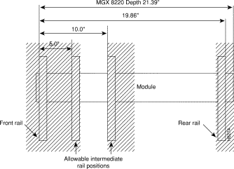
The MGX 8220 modules are designed to be mounted to two vertical rack mounting rails. A front mounting rail is used as one mounting point using the flanges provided at the front of each
MGX 8220 module. A second rail, either at the rear of the rack or at an intermediate position, is used for the second mounting point (mounting brackets are provided for attaching the module to the second rail). The allowable positions for intermediate rails is shown in Figure 6-1.
The MGX 8220 units are mounted in a specific order from the bottom to the top:
Step 2 The fan cooling assembly is mounted.
Step 3 The first shelf is mounted.
Step 4 The second shelf (if installed) is mounted.
If a third and/or fourth shelf is installed, a booster cooling assembly must be mounted immediately above the second shelf and immediately below the third and fourth shelves. The plenum or spacer unit is mounted last above the highest shelf. If a cable management kit is to used in a 2 or 4 shelf rack, the top unit must be a Plenum because cable management hardware is not supported by the Spacer unit.
When each module is installed, there should be approximately 1/32 of an inch vertical space between adjacent modules. This can be achieved by ensuring that each module is installed at the center of each standard rack increment. This space is important because it allows cards, fan and power entry modules to be removed without interference. Hardware is available in the installation kits for this purpose. (See Figure 6-5.)
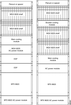
Racks with one and two shelves are shown in Figure 6-2. Racks with three and four shelves are shown in Figure 6-3.
The MGX 8220 shelf and Cooling Assembly rely on their contact with the rack for grounding. Therefore, the rack should be properly connected to earth.
The equipment should be mounted in the rack so as to prevent any hazardous condition due to uneven mechanical loading.
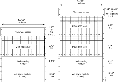
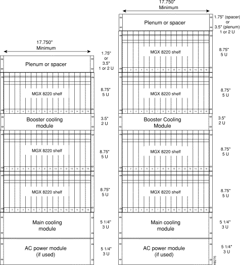
Mount the lowest module first and work upwards. In AC system, the lowest module is the AC power module, in DC systems it is the main cooling module.
Step 2 Install disposable alignment screws in upper mounting hole in the rack
Step 3 Have one person lift the first module into its position and fasten the lower front mounting screws. (See Figure 6-4.)
Step 4 Attach the angle brackets (supplied with the module), one on each side of the mounted module. Position the brackets so they can be used to secure the module to the rear rail of the rack. Holes are provided in the side of the module to accommodate various distances of the rear rail from the front rail. The angle bracket is attached to the side of the module using the provided self-tapping screws. (See Figure 6-4.) Use the disposable alignment screws on the rear positioning as well as the front to assure accurate positioning of the first unit.
Step 5 Attach the angle bracket to the rear rail in the rack using four, number 10-32 machine screws and flat washers (supplied with the module). The AC Power Module uses a special bracket at the rear that provides a small shelf for support. (See Figure 6-4). Attach the bracket to the mounting angle rack using 10-32 screws. Screws are not mandatory to hold the bracket to the module.
Step 6 Repeat Step 2 through Step 5 for the remaining modules.
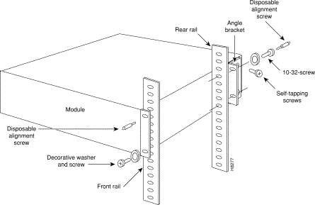
Where there is restricted depth in the rack, the holes in the side of the module can also be used to mount the shelf so the center of the module is mounted onto the front of the rack. In this arrangement, the shelf will protrude in the front of the rack and only partially protrude into the rack space.
There are several aids for mounting modules where side access is limited.
1. Use thread forming screws to prethread mounting holes. This technique involves screwing a screw into the hole to make the thread and them removing it before installing the module. The pre-threaded holes make it much easier to insert the screws when the module is installed.
2. An alternative bracket can be used for the MGX 8220 shelf rear support. This bracket locks into slots on the module chassis and does not specifically require screws in the chassis side. Ground contacts are provided for a redundant ground connection.
3. Another alternative bracket, which is part of the cable management kit, has keyhole style holes instead of the normal round holes. (See Figure 6-5.) Using this bracket, the screws can be loosely screwed into the chassis before it is installed. When the chassis is approximately in position in the rack, the bracket is then placed over the screws and slid into place. The screws are then tightened using a box end wrench from the rear. The bracket is then attached to the rack mounting rail. This bracket is used in conjunction with a spacer to ensure the 1/32" vertical space between modules. Hex head screws are provided for this purpose.
4. A additional bracket is used to properly space the main MGX 8220 chassis unit when a rear vertical mounting rail is NOT used in the assembly. Mount the cable hook on top of the bracket and use a flat washer to space the lower mounting hole.

Either the plenum chamber or the spacer unit (not both) should be mounted immediately above the shelf. The decision is dependent upon the configuration of equipment in the rack and how the air is to be expelled. The plenum delivers air to the rear of the rack and is used in normal UL compliant installations where the top of the unit must be covered. The spacer may be used for installations that may have equipment mounted above the MGX 8220 assembly that acts as the necessary top cover. The spacer guarantees the minimum necessary air exhaust space of 1.75 inches providing that the sides and rear are open and unobstructed. The MGX 8220 shelf may not be UL compliant when the spacer is used. Further, the plenum supports the attachment of a cable management kit whereas the spacer does not. This is an important factor if cable management is to be used for the upper shelf in 2 and 4 shelf configurations.
Insert the selected unit immediately above the shelf and secure to the shelf with four, number 10-32 machine screws and flat washers.
The MGX 8220 shelf is provided with a wrist strap which grounds the user and protects the electronic components from electrostatic shock. The wrist strap kit consists of a strap, a coiled cord and a clip for holding the strap. (See Figure 6-6 and Figure 6-7.)
It is recommended that the wrist strap be installed on the left front flange of one of the units at a convenient height. Use the front mounting screw to secure the ring lug to the flange and front rail. The other end of the cord is attached to the strap with a snap connector. Peel the back off the clip to expose the adhesive surface and attach to the front of the unit above the ring lug, mount the clip sideways to allow the strap to be held in a position that will not interfere with the removal of the Number 1 card. Use the clip to store the strap when not in use.


Different Cisco units, for example, the MGX 8220 shelf, the BPX switch and INS can be collocated in the same rack or cabinet. When this is done however, the inclusion and positioning of the power, cooling, booster, plenum, and spacer modules relative to the MGX 8220 shelf must be the same as when the shelf is used in a dedicated rack. Some multi-system configurations examples are shown in Figure 6-8:
In multi-system racks, the BPX switch, if included, should be mounted at the bottom. The
MGX 8220 shelves including the power, cooling, booster, plenum, and spacer should be mounted in the proper order at the top to allow for growth.
 | Warning The power to the shelf is OFF at this point. DO NOT apply power by pressing the black button until later. |
DC power is connected as described in the following steps:
Step 2 Each power entry module has a EURO Block 3-pin male power receptacle for connecting the 48VDC power sources. The mating female connector is supplied by Cisco with the power entry module.

Step 3 Attach the two supplied female EURO connectors to the two cables supplying DC power to the power entry modules. The cables should have three insulated number 12 AWG wires (solid or stranded) with the insulation stripped back 0.25" (6mm) on each wire.
Test which way the female connector attaches to the male connector using the pin assignments in Figure 6-9 as a guide. For each cable, insert each of the wires into their correct holes in the connector and secure each wire by tightening the screws in the connector.
Step 4 Connect a cable to each of the power entry module connectors. The connectors are polarized so that they cannot be inserted the wrong way.
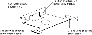
Step 5 Use the PEM cable clamp to secure the power cable. (See Figure 6-10) Place the cable clamp over the connector so the small hole is positioned over the boss on the PEM. Secure by attaching the clamp to the PEM with the captive screw. The cable clamp can be dressed to the left or right and secured to the clamp using a tie wrap.
Step 6 If the redundant PEM module is not used, the Cover Power Entry Module must be installed in the empty position to assure proper cooling of the rear cards.
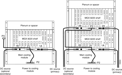
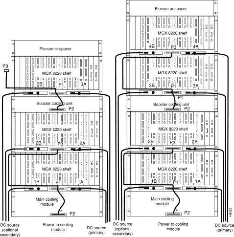
The DC cabling for single and multi-shelf racks is shown in Figure 6-11 and Figure 6-11.
1. Connect the cable to the connector on the rear of the shelf located between the power entry modules (P1 for primary and P3 for redundant). When fully inserted, the cable will latch into place preventing accidental removal. To unlatch the connector, use a small screwdriver to slide the catch lever (located inside the slot on the connector) to the right using a small screwdriver.
2. Connect the other end of the cable to the receptacle on the rear of the fan cooling assembly, P2. If the redundant portion of the cable is not used, it should be dressed to side using a cable bundle or a cable management tray.
The cooling assembly cabling for a single and multi-shelf racks is shown in Figure 6-11 and Figure 6-12.
AC Input Power
The AC power assembly can be configured with either a single primary input AC source or optional primary and secondary (redundant) input AC sources. AC power is supplied through connectors on the rear panel.
Available Power
The AC power assembly holds up to six independent 875 watt power supplies each of which supplies power to a common output bus. Power is available for the MGX 8220 shelves through connectors on the rear panel.
The number of power supplies configured in the assembly depends upon the number of MGX 8220 shelves that need to be supported. The maximum number of MGX 8220 shelves that can be supported by a single AC power assembly is four.
In a worst-case fully loaded configuration each MGX 8220 shelf requires 500 watts. Therefore, a power assembly equipped with three power supplies, totaling 2625 watts, can supply enough power for a four shelf rack. A power assembly equipped with four power supplies, totaling 3500 watts, provides enough power for a four shelf rack even in the event of a single power supply failure. More power supplies provide even more protection in the event of multiple power supply failures.
Monitoring Power Supply Status
In addition to supplying power, each power supply provides a signal that indicates the status of the power supply.
Rear Panel Connectors
The rear panel has:
Power is available at each of the four connectors on the right of the rear panel and a cable from any of these four connectors can be connected to any shelf in the rack. (See Figure 6-13.)
Each of the right three connectors of the group of four also provides a power supply status signal for monitoring power supply performance by an MGX 8220 shelf. Each of these connectors provides a status signal for a particular power supply as shown in the diagram.
The group of three connectors on the left of the rear panel supply status signals for any remaining power supplies that may be configured in the assembly.
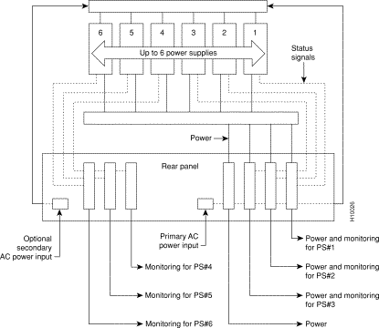
Refer to Figure 6-14 and Figure 6-15 when performing the following steps.
Step 2 The other end of the cables has a connector and a fixture for attaching to the power entry aperture on the rear of the shelf. Insert each of the two cables into one of the power entry apertures on the shelf and secure with the provided screws. The cable from the left side of the power assembly is connected to the left power entry connector in the MGX 8220 shelf. Likewise, the cable from the right side of the power assembly is connected to the right power entry connector in the MGX 8220 shelf.
Repeat steps 1 and 2 for any other shelves in the rack being powered from the same power assembly.
Step 3 The AC power source is connected to the IEC receptacle(s) on the rear of the power module. The power assembly is available in two versions:
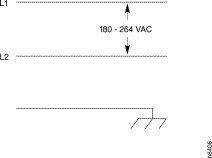
The AC power cord(s) should be plugged into a 115/240V AC, single phase, wall outlet capable of supplying 15 amps. The house circuit should be protected with a 20 amp circuit breaker.
The ground (green) wire of the AC power cord is connected to the MGX 8220 system for safety ground. Make sure that the building AC receptacle is properly grounded.
Step 4 If the left hand power connector on an MGX 8220 shelf is not used, the Cover Power Entry must be installed in the empty position to assure proper cooling of the rear cards. (See Shelf 4 in Figure 6-15.)
 | Warning The power to the shelf is OFF at this point. DO NOT apply power until later. |
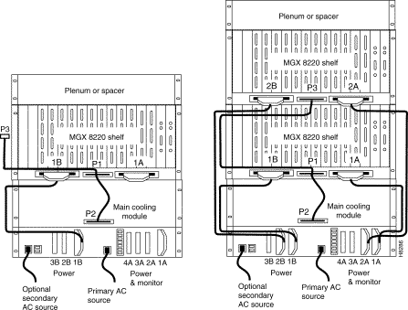
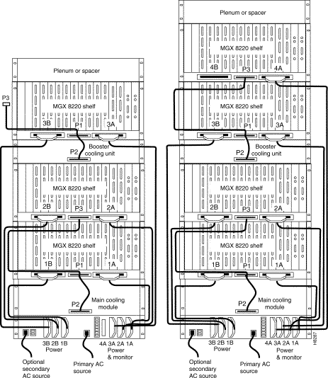
A fully loaded multi-MGX 8220 rack may have between 150 and 200 cables attached to the rack modules. Cable management kits are available for installation on the rear of rack modules. These kits provide the means to route the power and data cables in a neat and orderly fashion to and from the modules in the rack. Depending upon the number of racks in the shelf and the number of cables connected to the shelves, one or more cable management kits may be required.
The cable management kits are installed to the rear of the Cooling Module, the Booster Cooling Module and the plenum as required.
There are two basic cable management kits:
The plenum chamber kit consists of a cable management panel and the necessary brackets, screws and washers for rear mounting on the plenum. (See Table 6-1.) A cable management kit for the plenum is shown in Figure 6-16.
| Description | Quantity |
|---|---|
Number 10 flat washer | 8 |
10-32, 0.375" long screws with locking nuts | 8 |
10-32, 0.375" long thread forming screws | 4 |
Inner bracket | 2 |
Outer bracket | 2 |
Cable management panel | 1 |
Install the kit as follows:
Step 2 Install the two outer brackets onto the two inner brackets using two screws with locking nuts for each bracket.
Step 3 Install the cable management panel onto the outer brackets using two screws, locking nuts, and washers for each bracket.
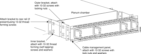
For the cable management kit that is installed on the cooling module and booster cooling module, the kit consists of a set of brackets, a power routing assembly, and the cable management panel. (See Table 6-2.) A cable management kit for the cooling and booster units is shown in Figure 6-17.
| Description | Quantity |
|---|---|
Number 10 flat washer | 12 |
10-32, 0.375" long screws with locking nuts | 8 |
10-32, 0.375" long thread forming screws | 8 |
Cable support | 2 |
Power and fan cable management assembly | 2 |
Short fan panel bracket | 2 |
Cable management panel | 1 |
Install the kit as follows:
Step 2 Install the power and fan cable management assembly onto the two short fan panel brackets using two screws with locking nuts for each bracket.
Step 3 Install the cable management panel onto the outer brackets using four screws, locking nuts, and washers for each bracket.
Step 4 Install one or both cable supports onto the MGX 8220 shelf above the cooling module using a number 10-32 thread forming screw for each support. Use two washers between the cable support on the left hand support only.
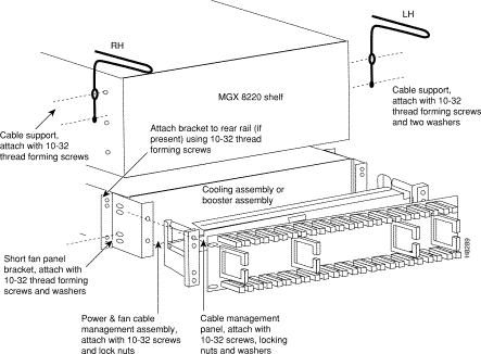
There are two kinds of power cables on an MGX 8220 shelf:
At the MGX 8220 shelf end the cables should be routed through the power cable support so they can be routed down the side of the rack as shown in Figure 6-18.

At the cooling assembly, the cable should be routed through the cable management kit. (See Figure 6-19.)
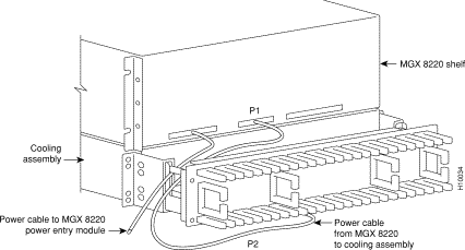
Data Cables connected to the MGX 8220 shelf back cards are routed up or down the cable management panel where they are fed through the fingers and then routed to the left or right to the side of the rack. The cables can then be routed to their appropriate equipment (router, for example).

 | Warning Before handling any cards, ground yourself by clipping the wrist strap that is supplied with the MGX 8220 shelf to a convenient metallic contact on the shelf and to your wrist. This simple procedure prevents static electrical damage to the cards. |
Systems may be shipped with empty slots with filler cards or with plug-in cards installed. If filler cards are installed in any of the slots, they may need to be replaced with functional cards. Remove, replace, and install front and back cards as necessary to obtain the correct configuration.
When seated, the MGX 8220 front cards are retained by a mechanical latch attached to the card. (See Figure 6-21.)

To remove a front card:
Step 2 Gently pull the card out of the card cage.
To install a front card:
Step 2 Gently slide the card all the way into the slot and press the insertion/extractor lever until it snaps into the vertical position.
Back cards are retained through two screws: one at the top of the faceplate and one at the bottom of the faceplate.
To remove a back card:
Step 2 Use a flat screwdriver to undo the two retaining screws in the back card's faceplate.
Step 3 Pull both of the two extractor levers out to the horizontal position, this will start the removal of the card. Gently pull the card out of the card cage.
To install a back card:
Step 2 Position the rear card guides over the appropriate slot at the top and bottom of the card cage.
Step 3 Gently slide the card all the way into the slot and tighten the two captive screws on the back card's faceplate. Tighten the upper and lower screws a small amount alternately to prevent misalignment of the card. Do not overtighten. Tighten the screws to secure the card.
 | Warning
Cards must be inserted in the correct slot positions. This is particularly true with back cards. If service module back cards are inserted into slots intended only for ASC and/or BNM back cards (slots 1, 2, 3, and 4) damage to the card and backplane can result. If you accidentally attempt to insert a service module back card into slots 1, 2, 3, or 4 and then have difficulty in operating the shelf, examine the backplane pins and the backcard connector on the wrongly inserted backcard to see if they have been bent or damaged. |
Connect two T3 coaxial cables between the T3 BNC connectors on the MGX 8220 BNM line module card and the T3 BNC connectors on the BPX BNI Line Module. The Transmit port on the BPX line module must connect to the Receive port on the MGX 8220 BNM line module and vice versa. (See Figure 6-22.)
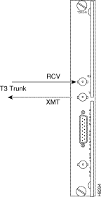
If redundant BNM cards are being used, use Y-cable adapters as shown in Figure 6-23. It is recommended that specially designed short T3 or E3 Y-cables be purchased from Cisco.
The customer's frame relay is connected to the MGX 8220 shelf through T1 or E1 lines. T1 lines use cables terminated with DB15 connectors, E1 lines use cables terminated with either DB15 or BNC connectors (depending upon the line module configuration).
Service lines using DB 15 connectors need only one cable per port. Service lines using BNC connectors require two cables (one transmit and one receive) from the E1 port of the customer's equipment to a E1 port on an MGX 8220 line module.
Dry contact relay closures are available for forwarding MGX 8220 alarms to a user office alarm system. Separate visual and audible alarm outputs are available for both major and minor alarm outputs. The MGX 8220 alarm outputs are available from a DB15 connector on the BNM line module faceplate. Refer to Appendix B, Specification, for the pinouts on this connector. Use switchboard cable for running these connections.
If the MGX 8220 node is to be synchronized to some other external equipment or a local digital central office, a connector on the back card can be used to provide a clock input.
For a T1 clock input, the DB15 connector, marked EXT TMG, on the T3E3-D line module is used.
For a E1 clock input, the BNC connector, marked EXT TMG, on the T3E3-B line module is used.
When using an alphanumeric (dumb) terminal to input Command Line Interface commands, the terminal must be connected directly (no modem) to the maintenance port DB25 connector on the ASC line module faceplate. Use a conventional RS-232 cable with a DB25 connector at each end.
A so-called "Null Modem" cable is not required. This port should never be Y-cabled.
When using a workstation to issue commands or transfer files to and from the shelf, the workstation can be attached through the RS-232 control port on the ASC line module faceplate. Using this connection requires the workstation to communicate using TCP/IP and SLIP communication protocols.
The workstation can be attached either directly with no modems or remotely through modems. In either case, a conventional RS-232 modem cable should be used.
If the shelf has dual redundant ASC modules, use a Y-cable to connect the workstation or modem to the control port of both the ASC modules. If a modem is used, a null-modem cable is required.
Before applying power to the MGX 8220 shelf, check the following items:
1. Shelf is properly grounded.
2. AC or DC power sources are properly installed and connected.
3. All cards are present in their proper slots and are locked in place.
4. T1, E1, and T3 cables are installed.
5. Control console is connected.
To apply power to a DC system, press the BLACK button on each of the power entry modules until they latch in the IN position. To apply power to an AC system, switch the circuit breakers on the rear of the power module to the ON position.
The LEDs on the front cards may flash for a few moments while the shelf performs a self-test and then settle down to Active or Standby.
When power is applied and the LEDs have stabilized:
Before the MGX 8220 shelf can receive commands, SNMP requests, file downloads, and so forth, the shelf must be assigned IP addresses for the control port, the LAN port and the in-band channel. This procedure requires a alphanumeric terminal to be connected to the maintenance port of the active ASC card and addresses assigned through the command line interface. Refer to the Cisco MGX 8220 Command Reference for details on how to login and use the specific commands.
Carry out the following procedures.
Step 2 Login to the active ASC card by typing your account, your password, and the ASCs slot number.
Step 3 Configure the IP address for each port (control, LAN and in-band) in turn using the cnfifip command. (Refer to Chapter 3, "Managing the Cisco MGX 8220 Shelf", for more details.)
The cnfifip command is entered in the format cnfifip -ip <ip address> -if <interface type> -msk <subnet mask address> -bc <broadcast address> where <ip address> specifies an IP address for the destination in dotted decimal format, <interface type> is specified as 28 for the control port and 37 for the inband port and 26 for the LAN port, <subnet mask address> and <broadcast address> specify the mask and broadcast addresses in dotted decimal format.
Step 4 While you are using the terminal, you may wish to assign a nodename for the shelf using the cnfname command.
Step 5 Logout.
Once the IP addresses have been assigned, the shelf can be managed from StrataView Plus.
![]()
![]()
![]()
![]()
![]()
![]()
![]()
![]()
Posted: Fri Jan 19 17:14:41 PST 2001
All contents are Copyright © 1992--2001 Cisco Systems, Inc. All rights reserved.
Important Notices and Privacy Statement.