|
|

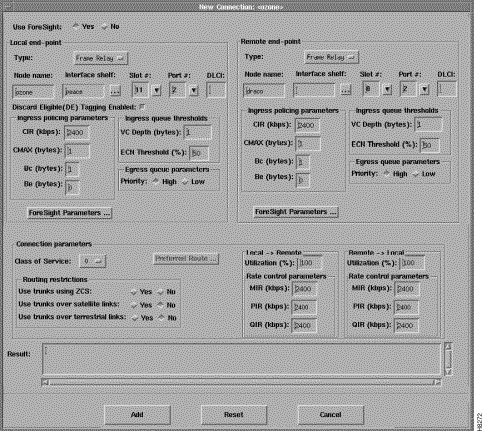
Setting up a frame relay connection is normally performed from StrataView Plus using the Connection Manager graphical user interface. An example of the StrataView Plus screen used for making an MGX 8220 shelf frame relay connection is shown in Figure 5-1. For full details of how to set up a connection, refer to the StrataView Plus User Guide.

The following paragraphs describe how to establish an end-to-end frame relay connection assuming network interworking and the MGX 8220 FRSM end points.
Figure 5-2 shows two BPX nodes in a BPX network in which each of these two nodes is connected to an MGX 8220 shelf via an BNI card. User frame relay equipment, located at "A", is attached to one of the MGX 8220 shelves via a port on the shelf's FRSM card. Likewise, user frame relay equipment, located at "B", is attached to the other MGX 8220 shelf. This chapter describes how a frame relay connection can to be established to permit bidirectional communication between the frame relay equipment at "A" and "B".

In order to make the connection, the path from "A" to "B" is made up of three segments as shown in Figure 5-2. When using CLI, each segment must be established and configured separately.
Two segments span from the FRSM to the BNM on the MGX 8220 shelves. These segments are part ATM and part frame relay with the conversion being made in the MGX 8220 shelves.
There is also an ATM trunk segment that spans the BPX backbone network from one of the BPX nodes to the other BPX node, this segment terminates on a BNI feeder trunk in each node. This segment may include intermediary BPX nodes (not shown in the diagram).
The links between the segments must be configured properly so the three segments make up one complete end to end connection from "A" to "B". This process consists primarily of ensuring that the VPI between the MGX 8220 shelf and the collocated BPX switch contain the MGX 8220 slot number of the FRSM and the VCI contains the logical channel numbers assigned to the virtual circuit.
To establish an end to end frame relay connection, establish the customer equipment to BPX Segments. This must be performed on the MGX 8220 shelf at BOTH ends of the connection
("A" and "B").
On the MGX 8220 shelf:
Step 2 If not already enabled, enable the T1 line to be used for the frame relay connection by performing an addln command using the physical FRSM connector number (1 to 4) connected to the T1 line.
Step 3 If not already configured, configure the T1 line to the frame relay equipment using the cnfln command. Specify parameters as appropriate.
Step 4 If not already enabled, enable the port to the frame relay equipment by performing an addport command using the parameters as follows:
Step 5 Enable the frame relay channel by performing an addchan command.
At this point the MGX 8220 segment is up with default parameters.
1. Perform an addcon command at one of the BPX nodes (not both) with the following parameters.
2. Specify the other addcon parameters of bandwidth, and so forth.
| Parameter | Description |
|---|---|
MCR | Minimum Cell Rate |
PCR | Peak Cell Rate |
% Util | Percentage utilization of channel |
Minimum Cell Rate (MCR) is only used with ForeSight (ATFST).
MCR and Peak Cell Rate (PCR) should be specified according to the following formulas:
MCR = CIR *3/800 cells per second
PCR =AR * 3/800 cells per second but less than or equal to 6000.
Where AR = Frame relay port speed in bps
For example: | AR equals 64K, PCR = 237, or |
The above MCR and PCR formulae assume a fairly pessimistic frame size of 100 octects, however, even smaller frame sizes can result in worse case scenarios. For example:
For a frame size of 64 octects the PCR formula becomes | PCR = AR * 2/512 cells per sec |
For a frame size of 43 octects the PCR formula becomes | PCR = AR * 2/344 cells per sec |
% Util should normally be set to the same value as that used for the frame relay segments of the connection.
FRSM service interworking connections are made in the same manner as the network interworking connections except that chan_type in the MGX 8220 shelf addchan command is specified as service interworking (transparent or translation) and the connection end that is remote from the MGX 8220 shelf is an ATM UNI.
These services are setup the same as frame relay except the for port_type in the addchan command which is set as 2 for FUNI or 3 for frame forwarding.
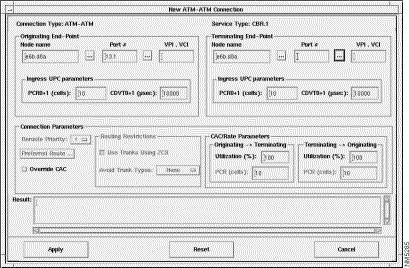
Setting up an AUSM connection is normally performed from StrataView Plus using the Connection Manager graphical user interface. An example of the StrataView Plus screen used for making an MGX 8220 shelf ATM to ATM connection is shown in Figure 5-3. For full details of how to set up a connection, refer to the StrataView Plus User's Guide.

Use the following sequence of commands to establish an ATM UNI/NNI connection using the AUSM card. The connection is between a T1 or E1 ATM UNI on the AUSM card and an ATM service interface elsewhere in the IPX/BPX network.
1. Login to AUSM.
2. Issue addln command specifying the line/port number (between 1 and 4), 1 being the top line/port.
3. If required, use cnfln command specifying line code, line length, and clock source.
4. Issue upport command specifying the port to be upped.
5. Use cnfportq to setup egress queues. Other than defaults you need to specify:
port number (1-4)
queue number (1-16)
queue priority
0 = disable queue
1 = high priority, always serve
2 = best available
3 = Min. guaranteed bandwidth
4 = Min. guaranteed bandwidth with max. rate shaping
5 =CBR with smoothing
service sequence number (1-16)
max. queue depth (1-8000)
CLP low threshold (1-8000)
CLP high threshold (1-8000)
EFCI threshold (1-8000)
6. Use addcon command to add the connection, specifying:
logical connection (LCN 16-271)
connection type (1 = vpc, 2 = vcc)
port number (1-4)
vpi (0-255)
vci (0-65535)
service type (1 = cbr, 2 = vbr, 3 = abr)
queue number (1-16)
7. For configuring UPC, use one of
cnfupc cbr
cnfupc vbr
cnfupc abr
8. Use cnfchanfst to configure ForeSight
9. If queue depths need to be changed, use cnfchanq command
For the BPX segment, set up the connection in the same manner as that for FRSM. The connection type should be specified as ABR, CBR, or VBR to match the connection type used at the connection endpoint (for example, AUSM). The parameter values map directly from those specified at the connection endpoint.
![]()
![]()
![]()
![]()
![]()
![]()
![]()
![]()
Posted: Fri Jan 19 17:13:24 PST 2001
All contents are Copyright © 1992--2001 Cisco Systems, Inc. All rights reserved.
Important Notices and Privacy Statement.