|
|

In Release 3.0, the MGX 8220 shelf offers the following types of service modules:
Up to a total of 10 service modules can be configured in the MGX 8220 shelf in slots 5 through 14.
Current service modules (T1/E1 service modules) can be configured with 1:N redundancy protection if an optional SRM card is installed. For redundancy of a group of like service modules, a single spare service module (of identical type and version) is installed in slot 12, 13, or 14. Up to three groups (three types of service module) can be protected in this way.
The MGX 8220 shelf Release 3.0 offers the Inverse Multiplexing for ATM Trunk Module (IMATM) with support for 1:1 redundancy (no SRM required).
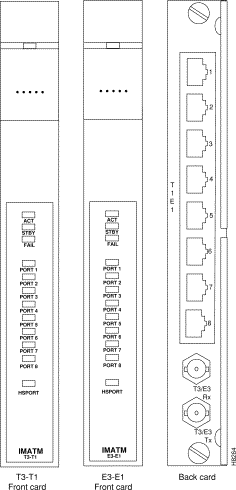
The IMATM is a two-card set consisting of a function module front card and a line module back card. (See Figure 4-1.)

The following front card and line module sets are available:
| Front Card: IMATM-T3-T1 Back Card: RJ48-T3T1T1 Line |
Miniature RJ-48C |
| Front Card: IMATM-E3-E1 Back Card: RJ48-E3E1 |
Miniature RJ-48C |
| Front Card: IMATM-E3-E1 Back Card: SMB-E3E1 |
Miniature SMB |
The shelf may contain one or multiple IMATM card sets in any available service module slot.
1:1 IMATM redundancy is achieved by installing two card sets and a Y-cable.
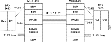
The IMATM performs no MGX 8220 shelf functions and is solely an extension to the BPX BNI card. The BPX switch can use up to 8 T1 or E1 lines as a trunk (instead of a single T3 or E3 line) by using an IMATM card in the MGX 8220 shelf.
The IMATM accepts trunk signals from the BPX BNI over a single T3 or E3 connection and inverse multiplexes them over multiple T1 or E1 lines. The other end of the inversed multiplexed trunk is another IMATM card in a remote MGX 8220 shelf. (See Figure 4-2.)

The IMATM can also be used to connect a remote the MGX 8220 shelf to a BPX hub.
(See Figure 4-3.)

Up to eight T1 or E1 links in the inverse multiplexed channel can be configured depending upon the bandwidth desired. Bandwidth of T1 links range from 1.54 Mbps for one link to 12.35 Mbps for all 8 links. Bandwidth of E1 links range from 2 Mbps for one link to 16 Mbps for all 8 links. The BNI port bandwidth is configured to match the IMATM bandwidth.
Additional links can be provisioned to provide some protection against link failure. To achieve this, the BNI trunk should be programmed to have a statistical reserve equal to the bandwidth of the extra links. In the event of a link failure, a minor alarm occurs but no rerouting. Without this feature, a single link failure will cause a major alarm and all connections will be rerouted over another trunk.
The IMATM has the following LED indicators, all located on the faceplate of the front card.
ACTIVE (ACT) LED Green:
STANDBY (STBY) LED Yellow:
FAIL (FAIL) LED Red:
Port (PORT) LED Green, Red or Yellow, one LED per line:
High Speed Port (HSPORT) Green, Red of Yellow
The Frame Service Module (FRSM) is a two-card set consisting of an FRSM front card (channelized or fractional, T1 or E1) and either a 4 T1 or a 4 E1 back card. Up to 10 FRSMs may be installed in a shelf in slots 5 through 14. A FRSM Front Card is shown in Figure 4-4.

Fractional FRSMs support one 56 kbps or one Nx64 kbps customer port (FR-UNI, FR-NNI, ATM-FUNI, and Frame Forwarding) per T1/E1 line. Channelized FRSMs support multiple 56 kbps or Nx64 kbps customer ports per T1/E1 line, up to the physical line's bandwidth limitations.
The FRSM supports up to a maximum of 256 connections (virtual circuits) which can be allocated across the 4 T1 or E1 lines in any manner. The maximum frame size is 4510 bytes for frame relay and 4096 for ATM-FUNI.
The main function of the FRSM cards is to perform the necessary conversions between the frame formatted data on its 4 T1 or E1 lines and ATM/AAL5 cell formatted data received and transmitted over the Cell Bus. The FRSM performs the frame to cell segmentation and reassembly and the address translation between frame relay port/DLCIs, FUNI port/frame address, or Frame Forwarding port, and the ATM virtual connection identifiers (VPI/VCIs).
For frame relay, the FRSM can be configured to perform network interworking or service interworking. Network interworking and Service interworking connections can be freely intermixed on the same FRSM and the same physical port of the FRSM. The type of interworking is specified on a PVC by PVC basis.
Using the MGX 8220 shelf, FR-ATM network interworking permits a permanent virtual connection to be established between two frame relay service users over a WAN switching network or multi-vendor network. Across the network the traffic is carried in ATM cells.
By specifying "network interworking" as the channel type when adding a frame relay PVC to an FRSM, all PVC data is subject to network interworking translation and mapping.
Figure 4-5 shows a BPX network with network interworking connections.

In addition to frame to cell and DLCI to VPI/VCI conversion, the network interworking feature maps cell loss priority (CLP) and congestion information between frame relay and the intermediate ATM formats.
Each Frame Relay/ATM network interworking connection can be configured as one of the following DE to CLP mapping schemes:
Each Frame Relay/ATM network interworking connection can be configured as one of the following CLP to DE mapping schemes:
If the EFCI field in the last ATM cell of a segmented frame received is set, then FECN of the frame relay frame will be set.
The management of ATM layer and FR PVC Status Management can operate independently. The PVC status from the ATM layer will be used when determining the status of the FR PVCs. However, no direct actions of mapping LMI A bit to OAM AIS will be performed.
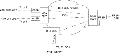
By specifying "service interworking" as the channel type when adding a frame relay PVC to an FRSM, all PVC data is subject to service interworking translation and mapping in both the frame relay to ATM and ATM to frame relay directions.
Figure 4-6 shows a BPX network with service interworking connections.

The diagram shows the MGX 8220 shelf unit and an FRSM to the right with three frame relay connection endpoints. These connections indicate the frame relay ends of service interworking connections. The diagram shows some possibilities for terminating the other ends of the connections:
In addition to frame to cell and DLCI to VPI/VCI conversion, the service interworking feature maps cell loss priority and congestion information between the frame relay and ATM formats. The service interworking is full Frame Relay Forum (FRF.8) compliant and provides full support for routed and bridged PDUs, transparent and translation modes, and VP translation.
Each frame relay to ATM service interworking connection can be configured as one of the following Discard Eligibility (DE) to Cell Loss Priority (CLP) schemes:
Each frame relay to ATM service interworking connection can be configured as one of the following CLP to DE mapping schemes:
Setting up the cell loss priority option is accomplished through the MGX 8220 shelf configure channel map cnfchanmap command.
Each frame relay to ATM service interworking connection can be configured as one of the following Forward Explicit Congestion Notification (FECN) to Explicit Forward Congestion Indicator (EFCI) schemes:
Frame relay to ATM service interworking connections use the following EFCI to FECN/BECN mapping schemes:
Setting up the congestion indication option is accomplished through the configure channel map cnfchanmap command.
The FRSM maps the C/R bit of the received frame relay frame to the CPCS-UU least significant bit of the AAL 5 CPCS PDU.
The least significant bit of the CPCS-UU is mapped to the C/R bit of the frame relay frame.
Service Interworking can operate in either Translation or Transparent mode on a per connection basis. In translation mode the FRSM performs protocol translation between the FR NLPID encapsulation (RFC 1490) and the ATM LCC encapsulation (RFC 1483). In transparent mode, no such translation takes place. Service Interworking also supports address resolution by transforming Address Resolution Protocol (ARP, RFC 826) and Inverse ARP (inARP, RFC 1293) between their Frame Relay and ATM formats when the PVC is configured as Translation Mode.
The FRSM card can be configured as "Frame Forwarding" on a port by port basis.
When frame forwarding, the operation is the same as that for frame relay except:
The FRSM support the ATM Frame User to Network Interface (FUNI). Upon receiving a frame from the FUNI interface, the 2 byte FUNI header is removed and the frame is processed into ATM cells using AAL-5 for transmission over the network. In the reverse direction ATM cells are reassembled into frames using AAL-5, the FUNI header is added and the frame is sent to the FUNI port.
The CLP bit on the FUNI header is mapped to the CLP bit of every ATM cell that is generated for the FUNI frame.
CLP bit in the FUNI header is always set to 0.
EFCI is set to 0 for every ATM cell generated by the segmentation process.
If the EFCI field in the last ATM cell of a received segmented frame is set to 1, the CN bit in the FUNI header is set to 1. The two reserve bits (the same positions as C/R and BECN in Frame Relay header) are always set to 0.
The ATM UNI Service Module (AUSM) is a two-card set consisting of an AUSM function module front card and either a 4 T1 or a 4 E1 line module back card. The E1 line module cards are further categorized by BNC or DB15 connector type.
Up to 10 AUSMs may be installed in a shelf in slots 5 through 14.
The main function of the AUSM cards is to provide an ATM UNI/NNI interface at T1 or E1 rates so that ATM UNI user devices can transmit and receive traffic over an ATM BPX network.
The AUSM supports up to a maximum of 256 connections which can be allocated across the 4 T1 or E1 lines in any manner, the connections can be either VPC or VCC as follows:
The BNM performs the appropriate header translation and routes cells to the correct slot.
The AUSM has extensive traffic control features. The ForeSight feature provides virtual circuit and virtual path end-to-end flow control support.
The AUSM contains 8000 cell queue buffers for each ingress and egress data flow. The Usage Parameter Control (UPC) algorithm and the queues are user configurable.
CAC is implemented to support separate% utilization factors, PCRs, and MCRs for both ingress and egress CLI.
An illustration of the AUSM card set is provided in Figure 4-7.

The AUSM has the following LED indicators, all located on the faceplate of the front card.
PORT LED Green, Red or Yellow:
ACTIVE LED Green:
STANDBY LED Yellow:
FAIL LED Red:
The Circuit Emulation Service Module (CESM) is a two-card set consisting of an CESM function module front card and either a 4 T1 or a 4 E1 line module back card. The E1 line module cards are further categorized by BNC or DB15 connector type. The three possible line modules are:
Up to 10 CESMs may be installed in a shelf in slots 5 through 14. 1:N redundancy is supported through the SRM-T1E1 board.
The main function of the CESM cards is to provide a constant bit rate (CBR) service for T1/E1 ports over ATM BPX network.
The CESM converts DS1/E1 data streams into CBR AAL1 cells for transport across the ATM network.
The CESM card supports either 4 T1 or 4 E1 ports. Each T1 or E1 port supports a single synchronous unstructured data stream with a data rate of 1.544 Mbps or T1 and 2.048 Mbps for E1. Data rates are not configurable. A single CESM card supports, therefore, up to four connections.
An illustration of the CESM card is provided in Figure 4-8.

The CESM has the following LED indicators, all located on the faceplate of the front card.
PORT LED Green, Red or Yellow:
ACTIVE LED Green:
STANDBY LED Yellow:
FAIL LED Red:
Release 3.0 of the MGX 8220 shelf provides back cards for service modules that connect to 4 T1 and 4 E1 lines. The E1 back cards are further categorized by BNC or DB15 connector type. The three possible back cards are:
The back cards provide the physical line connections to either the T1 or E1 lines and communicate with their front cards through the MGX 8220 shelf backplane. A front card/back card set are always installed in the same slot position.
When the SRM is used to provide 1:N redundancy for T1/E1 service modules, the standby (redundant) card set uses a special redundancy backcard. (See Figure 4-9.) There are three types of redundancy backcards; R-DB15-4T1, R-DB15-4E1, and R-BNC-4E1 depending upon the line type (T1 or E1) and the E1 connector type (DB-15 or BNC). When 1:N redundancy is invoked, the physical lines to failed service module backcard are still used but the signals are routed to and from the redundancy backcard.

![]()
![]()
![]()
![]()
![]()
![]()
![]()
![]()
Posted: Fri Jan 19 17:11:56 PST 2001
All contents are Copyright © 1992--2001 Cisco Systems, Inc. All rights reserved.
Important Notices and Privacy Statement.