|
|

This chapter describes the hardware and functionality of the processor and trunk cards. It also describes the backplane and system bus. The description of each card includes:
For all matters relating to installation, troubleshooting, user-commands, and repair and replacement, refer to the IGX Installation Manual.
Other manuals that relate to IGX operation are:
Table 3-1 lists the front processor and trunk cards that can operate in the IGX. Table 3-2 lists the corresponding back cards. In addition, the IGX may use Adapter Card Modules (ACMs) to connect existing IPX 16/32 service modules and perform the adaptation that allows IPX 16/32 front cards to operate in an IGX 8, 16, or 32. (IPX 8-specific cards do not apply to the upgrade scheme.)
| Card Acronym | Card Name | Model |
|---|---|---|
NPM-32 | Nodal Processor Module with 32 Mbytes DRAM | B |
NPM-64 | Nodal Processor Module with 64 Mbytes DRAM | C |
NPM-64B | Nodal Processor Module with 64 Mbytes DRAM | F |
NTM | Network Trunk Module with ACM | E |
NTM | Network Trunk Module, single card — no ACM | F |
BTM | Broadband Trunk Module | A |
ALM/B | ATM Line Module, Model B | A |
| Card Acronym | Card Name | Model |
|---|---|---|
SCM | System Clock Module | C |
AIT-E3 | E3 Trunk Interface Card | A |
AIT-E2 | E2 Trunk Interface Card | A |
AIT-HSSI | HSSI Trunk Interface Card | A |
AIT-T3 | T3 Trunk Interface Card | A |
BC-UAI-1T3 | Universal ATM Interface T3 Back Card | A |
BC-UAI-1E3 | Universal ATM Interface E3 Back Card | A |
BC-E1 | E1 Interface Card | A |
BC-T1 | T1 Interface Card | A |
BC-Y1 | Y1 Trunk Interface Card | A |
BC-J1 | J1 User (Circuit) Interface Card | A |
BC-SR | Subrate Trunk Interface Card | A |
Front cards and back cards have faceplates with indicator LEDs and, on some front cards, push-button controls. In addition, back card faceplates have the cable connectors. In slots where no back card exists, a blank faceplate must reside to contain Electromagnetic Interference (EMI) and Radio Frequency Interference (RFI) and to ensure correct air flow.
The LED indicators are on the front and back card faceplates. Each plug-in card has both a green ACTIVE LED and a red FAIL LED at the bottom of the faceplate. In general, the meaning of each LED is indicated in Table 3-3. Some other cards have additional indicators, connectors, or controls, which the appropriate sections describe.
| Indicators | Status | Meaning |
|---|---|---|
FAIL | ON Steady | Indicates an error occurred. Resetting the card with the resetcd f command is suggested first. If the LED comes on again, call Customer Service. |
FAIL | Blinking | On an NPM in a redundant system, this combination indicates that the card is being updated. |
ACTIVE | ON steady | When steadily on, this combination indicates the card is active and carrying traffic or processing data. |
ACTIVE | ON momentarily | When momentarily on, indicates the card executed a self-test. |
BOTH | OFF | Indicates the card part of a redundant pair and is in the standby mode or not being used at all. |
BOTH | ON | Indicates the card failed but remains active because no standby card is available. In the case of an HDM or LDM card, this could indicate that one or more of the data channels failed, but the others are still active. |
The processor card group consists of the Nodal Processor Module (NPM) and the System Clock Module (SCM). In conjunction with the system bus, the processor group is responsible for system timing, network control, and status reporting.
The Nodal Processor Module (NPM) is a microprocessor-based system controller that runs the software for controlling the IGX. The NPM communicates with the other system cards over the control bus. Figure 3-1 illustrates the relation of the NPM to other parts of the system. The NPM performs the following major functions:
The NPM communicates with all other nodes through a trunk that uses a reserved data link at about 600 packets per second (pps). The NPM communication link with other nodes carries information about new connections, topology changes, and rerouting.
One version of the NPM-32 and two versions of the NPM-64 exist. These three NPMs are the NPM-32, NPM-64, and NPM-64B. In addition, the B versions use +5 VDC flash memory. Both versions of the NPM can reside in the same node if the resident software version supports the NPM-B version. The next section, titled "NPM Processor and Memory Capacity ," describes NPM memory and its expandability.
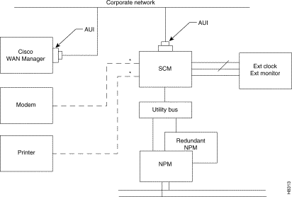
The DRAM memory in an NPM holds the switch software for performing the regular functions of the NPM. The NPMs also have memory features that let you download new software releases over the network and maintain the system software and its configuration if the power fails. Non-volatile flash EEPROM supports software downloading over the network. Battery-backup RAM (BRAM) stores system configuration data. Table 3-4 shows the basic memory capacities of each NPM.
| NPM Version | DRAM | BRAM | Flash EEPROM |
|---|---|---|---|
NPM-32 | 32 Mbytes | 1 Mbyte | 4 Mbytes |
NPM-64 | 64 Mbytes | 1 Mbyte | 4 Mbytes |
NPM-64-B | 64 Mbytes | 1 Mbyte | 4 Mbytes |
An IGX has one NPM in a non-redundant system or two NPMs in a redundant system. In a non-redundant system, an NPM resides in either front slot 1 or front slot 2. For a redundant system, NPMs reside in slots 1 and 2. The NPM plugs into the system bus backplane. A utility bus in the backplane connects the NPMs in a redundant system.
The faceplate of the NPM has a green ACTIVE LED and a red FAIL LED. See Figure 3-2 . The NPM monitors its own activity and, if a failure is detected, the FAIL LED is lit. If the node has redundant NPMs, the on-line NPM is indicated by the lit ACTIVE LED, while the standby NPM has no lit indicators. In addition to the status LEDs on the NPM faceplate, information on any NPM can be displayed at a terminal by executing the dspcd command.
 NPM Faceplate
The SCM plugs into back card slot 1. The NPM and SCM card set are the backbone of the IGX system. The NPM controls and monitors the SCM control buses. A single SCM can support redundant NPMs.
In addition, the SCM provides:
The SCM circuits include of the following:
The two serial RS-232 ports provide connection to network management terminals and modems for remote access to the node. In conjunction with the SCM, the NPM also supports a high-speed Ethernet LAN port for faster system statistics transfer between the node and a StrataView Plus NMS workstation. This port conforms to the requirements of IEEE standard 802.3 for Ethernet.
The SCM has duplicates of the internal clock circuitry and its associated phase lock loops and NPM-related control circuitry. One operates off the System A Bus, and the other operates off the System B Bus. Both circuits are independent and are monitored separately to provide complete backup if a circuit fails (FAIL lamp comes on). However, since both the System A bus and System B bus clock circuits exist on a single card, removing the SCM disrupts system operation. The lower priority SCM circuits are not duplicated. The lower priority circuits are the external clock input, control and auxiliary ports, and monitoring circuits for power supplies, cabinet temperature, and fans. A failure in a lower priority circuit does not cause a system failure, but the SCM reports the problem.
The Ext Clock connector on the faceplate of the SCM provides an interface for an external source for a high-stability clock. This clock is configurable as the primary, secondary, or tertiary clock. The input is 1.544 MHz for T1 systems and 2.048 MHz for CEPT systems. In addition, one of the trunk or circuit line inputs may also serve as a source of timing for the node. If no clock source is selected, the clock source is the internal IGX clock.
Refer to Figure 3-3 and Table 3-5 for details on the SCM faceplate. When you correlate the descriptions in the table with the callouts in the figure, read from the top to the bottom.
In addition to the clock functions, the SCM provides a pair of low-speed, serial communications ports. The CONTROL TERMINAL port is a bi-directional port for connecting the IGX to a local network control terminal or to a modem for remote terminal connection. The AUXILIARY PORT connects to a maintenance log printer, an additional dumb terminal, an alarm message collector, external device window, or an auto-dial modem for automatic reporting of local IGX alarm conditions. You can program the modem can to dial into Customer Service for assistance when a network alarm occurs.
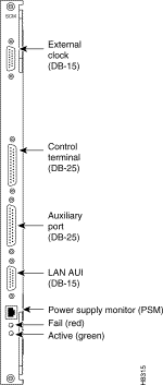
EXTERNAL CLOCK | DB15 connector for connecting an external source for the system clock. |
CONTROL TERMINAL | A DB25 connector for a VT100 or equivalent terminal for a basic network management terminal. It can also be connected to a dial-in modem for ISC or other network management dial-up access. This is a bidirectional RS232 communications port. |
AUXILIARY PORT | A DB25 connector for a system printer. Can also be used to connect to an out-dial modem or automatic reporting of alarms in the event the node becomes isolated. This is a bidirectional RS232 port. |
LAN AUI | Ethernet LAN connection for multiple, local StrataView Plus NMSs. This port uses a DB-15 connector called the Attachment Unit Interface (AUI) connector. This name reflects the industry standard term for a LAN interface. Table 3-6 lists the AUI pin assignments. |
PSM | Power supply monitor, cable supplied by customer. |
FAIL | Indicates an error occurred. Resetting the card with the resetcd f command is suggested first. If the LED comes on again, call the StrataCom ISC. |
ACTIVE | Indicates the card is in service with active circuits. |
Table 3-6 lists the pin assignments for the LAN connector.
| Pin | Name | Pin # | Name |
|---|---|---|---|
1 | Shield | - | - |
2 | Collision Presence + | 9 | Collision Presence— |
3 | XMT + | 10 | XMT— |
4 | Reserved | 11 | Reserved |
5 | RCV + | 12 | RCV— |
6 | Power return | 13 | Power (+12V) |
7 | Reserved | 14 | Reserved |
8 | Reserved | 15 | Reserved |
StrataCom can upgrade IPX service/interface cards for use in an IGX. This allows the IGX to provide all the services of the IPX with cards of proven efficiency, functionality, and reliability. The upgrade is available only as a factory upgrade. The factory upgrade consists of an adding one of three possible Adapter Card Modules (ACM) and possible firmware or hardware modifications. Due to the complexity of the ACM, field upgrades of IPX cards are not possible.
Connecting IPX front cards to their corresponding back cards on the IPX requires the use of a utility or local bus. On upgraded IPX cards (IGX cards), the local or utility bus is not necessary.
The following IPX cards can be adapted for use in the IGX:
The IGX supports the following types of trunk cards:
The NTM works with the following back cards:
The BTM works with the following back cards:
The ALM/B works with the following back cards:

Trunk cards require no maintenance except for replacement after a confirmed failure. The tstcon command does not work on an AIT, BTM, or ALM/B because the card cannot be isolated from the BPX or other connecting ATM trunk.
A trunk loopback test runs when an ATM trunk detects an integrated alarm. The loopback test indicates if the line or the card is faulty. A loopback test "pass" means the line is faulty, and a line alarm is indicated. A loopback test "fail" means the card is faulty. If the card is faulty, a switch occurs to an available Y-Cable equipped redundant card.
The Network Trunk Module (NTM) manages FastPacket transmission across a trunk line. NTM functions include the following:
An NTM can occupy any available front slot in the range 3 to 8. The choice of back card depends on the trunk interface type. All the service card slots may hold NTMs.
For fractional T1 trunk lines, the NTM and BC-T1 card set can provide the interface. Fractional trunk interfaces use a group of 64-Kbps channels, which constitute a partial T1 trunk. For example, a 512-Kbps fractional T1 trunk might use every third channel from 1 through 24. Fractional trunks use the basic trunk frequency (such as 1.544 Mbps for T1) for the clock rate. The network operator makes the channel assignments.
Fractional E1 is the same as fractional T1 except that the channels are 1 to 15 and 17 to 31 (0 and 16 reserved) and the clock rate is 2.048 Mbps).
The NTM supports subrate trunks if a BC-SR back card and appropriate local bus are present. Subrate trunks interface to the digital transmission facility at trunk rates in the range 256 Kbps through 2.048 Mbps. Three interface connections are provided. These are RS449, X.21, and V.35.
The NTM can be configured for 1:1 redundancy by using a second, identical, card group and a Y-cable for connection to the trunk. All of the back cards support redundancy.
The faceplate of the NTM has four LEDs. The first two in the following list apply to the NTM front card. Each of the other two LEDs is a summary alarm for the back card conditions. When lit, these LEDs have the following significance:
For more information on the significance of alarm LEDs, see the IGX Installation Manual.
The alarms and line conditions that the NTM monitors include those in the following list. To view packet line errors, use the dspplnerrs command. To see a list of the user-specified packet line errors that the display can show, use dspplnstatcnf.
The T1 Trunk Interface Card (BC-T1) card terminates a single 1.544 Mbps T1 trunk line on the NTM. The BC-T1 can reside in any rear slot 3-8 in an IGX 8, 3-16 of the IGX 16, or 3-32 of the IGX 32. The BC-T1 connects directly to the NTM.
The BC-T1 provides the following:
B8ZS supports clear channel operation because B8ZS eliminates the possibility of a long string of 0s. B8ZS is preferable whenever available, especially on trunks.
The BC-T1 supports two clock modes. The clock modes are normal clocking and loop timing. You select the mode through software control. With normal clocking, the node uses the receive clock from the network for the incoming data and supplies the transmit clock for outgoing data. The node can use the receive clock to synchronize itself with the network.
With loop timing, the node uses the receive clock from the network for the incoming data and redirects this receive clock to time the transmit data.
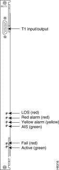
Figure 3-4 and Table 3-7 provide information on the faceplate of the BC-T1. When you correlate the descriptions in the table with the callouts in the figure, read from the top of the table to the bottom. The standard port connector is a female DB15.
| Connector/Indicator | Function |
|---|---|
T1 INPUT/OUTPUT | Female DB15 connector for T1 line. |
LOS light (red) | Indicates loss of signal at the local end. |
Red alarm light (red) | Indicates loss of local E1 frame alignment, or it indicates loss of packet alignment on the NTM. |
Yellow alarm light (yellow) | Indicates loss of frame alignment at remote end or loss of packet alignment (NTM). |
AIS light (green) | Indicates the presence of all ones on the line. |
FAIL light (red) | Indicates an error occurred. Resetting the card with the resetcd f command is suggested first. If the LED comes on again, call Customer Service. |
ACTIVE: light (green) | Indicates the card is in service with active circuits. |
The E1 Trunk Interface Card (BC-E1) provides an E1 trunk interface for the Network Trunk Module (NTM). The BC-E1 connects directly to the NTM and can reside in any rear slot 3-8 in an IGX 8, 3-16 in an IGX 16, or 3-32 in an IGX 32. The BC-E1 provides the following:
The BC-E1 supports two clock modes. The clock modes are normal clocking and loop timing. You select the mode through software control. With normal clocking, the node uses the receive clock from the network for the incoming data and supplies the transmit clock for outgoing data. The node can use the receive clock to synchronize itself with the network.
With loop timing, the node uses the receive clock from the network for the incoming data and redirects this receive clock to time the transmit data.
Statistics are kept on most line errors and fault conditions, including the following:
Figure 3-5 shows and Table 3-8 lists status LEDs and connections on the BC-E1 faceplate. When you correlate the table and figure items, read from the top to the bottom.

Connector/Indicator | Function |
|---|---|
RX-TX | Female DB15 connector for XMT and RCV E1. |
RX | BNC connector for receive E1 line. |
TX | BNC connector for transmit E1 line. |
LOS light (red) | Indicates loss of signal at the local end. |
Red alarm light (red) | Indicates loss of local E1 frame alignment. On an NTM, Red alarm indicates loss of packet alignment. |
Yellow alarm light (yellow) | Indicates loss of frame alignment at remote end. On an NTM, Yellow alarm indicates loss of packet alignment. |
AIS light (green) | Indicates the presence of all ones on the line. |
MFRA light (red) | Indicates loss of multiframe alignment (E1 only). |
MFRY light (yellow) | Indicates loss of multiframe at remote end (E1 only). |
FAIL light (red) | Indicates an error occurred. Resetting the card with the resetcd f command is suggested first. If the LED comes on again, StrataCom call the ISC. |
ACTIVE: light (green) | Indicates the card is in service with active circuits. |
The Back Card/Subrate (BC-SR) terminates subrate trunks on the NTM. A subrate trunk uses part of the E1 or T1 bandwidth. The BC-SR typically functions in tail circuits or where little traffic exists.
A subrate trunk facility interface operates in DCE mode, and the subrate channel functions like a synchronous data channel. Therefore, the IGX BC-SR always operates in DTE mode. Only leased lines are supported (no dial-up lines). Subrate trunks cannot pass clock signals between nodes.The BC-SR provides the following:
Figure 3-6 and Table 3-9 describe the BC-SR faceplate. When you correlate the figure and table, read from the top down.
Table 3-10 lists the data signals and EIA leads supported by the subrate interface.
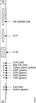
RS-449 data connector | DB37 female connector |
X.21 data connector | DB15 female connector. |
V.35 data connector | 34-pin female MRAC connector |
LOS light (red) | Loss of signal at the local end. |
Bad CLK light (red) | Loss of clock or clock out of range |
Yellow alarm light (yellow) | Loss of packet alignment (NTM) or frame alignment at remote end |
DSR light (green) | The DSR lead is high (ON) |
DTR light (green) | The DTR lead is high (ON) |
RXD light (green) | The receive data line shows activity |
TXD light (green) | The transmit data line shows activity. |
FAIL light (red) | An error occurred. (First, reset the card with resetcd f. If the LED comes on again, call Customer Service.) |
ACTIVE: light (green) | The card is in service and has active circuits. |
| Transmit | Receive | ||||
|---|---|---|---|---|---|
| Lead | Name | Interface | Lead | Name | Interface |
TX | Transmit data | All | RX | Receive data | All |
RTS | Request to Send | V.35 | CTS | Clear to Send | V.35 |
DTR/C | Data Terminal Ready | All | DSR/I | Data Set Ready | All |
LL | Local Loop | RS422 | DCD | Data carrier select | V.35 |
RL | Remote Loop | RS422 | RI/IC | Ring Incoming Call | V.35 |
IS | Terminal In Service | RS422 | TM | Test mode | V.35 |
SS | Select standby | V.35 | SB | Standby indicator |
|
SF | Sig rate select |
| SI | Signalling rate |
|
The BC-Y1 back card provides a Japanese Y1 trunk interface for an NTM. The BC-Y1 can reside in any rear slot 3-8 in an IGX 8, 3-16 in an IGX 16, or 3-32 in an IGX 32. The BC-Y1 provides:
Loop timing uses the receive clock from the network for the incoming data and turns the receive clock around for timing the transmit data.
Figure 3-7 and Table 3-11 provide descriptions of the BC-Y1 status LEDs and connections on the faceplate. When you correlate the items in the figure and table, read from the top to the bottom.
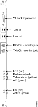
| Connector/Indicator | Function |
|---|---|
Y1Trunk INPUT/OUTPUT | DB15 connector for Y1 Trunk |
Line in | Y1 trunk input line |
Line out | Y1 trunk output line |
RX MON | BNC test connector for monitoring receive Y1 line |
TX MON | BNC test connector for monitoring transmit Y1 line |
LOS light (red) | Indicates loss of signal at the local end. |
Red alarm light (red) | Indicates loss of local frame alignment. |
Yellow alarm light (yellow) | Indicates loss of frame alignment at the remote end. |
AIS light (green) | Indicates the presence of all ones on the line. |
FAIL light (red) | Indicates an error occurred. (First, reset the card with resetcd f. If the LED comes on again, call Customer Service.) |
ACTIVE light (green) | The card is in service and has active circuits. |
The BTM card set consists of the BTM front card and either an AIT-T3, AIT-E3, AIT-E2, or AIT-HSSI back card. The card set works in the following arrangements:
The BTM/AIT card set can operate in either simple gateway or complex gateway mode. Complex gateway supports network interworking, which allows StrataCom frame relay interfaces to communicate in a tiered network. Network interworking requires release 8.1 or higher system software. For a description of tiered networks, trunks, ATM protocols, and cell and header formats, refer to the System Manual.
Simple gateway supports frame relay connections that terminate on either an IPX or IGX in a flat network. Simple gateway does not support frame relay connections between the AXIS FRSM and the IGX FRM/FRI card set and does not require 8.2 system software.
The faceplate of the BTM has four LEDs. The ACTIVE LED indicates the card is active and functioning. A BTM card failure triggers the FAIL LED. The other two LEDs are a summary alarm for the AIT back card conditions. A yellow MINOR LED indicates either a fault that does not interrupt service or that error statistics have exceeded a preset threshold. A red MAJOR LED indicates a service-affecting failure. See Figure 3-8 .
The BTM card set requires no maintenance. If a BTM card set has either a solid or a confirmed intermittent failure, replace it. The only indicators on the BTM faceplate are the ACTIVE and FAIL LEDs. For purposes of troubleshooting, you should view the BTM/AIT card set as a trunk. The tstcon command does not work on a BTM because the card cannot be isolated from the IGX or the other, connected BTM.
A trunk loopback test is run when the BTM detects an integrated alarm. The loopback test verifies if the line or the card is faulty. A loopback test "pass" means the line is faulty and a line alarm is indicated. A loopback test "fail" means the card is faulty. In the case of a faulty card, a switch to a Y-Cable equipped redundant card occurs if available.

The back card provides the interface to the trunk line and performs all necessary CRC generation and checking. The following BTM back cards:
The HSSI connector is a 50-pin connector. The other trunk ports consist of one BNC connector for transmit and one BNC connector for receive. The back card faceplate has six LED indicators. They indicate the status of the port and various alarm conditions (see Figure 3-9 and Table 3-12 for details).
The AIT -T3 back card has two BNC connectors and six LED indicators, as Figure 3-9 shows. Table 3-12 lists these faceplate items. When you correlate the items in the figure and table, read from the top.

| Connector/Indicator | Function |
|---|---|
Transmit Jack | BNC connector for transmit data. |
Receive Jack | BNC connector for receive data. |
LOS light (red) | Loss of signal at the local end. |
Red alarm light (red) | Loss of local T3 or E3 frame alignment or loss of cell alignment. |
Yellow alarm light (yellow) | Loss of frame alignment at remote end or loss of cell alignment. |
AIS light (green) | All ones on the line. |
FAIL light (red) | An error was detected. (Resetting the card with resetcd f may clear it. If the LED comes on again, call Customer Service.) |
ACTIVE: light (green) | The card is in service and has active circuits. |
The AIT-HSSI back card supplies a single HSSI interface to the AIT trunk. For its implementation, the AIT-HSSI requires an external DSU such as an inverse mux or a fractional T3 DSU. Figure 3-10 shows the faceplate of the AIT-HSSI.
The range of bit rates for the AIT-HSSI on a BTM is 4 Mbps to 16 Mbps. The range of rates is across aggregated T1 channels. The command that configures the rate is cnftrk. The dsptrkcnf command displays the existing parameters for a trunk. For specifications on HSSI, refer to the appendix titled "System Specifications."
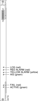
The AIT-E2 back card supplies a single E2 interface to the 16-Mbps BTM front card. The line rate is 8.448 Mbps. The AIT-E2 operates between only StrataCom nodes, so it does not support a UNI interface. For specifications on this E2 line, refer to the appendix titled, "System Specifications." Figure 3-11 shows the AIT-E2 faceplate.

The BTM card set supports Y-cable redundancy on ATM trunks in IGX-to-IGX, IGX-to-IPX and IGX-to-BPX applications. Y-cable redundancy is an IGX feature that you can apply to ATM trunks. (In the Command Reference, see commands addyred, delyred, dspyred, and ptyred.) Before you assign Y-cable redundancy, you must have upped (uptrk) and added (addtrk) both cards.
The BTM performs a clock test on the input line source. If either the clock or the card fails, a switchover occurs to a Y-cabled, redundant BTM trunk card set if one is available. If the switchover occurs, the primary ATM trunk card acquires failed status, and the red FAIL indicator turns on. If Y-cable redundancy is not available, the ATM trunk switches to another clock source and marks the line as a failed clock source.
The ATM Line Module B (ALM/B) card set provides a trunk with a full T3 or E3 rate. Back cards for the ALM/B are the BC-UAI-1T3 and the BC-UAI-1E3. They support either a single T3 trunk or a single E3 trunk. For characteristics of T3 and E3 trunks, refer to the appendix titled "System Specifications." For information on how to bring up an ALM/B trunk, refer to the IGX Installation Manual. Figure 3-12 illustrates an ATM cloud using the ALM/B.
The ALM/B supports the following:
The ALM/B card set consists of the ALM/B front card and either a BC-UAI-1T3 or a BC-UAI-1E3. The card set works in the following arrangements:
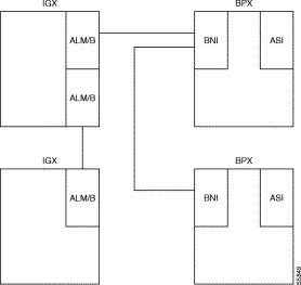
On a per-connection basis, the ALM/B operates in either simple gateway or complex gateway mode. System software determines the mode according to the type of connection. Complex gateway supports network interworking, which allows StrataCom frame relay interfaces to communicate efficiently over ATM trunks. Complex gateway also allows frame relay interfaces to interwork to BPX/AXIS endpoints such as an FRSM on an AXIS shelf. Simple gateway supports connection types that terminate on either an IPX or IGX. For more detailed descriptions of complex and simple gateway modes, trunks, ATM protocols, and cell and header formats, refer to the System Manual.
The ALM/B card set requires no maintenance. If an ALM/B card set has either a solid or an intermittent but confirmed failure, replace it. The only indicators on the ALM/B faceplate are the ACTIVE and FAIL LEDs. For purposes of troubleshooting, you should view the ALM/B card set as a trunk. The tstcon command does not work on an ALM/B because the card cannot be isolated from the IGX or the other, connected trunk card set.
A trunk loopback test executes when the ALM/B detects an integrated alarm. The loopback test determines if the line or the card is faulty. A loopback test "pass" means the line is faulty, so a line alarm is flagged. A loopback test "fail" means the card is faulty. If a card is faulty and a Y-cabled secondary is available, a switch to the secondary card occurs.
The faceplate of the ALM/B has four LEDs. See Figure 3-13 .The ACTIVE LED indicates the card is active and functioning. An ALM/B card failure triggers the FAIL LED. The other two LEDs are a summary alarm for the back card conditions. A yellow MINOR LED indicates either a fault that does not interrupt service or that error statistics have exceeded a preset threshold. A red MAJOR LED indicates a service-affecting failure.
The ALM/B card set supports Y-cable redundancy on ATM trunks in IGX to IGX, IGX to IPX and IGX to BPX applications. (In the Command Reference, see descriptions of addyred, delyred, dspyred, and ptyred.)
Y-cable redundancy requires that both cards are upped (uptrk) and added (addtrk) before you assign redundancy with the addyred command.
The ALM/B performs a clock test on the input line source. If either the clock or the card fails, a switchover occurs to a Y-cabled, redundant ALM/B trunk card set if one is available. If the switchover occurs, the primary ATM trunk card acquires failed status, and the red FAIL indicator turns on. If Y-cable redundancy is not available, the ATM trunk switches to another clock source and marks the line as a failed clock source.

The back card provides the interface to the trunk line and performs all necessary CRC generation and checking. The following are the ALM/B back cards:
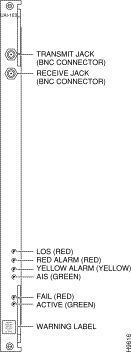
The trunk ports consist of one BNC connector for transmit data and one BNC connector for receive data. The back card faceplate has six LED indicators. The LEDs indicate the status of the port and various alarm conditions. See Figure 3-14 and Table 3-13 for details on the T3 card and Figure 3-15 and Table 3-14 for details on the E3 card. Correlate items in each figure and table as you read from the top down. For technical specifications on T3 and E3 lines, see the appendix titled "System Specifications."
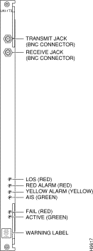
| Connector/Indicator | Function |
|---|---|
Transmit jack | BNC connector for transmit data. |
Receive jack | BNC connector for receive data. |
LOS light (red) | Loss of signal at the local end. |
Red alarm light (red) | Loss of local T3 or E3 frame alignment or loss of cell alignment. |
Yellow alarm light (yellow) | Loss of frame alignment at remote end or loss of cell alignment. |
AIS light (green) | All ones on the line. |
FAIL light (red) | An error was detected. (Resetting the card with resetcd f may clear it. If the LED comes on again, call Customer Service.) |
ACTIVE light (green) | The card is in service and has active circuits. |
| Connector/Indicator | Function |
|---|---|
Transmit Jack | BNC connector for transmit data. |
Receive Jack | BNC connector for receive data. |
LOS light (red) | Loss of signal at the local end. |
Red alarm light (red) | Loss of local T3 or E3 frame alignment or loss of cell alignment. |
Yellow alarm light (yellow) | Loss of frame alignment at remote end or loss of cell alignment. |
AIS light (green) | All ones on the line. |
FAIL light (red) | An error was detected. (Resetting the card with resetcd f may clear it. If the LED comes on again, call Customer Service.) |
ACTIVE: light (green) | The card is in service and has active circuits. |
![]()
![]()
![]()
![]()
![]()
![]()
![]()
![]()
Posted: Mon Sep 16 17:10:13 PDT 2002
All contents are Copyright © 1992--2002 Cisco Systems, Inc. All rights reserved.
Important Notices and Privacy Statement.