|
|

This chapter describes the hardware and related functions for each model of the IGX. For IGX enclosures, this chapter describes:
A brief description of optional peripherals and third-party equipment appears at the end of the chapter. For system specifications, such as protocols and standards, refer to Appendix A.
For all matters relating to installation, troubleshooting, user-commands, and repair and replacement, refer to the IGX Installation Manual.
Other manuals that relate to IGX operation are:
An IGX system is available in the following models:
The standard IGX 8 enclosure is a standalone. By using the rack-mounting parts that come with the IGX 8, you can mount it in a standard 19" rack. The installation uses standard EIA spacing between vertical rails. Also, the vertical spacing between components, such as the card cage and fan tray, must be in the range 0.047" to 0.077" (0.119 cm to 0.196 cm). The IGX 8 rack-mount cabinet contains:
Figure 2-1 and Figure 2-2 show the rack-mount IGX 8 in front and back views, respectively.
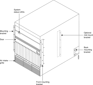
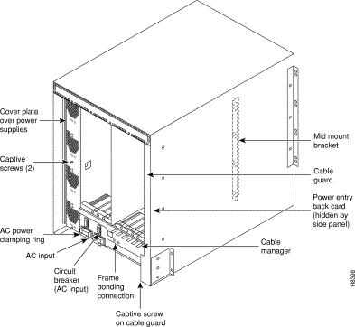
The IGX 8 stand-alone system comes in a free-standing enclosure with a tool-operated front door latch. Four plastic feet support the IGX 8 stand-alone at its base.

The stand-alone enclosure holds all of the system modules, power modules, power supplies, and cooling fans. The IGX 8 cabinet contains one eight-slot card cage with a backplane into which front cards plug, three auxiliary slots, a fan tray with four fans, an exhaust plenum, a power entry module, and an optional AC Power Tray that holds up to four power supplies. Figure 2-3 is a front view of the IGX 8 stand-alone.
The IGX 16 stand-alone system comes in a free-standing enclosure with a tool-operated front door latch. Side panels attach to the unit on vertical mounting rails at each corner of the unit. The four wheels at the base of the stand-alone unit allow the unit roll into position. The unit also includes levelers. With the unit at the appropriate location, you can adjust the height of the levelers to make the unit immobile. The wheels and feet are removable, so you can secure the standalone IGX 16 to the floor with four .250-20 fasteners.
The IGX 16 stand-alone enclosure holds all of the system modules, including:
Figure 2-4 shows a front view of the position of the major components of the IGX 16 Stand-alone. Figure 2-5 shows a view of an AC-powered IGX 16 from the back.


The IGX 16 stand-alone system has a free-standing enclosure with a tool-operated front door latch. Side panels attach to the unit on vertical mounting rails at each corner of the unit. The four wheels at the base of the stand-alone unit allow the unit roll into position. The unit also includes levelers. With the unit at the appropriate location, you can adjust the height of the levelers to make the unit immobile. The wheels and feet are removable, so you can secure the standalone IGX 32 to the floor with four .375-16 fasteners.
The IGX 32 stand-alone enclosure holds all of the system modules, including:
Figure 2-6 shows a front view of the position of the major components of the IGX 32 Stand-alone. Figure 2-7 is a view of the back of an AC-powered IGX 16.

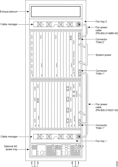
The IGX 16 rack-mount system is mounted in a standard 19" rack, such as a STRATM cabinet. This installation uses standard EIA spacing between vertical rails. Also, the vertical spacing between components, such as the card cage and fan tray, must be in the range .047" to .077" (0.119 cm to 0.196 cm).
The IGX 16 cabinet includes:
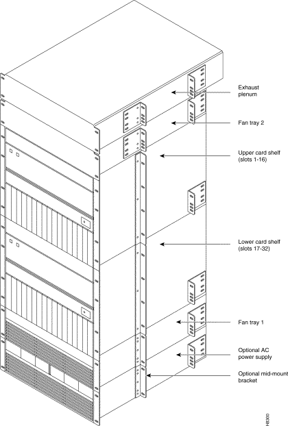
The IGX 32 rack-mount system can be rack-mounted in a standard 19" rack. This installation uses standard EIA spacing between vertical rails. Also, the vertical spacing between components, such as the card cage and fan tray, must be in the range .047" to .077" (0.119 cm to 0.196 cm).
The IGX 32 cabinet includes:
The two IGX backplanes connect through an interconnect cable. Figure 2-8 and Figure 2-9 show the location of the major components of an IGX 32.
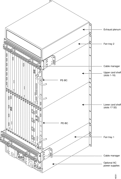
This section describes the Power Entry Back Card (PE-BC), the Power Entry Module (PEM), and the fan tray power connections to the PE-BC.
For all IGX models, the type of power supplied at the unit can be either AC or DC. In a unit that uses a DC source, the power cord is attached to a Power Entry Module (PEM). The PEM provides circuit protection for the DC voltage. In a unit that uses an AC source, an AC power supply module is necessary for generating the DC voltages for the backplane and cooling fans.
Each shelf of an IGX requires a PE-BC. For the IGX 8 and standalone versions of the 16 and 32, the card cage ships with the PE-BC already in place. For rack-mount versions of the IGX 16 and 32, you must install the PE-BC. Because of its shape, the PE-BC is also called the "E card."
In both AC-powered and DC-powered systems, the PE-BC connects the -48 VDC primary power for the system to the backplane. It also routes power to the fan tray. In an AC-powered system, a cable from the supply module plugs into the PE-BC. In a DC-powered system, the PE-BC must have at least one PEM. Figure 2-10 shows a PE-BC for an AC-powered system.
The slot for the PE-BC has no number. It plugs into the slot on the right of back-slot 1. If the enclosure is an IGX 32, a PE-BC also goes in the slot to the right of back-slot 32. Figure 2-11 shows the location of a PE-BC in an IGX 8 as an example.
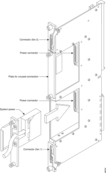
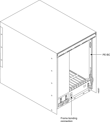
A PEM is a small card that plugs into a connector on the PE-BC. (The PEM plugs into the same connector as a cable from the power supply module in an AC-powered system.) A PEM takes the DC power directly from the DC power source in the building, filters it, and passes it to the PE-BC. A PEM also has a circuit breaker and a strain-relief clamp for the DC power cable. Figure 2-12 shows a PEM plugged into a PE-BC in a non-redundant system. It also shows the blank plate that covers an unused connection in a non-redundant system. Redundancy of DC sources and PEMs lets the system continue to operate in case one of the two independent DC branch circuits fails. The IGX Installation Manual describes the DC power setup.
In an IGX 8 or 16, power to the fan tray comes from the "Fan 1" connector on the PE-BC (see Figure 2-12). In an IGX 32, the booster fan at the top receives power at the Fan 2 connector. The lower tray uses the two Fan 1 connectors. The IGX Installation Manual describes fan installation.

This section introduces the AC power system first for the IGX 8 and then the IGX 16/32.
For an IGX 8 to use an AC power source, an AC power supply system is necessary. The IGX 8 power supply housing holds up to four, 400-Watt power supplies. The AC system provides the system with -48 VDC from 100 to 240 VAC input. The AC power supply housing is between the card cage and the side wall of the node. The IGX 8 has one or, with AC redundancy, two AC power inputs.
Two types of redundancy exist: power source redundancy, in case one AC circuit fails, and AC power supply redundancy, in case a supply fails. Figure 2-13 shows two AC inputs.

The minimum requirement for an AC-powered system is one AC source and one power supply. One supply is adequate for four cards unless you specify power supply redundancy. See Table 2-1 for power supply requirements. Figure 2-14 shows the power supply slot designations and external parts of the supplies.
Figure 2-14 shows a dual-input system. Facing the back of a dual-input system, AC Input A is on the left. AC Input B in on the right. In a dual-input system, the Input A supplies power supply slots A and B. Input B supplies power to slots C and D. A single AC input system does not have these distinctions: the single input receives AC power for supplies A through C.
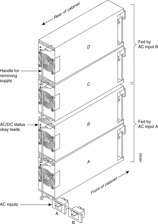
Two types of redundancy exist in the AC-powered system. One redundancy is that of AC power inputs. A redundant AC power source from a building circuit that is independent of the other AC circuit provides backup if one AC circuit at the site fails. The other redundancy is that of the 400-Watt power supply modules. Redundancy of the 400-Watt power supplies provides a backup if a power supply fails.
In supporting single and dual AC inputs, power supply arrangements differ, as follows:
Table 2-1 shows the minimal 400-Watt unit requirements for different IGX 8 configurations. The factors that determine the number of supplies are as follows:
In Table 2-1, the System column shows the number of AC inputs. The Number of Cards column shows the number of cards at the cutoff point for more supplies. The Supply Redundancy column indicates whether the configuration includes a redundant supply for backup. For columns A through D, an X shows that the corresponding slot in the power supply housing must have a power supply to meet the configuration requirements. The part number for a power supply is 400W-PS-AC.
| System | Number of Cards | N+1 Supply Redundancy | A | B | C | D |
|---|---|---|---|---|---|---|
1 AC Input | 4 or less | No | X |
|
|
|
4 or less | Yes | X | X |
|
| |
more than 4 | No | X | X |
|
| |
more than 4 | Yes | X | X | X |
| |
2 AC inputs | 4 or less |
| X |
| X |
|
more than 4 |
| X | X | X | X |
This section introduces the AC power system and explains the concept of redundancy.
For an IGX 16/32 to use an AC power source, an AC power supply shelf is necessary. The IGX 16/32 AC power tray holds up to six, 875-Watt power supplies. The AC module provides the system with -48 VDC from 208/240 VAC input. The AC power supply shelf sits below the main (lower) fan tray.
A power circuit breaker for each card shelf exists on the back panel. This allows power for each card shelf to be individually turned on and off. (An IGX 16 has two, card shelf circuit breakers, but only one is meaningful.) The back panel also contains one or—with AC redundancy—two AC power inputs. Figure 2-15 shows the back of the AC power supply section on an IGX 32 with redundancy for AC power input. In Figure 2-15, the node has a main circuit breaker on the power supply shelf for each AC power input.
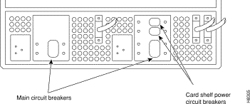
Figure 2-16 shows the possible configurations for the system power cables. Although these cables have different lengths, the pinouts are identical.
 System Power Cable Diagram in AC-Powered IGX 16/32
This section describes the AC power configuration. The power supply configuration is based on power supply redundancy and the power requirements (load) created by the cards in the system. The minimum is 1 AC source and 1 supply. This minimum applies to the IGX 16: with 12 or fewer boards, 1 supply is adequate unless redundancy is specified. Figure 2-17 shows the power supply slot designations.
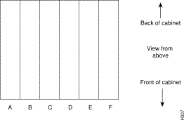
Two types of redundancy exist in the AC power supply configuration. One redundancy is that of AC power inputs. A redundant AC power source from a building circuit that is separate from the other AC circuit provides backup if one AC circuit at the site fails. The other redundancy is that of the 875-Watt power supply modules. Redundancy of the 875-Watt supplies provides a backup if a supply fails.
In supporting the two types of redundancy, power supply arrangements differ, as follows:
Table 2-2 shows the required number of power supplies for IGX 16/32 systems. In Table 2-2, the locations for primary (or minimal) power supplies are marked with an X. The primary supplies reflect redundancy of AC inputs and backup supplies. An O indicates a slot that must have a supply because the card cage contains more than 12 boards.
In Table 2-2, the System column lists the IGX model number coupled with the number of AC inputs and whether the single-AC input models have power supply redundancy. The table also shows slot locations A to F and the part number of the kit that contains all the pieces for the item in the System column. Extra supplies for more than 12 boards (O) are not a part of a kit under Kit Part No. but have another part number. The part number of a supply ordered to fill extra power demands is IGX-AC-PS.
| System | A | B | C | D | E | F | Kit Part No. |
|---|---|---|---|---|---|---|---|
IGX 16: 1 AC input, no power supply redundancy | X | O |
|
|
|
| IGX16-AC1-1 |
IGX 16: 1 AC input, with power supply redundancy | X | X | O |
|
|
| IGX16-AC2-1 |
IGX 16: 2 AC inputs | X | O |
| X | O |
| IGX16-AC2-2 |
IGX 32:1 AC input, no power supply redundancy | X | X | O |
|
|
| IGX32-AC2-1 |
IGX 32: 1 AC input, with power supply redundancy | X | X | X | O |
|
| IGX32-AC4-1 |
IGX 32: 2 AC inputs | X | X | O | X | X | O | IGX32-AC4-2 |
Note that, with all power supply configurations, power supply locations begin at the lowest lettered slot on either side, and the occupied positions are contiguous. For example, in a dual-AC system with four supplies, the occupied slots should not be A, C, D, and F. Rather, the supplies should occupy slots A, B, D, and E.
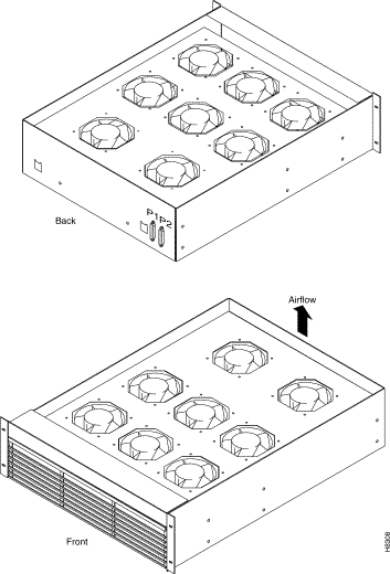
Mounted fans in a fan tray cool the system. In an IGX 8, the fan tray with four fans resides immediately below the card cage. Figure 2-18 shows the IGX 8 fan tray. In an IGX 16 or 32, a fan tray sits immediately below the card cage and, if the system uses AC power, above the power supply module. An IGX 32 also has a booster fan tray above the upper card cage. Figure 2-19 shows front and back views of the fan tray for an IGX 16 or 32.
An exhaust plenum resides at the top of each unit. Cooling air for the cards enters through a grille on the front of the fan tray beneath the card cage and exits through the rear of the exhaust plenum. In an IGX 32, the booster fan tray has no grille.

To maintain correct air flow and reduce Radio Frequency Interference (RFI) and Electromagnetic Interference (EMI), all unused back card slots must be covered with the blank faceplates that StrataCom provides.
An IGX card cage has 8, 16, or 32 active card slots on each side of the backplane. The PE-BC slot has no number in this scheme. An IGX 8 also has space for three spare cards.
In most cases, front slots contain data processing cards, such as processors, service modules, and so on. With the exception of the System Clock Module (SCM), the back slots contain system interface cards. The plug-in cards in the front slots are the system unit cards. The cards in the back slots are the network trunk and user interface cards. For a description of the cards, refer to the next chapter.
Figure 2-20 and Figure 2-21 show typical card placements in an IGX 8. Figure 2-22 and Figure 2-23 show typical card placements in an IGX 16 (front) and 32 (back), respectively. Most cards can reside in any vacant slot. Only the NPM and SCM have reserved slot locations.


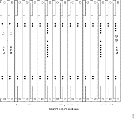

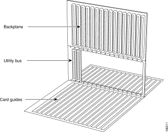
The IGX 8 backplane has eight 216-pin connectors. Each IGX 16/32 backplane has sixteen 216-pin connectors and occupies just over half the height of the card cage. The backplane is in the upper part of the card cage and connects up to 16 front cards. Figure 2-24 shows a front view of an IGX 16 backplane. Except for having 8 fewer card slots, the IGX 8 card cage looks the same as the IGX 16 backplane. The utility bus resides beneath the NPM slots at the left. The figure also shows the card guides in the front and rear. Each front card plugs into the backplane at the upper connector (P1). In addition to providing the physical connections between the cards, the backplane contains the system bus. The backplane is also called the midplane.
In the IGX 32, the upper and lower card cages are slightly different. The upper card cage has a utility bus beneath the backplane for the NPMs and SCM. See Figure 2-24. The lower card cage in the IGX 32 has a backplane with no utility bus because only service cards exist on the lower shelf.
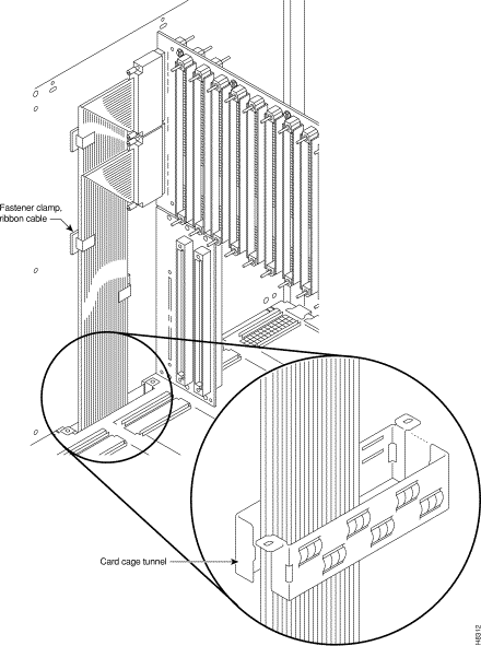
In an IGX 32, a pair of ribbon cables carries the backplane signals between the upper and lower shelves. These ribbon cables pass through a cut-out space in the card cages. They also go through a two-piece conduit that fits together to surround the cables. The name of this two-piece conduit is the card cage tunnel. The cables connect to two, 100-pin connectors that reside on the front side of the backplane (the opposite side of the backplane from the Power Entry Back Card). Figure 2-25 illustrates the expansion connectors, the ribbon cables, the cutout space, and the card cage tunnel. The card cage tunnel is shown in place in the main figure and prior to insertion in the blown-up view.
The IGX system bus resides on the backplane. The system bus provides the following:
2
As a safeguard against card driver failure or bus failure, the backplane contains redundant system buses. In a two-shelf system, a cable between the upper and lower backplanes extends the system bus to the lower shelf. The earlier section "Backplane (Midplane)" describes this cable. The backplane also contains fuses to protect it from catastrophic electrical damage. (See the chapter on repair and replacement in the IGX Installation Manual.)
A utility bus is used to interconnect redundant processor cards in a node. In an IGX, the two-slot utility bus UBS-2 interconnects the two processor cards. It occupies the positions of the lower connectors in slots 1 and 2.
![]()
![]()
![]()
![]()
![]()
![]()
![]()
![]()
Posted: Mon Sep 16 17:04:53 PDT 2002
All contents are Copyright © 1992--2002 Cisco Systems, Inc. All rights reserved.
Important Notices and Privacy Statement.