|
|

This chapter introduces the Dial Access Switching (DAS) system, which consists of the DAS Server Shelf (the hardware) and the Dial-Up Frame Relay application (the software). It contains the following sections:
The DAS Server Shelf is a rack-mounted adjunct processor connected to a Cisco WAN switching node typically through an IGX Frame Relay Module (FRM), an IPX Frame Relay Port (FRP), or a BPX switch with an MGX 8220 Frame Relay Service Module (FRSM). The DAS Server Shelf must also have IP connectivity to a StrataView Plus Workstation.
Figure 1-1 shows the DAS Server Shelf along with some of the other components that compose a Dial-Up Frame Relay network.

The Dial Access Switching system is added to Cisco WAN switching networks through two components:
The DAS Server Shelf, the hardware component of the Dial-Up Frame Relay application, is a rack-mounted adjunct processor. This scalable UNIX platform comes in four models:
All DAS Server Shelf models feature:
The DAS Server Shelf is typically connected to a co-located Cisco wide area switch through a frame-relay (V.35) port. The DAS Server Shelf is also connected to the StrataView Plus Workstation. When the StrataView Plus Workstation is located close by, the DAS Server Shelf and StrataView Plus Workstation can be connected to the same Ethernet segment. When the StrataView Plus Workstation and the DAS Server Shelf are not located close enough to be connected to the same Ethernet segment, they are connected through a frame relay PVC configured to provide IP connectivity (that is, IP over frame relay).
The DAS Dial-Up Frame Relay software is distributed, using a client-server architecture, between the DAS Server Shelf and the DAS Daemon software that runs on the StrataView Plus Workstation.
The DAS Server Shelf, which runs the client software to control application-specific ISDN call processing, includes the following components:
Since all ISDN switch manufacturers have not implemented ISDN signalling in exactly the same way, Cisco has developed DAS software to work with the major signaling variations and switches used around the world. There are seven ISDN switch software variants supplied with the standard Dial-Up Frame Relay application software:
The integrated services digital network (ISDN) technology allows for the creation of a worldwide public telecommunications network that delivers a variety of voice and data services. While it is not yet universal, ISDN services are becoming increasingly available. These pockets or islands of ISDN do provide standardized interfaces for enterprise networks.
Typically, ISDN connections are provided through a Basic Rate Interface (BRI) or a Primary Rate Interface (PRI). The BRI provides two 64 kbps channels for user data, known as B (or bearer) channels, and a signalling channel. Currently, the BRI is the most common user interface into an ISDN network. Providing 23 64-kbps B channels and a signalling channel, the PRI implements ISDN trunks. For either interface, the signalling channel is referred to as a D channel. D channels provide the signalling information for all its associated B channels. The PRI is therefore referred to as 23B+D, and the BRI is referred to as 2B+D.
Each B channel is equivalent to a DS0 channel in a T1 signal and is capable of carrying user data at a rate of 64 kbps. The D channel in a PRI is also a 64 kbps channel, so the 24 ISDN PRI channels (i.e., 23B+D) can be carried over T1 facilities. (The European ISDN PRI consists of 30 B channels and one D channel and likewise corresponds to the E1 transmission rate and is carried over E1 facilities.)
The D channel is devoted to transporting message-oriented signalling information. These messages set up, maintain, and terminate B-channel connections. ISDN D-channel signalling is essentially a group of related protocols, complying with the Q.921 and Q.931 ITU standards. Q.921 frames are formatted very similarly to frame-relay frames and hence the node's frame-relay interface cards may be used to interface to ISDN PRI trunks at the physical level. The Cisco Dial Access Switching (Dial-Up Frame Relay) system interprets D-channel messages and activates semi-permanent virtual circuits (SPVCs) to route the ISDN calls through frame-relay networks.
A single Cisco DAS Server Shelf can manage up to 20 PRIs.
Frame relay provides a standard interface to the wide-area network for bridges, routers, front-end processors (FEPs), and other LAN devices. A frame relay interface is designed to act like a wide-area LAN--it relays data frames directly to their destinations at very high speeds. Frame relay frames travel over predetermined virtual circuit paths, are self-routing, and arrive at their destination in the correct order.
Frame relay connections are identified by their Data Link Connection Identifier (DLCI), which identify logical connections within a shared physical channel. Network nodes normally route frames through a frame-relay network based on their DLCIs. Frames with the same DLCI are associated with the a single logical channel.
The Cisco WAN Switching System Overview contains further information about Cisco WAN switching networks and Frame Relay connections.
A virtual circuit only allocates a physical connection when there is data to send. The connection between two devices is set up at the start of transmission, or when the network is configured. A PVC is similar to a dedicated private line because the connection is set up on a permanent basis.
A semi-permanent virtual circuit is a PVC that is configured in the system's database but is not activated until some event occurs. SPVCs, which are also referred to as soft PVCs, effectively conserve the network's resources until they are actually needed by a user.
The DAS Dial-Up Frame Relay application operates through both the DAS Server Shelf and StrataView Plus Workstation. It configures frame-relay PVCs through a Cisco frame-relay network. These connections lie dormant in the database on the StrataView Plus Workstation until they are activated by an ISDN call into the network. During the DAS Dial-Up Frame Relay application configuration, the PVC has been associated to an ISDN call to a specific number through the Automatic Number Identification (ANI) feature. A single ISDN call can activate up to seven dormant PVCs. During operation when an ISDN call with that number (the ANI) is validated, StrataView Plus activates the dormant PVC between two preconfigured endpoints. When the call is terminated, the StrataView Plus returns the PVC to the its dormant state.
During a dial-up or dial-backup call, the DAS Server Shelf client software performs ISDN call processing and requests connections from the DAS Daemon on the StrataView Plus Workstation. The StrataView Plus Workstation, with the DAS Daemon software, performs the connection management function and directs the frame-relay network to set up and take down the virtual circuits. DAS Dial-Up Frame Relay events are also recorded in the StrataView Event Log.
You configure DAS Server Shelf functions by using the DAS Dial-Up Frame Relay Command Line Interface (CLI). The DAS CLI can be accessed either through a remote connection, such as Telnet, or from a directly-connected dumb terminal (e.g., VT-100). Connections must be configured in the DAS database before an ISDN call is received. These connections are configured with StrataView Plus Automatic Numbering Identifier (ANI) interface and Connection Management windows. (The bulk of this publication describes the different tasks required to configure the DAS Server Shelf and the StrataView Plus connections.)
Two types of connections are preconfigured in the StrataView Plus database:
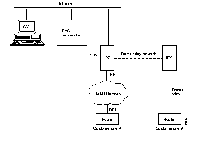
For the example shown in Figure 1-2, a PVC is configured in the StrataView Plus database between the routers at Customer Sites A and B. (In actuality, the PVC is configured between the ports on the Cisco wide-area switches which connect to these routers, that is, the ports on the two IGX switches.)

To begin a dialup process, customer premise equipment, such as the router at Customer Site A, issues call setup commands to the ISDN network. The ISDN network routes the incoming call to the PRI access port of the Cisco WAN switching frame-relay network (i.e., IGX or IPX switch). These call requests and call setup messages are carried on the ISDN D channel. The IGX (or IPX) switch passes the ISDN message, encapsulated in an V.35 frame-relay frame, to the DAS Server Shelf. The DAS processes this message and initiates DAS server function on the StrataView Plus Workstation. The DAS server searches the database for the appropriate connection information which has previously been configured (e.g., a virtual connection to Customer Site B), then passes this information to the frame-relay network. In other words, the DAS Dial-Up Frame Relay determines the identity of the calling device (using the ANI) and directs the frame-relay network to activate the virtual circuits associated with the call source.
Once the dial up connection is established, all of the routing, switching and (when needed) rerouting are handled by Cisco wide-area switches (i.e., nodes) in the same way that they are handled for PVCs that are connected with leased access lines. When the call is terminated, the virtual circuits are torn-down in a similar manner.
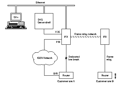
ISDN Dial-up Frame Relay provides a reliable, economical dial backup solution by using an ISDN switched connection as the backup link into the frame relay network. If the site's leased line connection to the network fails, a dial-up ISDN backup link, shown in Figure 1-3, can quickly and automatically re-establish communications. If the network offers the capability to provide a pool of ports to support dial-in users, the possibility of a single failed port disrupting communication is minimal.

The call processing is similar to that of the Dial-Up Call Process, except that the ISDN call is initiated automatically, and the original PVC for the dedicated line is torn down. Because Dial-Backup calls are associated with an active PVC (i.e., normal mode frame-relay connection), they must use the DLCI of the original circuit. When the router at Customer Site A senses that the dedicated line to the frame-relay network is down, it will after a configured delay, automatically dial into the ISDN network. This call will reach the DAS Dial-Up Frame Relay application, which will have already been configured to process this backup call. First it will tear down the PVC that was supporting the dedicated line, then it will establish the dial-backup PVC. When the endpoints terminate the dial-backup call, the backup PVC will be torn down and the original PVC re-established.
The DAS Server Shelf is typically co-located with a Cisco wide-area switch (that is, a BPX, IGX, or IPX switch). These network elements can also be co-located with the StrataView Plus Workstation. When they are close enough, the DAS Server Shelf and the StrataView Plus Workstation can be connected to the same Ethernet segment. When they are not co-located, a frame relay connection must be configured between them to provide IP over frame relay. The chapter, DAS Server Shelf Interface Connections, describes the different types of connections between the DAS Server Shelf and local and remote StrataView Plus Workstations.
The appendix, Call Detail Records, provides further information about the format and content of the CDRs.
|
|