|
|

Table Of Contents
Configuring BXM Virtual Switch Interface
Virtual Switch Interfaces and Qbins
Viewing Controllers and Interfaces
Configuring Partition Resources on Interfaces
Configuring Enhanced BXM Cards to Support 60K Connections
Assigning a Service Template to an Interface
Configuring the BXM Card's Qbin
Enabling VSI ILMI Functionality for the PNNI Controller
VSI Master and Slave Redundancy
VSI Slave Redundancy Mismatch Checking
What Happens When You Add a Controller
What Happens When You Delete a Controller
What Happens When a Slave Is Added
What Happens When a Slave is Deleted
VSI Slave Redundancy (Hot Slave Redundancy)
Class of Service Templates and Qbins
How Service Class Templates Work
Structure of Service Class Templates
Displaying Card Support for VC Merge
Displaying the Status of VC Merge
Configuring BXM Virtual Switch Interface
This chapter describes the BXM Virtual Switch Interface (VSI) and provides configuration procedures.
Contents of this chapter include:
–
VSI Masters and Slaves
–
•
–
–
–
–
–
•
•
–
For information on configuring SES PNNI controllers to work with BPX switches, refer to the Cisco SES PNNI Controller Software Configuration Guide.
For information on configuring MPLS controllers to work with BPX switches, refer to the Cisco MPLS Controller Software Configuration Guide.
Refer to Cisco WAN Switching Command Reference for details about the commands mentioned here for both PNNI and MPLS controllers. Refer to Release Notes for supported features.
Virtual Switch Interface
The Virtual Switch Interface (VSI) is a common control interface between the BPX 8650 or the
MGX 8850 switches and an external controller that supports the VSI protocol.VSIs allows a node to be controlled by multiple controllers, such as Multiprotocol Label Switching (MPLS) and the Service Expansion Shelf Private Network-to-Network Interface (SES PNNI).
When a VSI is activated on a port, trunk, or virtual trunk so that it can be used by a master controller, such as an SES PNNI or an MPLS controller, the resources of the virtual interface associated with the port, trunk, or virtual trunk are made available to the VSI. These control planes can be external or internal to the switch. The VSI provides a mechanism for networking applications to control the switch and use a partition of the switch resources.
VSI on the BPX provides:
•
•
•
•
•
•
Multiple Partitioning
VSI was implemented first on the BPX 8650 in Release 9.1, which uses VSI to perform Multiprotocol Label Switching and allowed support for VSI on BXM cards and for partitioning BXM resources between Automatic Routing Management and a VSI MPLS controller. BPX software uses a partition to identify and assign resources such as LCNs, VPIs, and bandwidth to a controller. Multiple VSI partitions may be defined on a single physical port.
Multiprotocol Label Switching
Multiprotocol Label Switching (MPLS, previously called Tag Switching) enables routers at the edge of a network to apply simple labels to packets (frames), allowing devices in the network core to switch packets according to these labels with minimal lookup activity. MPLS in the network core can be performed by switches, such as ATM switches, or by existing routers.
MPLS integrates virtual circuit switching with IP routing to offer scalable IP networks over ATM. MPLS support data, voice, and multimedia service over ATM networks. MPLS summarizes routing decisions so that switches can perform IP forwarding, as well as bringing other benefits that apply even when MPLS is used in router-only networks.
Using MPLS techniques, it is possible to set up explicit routes for data flows that are constrained by path, resource availability, and requested Quality of Service (QoS). MPLS also facilitates highly scalable Virtual Private Networks.
MPLS assigns labels to IP flows, placing them in the IP frames. The frames can then be transported across packet or cell-based networks and switched on the labels rather than being routed using IP address look-up.
A routing protocol such as OSPF, uses the Label Distribution Protocol (LDP) to set up MPLS virtual connections (VCs) on the switch.
MPLS Terminology
MPLS is a standardized version of Cisco's original Tag Switching proposal. MPLS and Tag Switching are identical in principle and nearly so in operation. MPLS terminology has replaced obsolete Tag Switching terminology.
An exception to the terminology is Tag Distribution Protocol (TDP). TDP and the MPLS Label Distribution Protocol (LDP) are nearly identical, but use different message formats and procedures. TDP is used in this design guide only when it is important to distinguish TDP from LDP. Otherwise, any reference to LDP in this design guide also applies to TDP.
Overview: How VSI Works
This section provides detailed reference to virtual interfaces, service templates, and Qbins.
For information on configuring SES PNNI controllers to work with BPX switches, refer to the Cisco SES PNNI Controller Software Configuration Guide.
For information on configuring MPLS controllers to work with BPX switches, refer to the Cisco MPLS Controller Software Configuration Guide.
For details about the commands mentioned here for both PNNI and MPLS controllers, refer to Cisco WAN Switching Command Reference. Refer to Release Notes for supported features.
Virtual Switch Interfaces and Qbins
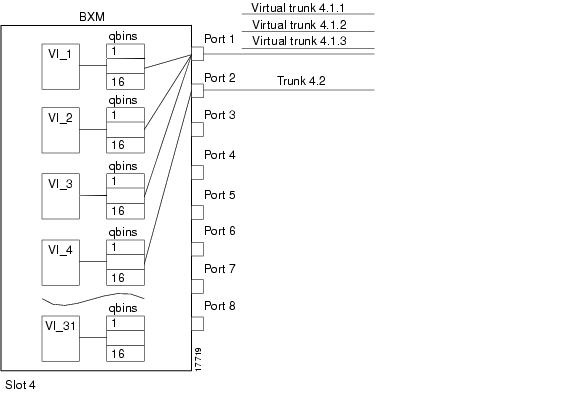
The BXM supports 31 Virtual Switch Interfaces that provide a number of resources including Qbin buffering capability. One Virtual Switch Interface is assigned to each logical trunk (physical or virtual) when the trunk is enabled (see Figure 23-1).
Each virtual switch interface has 16 Qbins assigned to it. Qbins 0 to 9 are used for Automatic Routing Management. Qbins 10 through 15 are available for use by a Virtual Switch Interface. (In Release 9.1, only Qbin 10 was used.) The Qbins 10 through 15 support Class of Service (CoS) templates on the BPX.
You may enable a Virtual Switch Interface on a port, trunk, or virtual trunk. The Virtual Switch Interface is assigned the resources of the associated virtual interface.
With virtual trunking, a physical trunk can comprise a number of logical trunks called virtual trunks. Each of these virtual trunks (equivalent to a virtual interface) is assigned the resources of one of the 31 Virtual Switch Interfaces on a BXM (see Figure 23-1).
Figure 23-1 BXM Virtual Interfaces and Qbins
VSI Master and Slaves
A controller application uses a VSI master to control one or more VSI slaves. For the BPX, the controller application and master VSI reside in an external 7200 or 7500 series router and the VSI slaves are resident in BXM cards on the BPX node (see Figure 23-2).
The controller sets up the following types of connections:
•
–
–
•
–
Figure 23-2 VSI, Controller and Slave VSI
The controller establishes a link between the VSI master and every VSI slave on the associated switch. The slaves in turn establish links between each other (see Figure 23-3).
Figure 23-3 VSI Master and VSI Slave Example
With a number of switches connected together, there are links between switches with cross-connects established within the switch as shown in Figure 23-4.
Figure 23-4 Cross-Connects and Links between Switches
Connection Admission Control
When a connection request is received by the VSI slave, it is first subjected to a Connection Admission Control (CAC) process before being forwarded to the FW layer responsible for actually programming the connection. The granting of the connection is based on the following criteria:
LCNs available in the VSI partition:
•
•
QoS guarantees:
•
•
•
When the VSI slave accepts (that is, after CAC) a connection setup command from the VSI master in the MPLS controller, it receives information about the connection including service type, bandwidth parameters, and QoS parameters. This information is used to determine an index into the VI's selected Service Template's VC Descriptor table thereby establishing access to the associated extended parameter set stored in the table.
Ingress traffic is managed differently and a preassigned ingress service template containing CoS Buffer links is used.
Partitioning
The Virtual Switch Interface must partition the resources between competing controllers, Automatic Routing Management, MPLS, and PNNI for example. You partition resources by using the cnfrsrc command.
Note
The three resources that must be configured for a partition designated ifci, which stands for interface controller 1 in this instance are listed in Table 23-1.
Table 23-1 ifci Parameters (Virtual Switch Interface)
lcns
min_lcnsi
max_lcnsi
bw
min_bwi
max_bwi
vpi
min_vpi
max_vpi
Some ranges of values available for a partition are listed in Table 23-2.
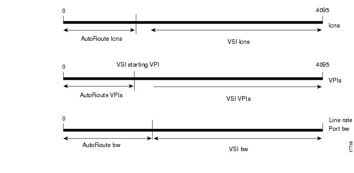
When a trunk is added, the entire bandwidth is allocated to Automatic Routing Management. To change the allocation in order to provide resources for a VSI, use the cnfrsrc command on the BPX switch.
A view of the resource partitioning available is shown in Figure 23-5.Figure 23-5 Graphical View of Resource Partitioning, Automatic Routing Management, and VSI
Multiple Partitioning
You can configure partition resources between Automatic Routing Management PVCs and three VSI controllers (LSC or PNNI). Up to three VSI controllers in different control planes can independently control the switch with no communication between controllers. The controllers are essentially unaware of the existence of other control planes sharing the switch. This is possible because different control planes used different partitions of the switch resources.
You can add one or more redundant LSC controllers to one partition, and one or more redundant PNNI controllers to the other partition. With Release 9.2.3, six new Service Class Templates were added for interfaces (for a total of nine) with multiple partitions controlled simultaneously by a PNNI controller and an LSC.
The master redundancy feature allows multiple controllers to control the same partition. In a multiple partition environment, master redundancy is independently supported on each partition.
The following limitations apply to multiple VSI partitioning:
•
•
•
•
•
•
Compatibility
The card uses a flag in the capability message to report multiple partition capability. Firmware releases that do not support multiple partitions set this flag off. The multiple partitions capability is treated as a card attribute and added to the attribute list.
Use of a partition with an ID higher than 1 requires support for multiple VSI partitions in both switch software and BXM firmware, even if this is the only partition active on a the card. In a Y-red pair configuration, the multiple partition capability is determined by the minimum of the two cards.
A card with no multiple partition capabilities will mismatch if any of the interfaces has an active partition with ID higher than 1. Attempts to enable a partition with ID higher than 1 in a logical card that does not support multiple partitions are blocked.
Resource Partitioning
A logical switch is configured by enabling the partition and allocating resources to the partition. This must be done for each of the interfaces in the partition. The same procedure must be followed to define each of the logical switches. As resources are allocated to the different logical switches, a partition of the switch resources is defined.
The resources that are partitioned amongst the different logical switches are:
•
•
•
Resources are configured and allocated per interface, but the pool of resources may be managed at a different level. The pool of LCNs is maintained at the card level, and there are also limits at the port group level. The bandwidth is limited by the interface rate, and therefore the limitation is at the interface level. Similarly the range of VPI is also defined at the interface level.
You configure the following parameters on a VSI partition on an interface:
•
•
•
•
•
•
Partitioning Between Automatic Routing Management and VSI
In addition to partitioning of resources between VSI and Automatic Routing Management, multiple partitioning allows subpartitioning of the VSI space among multiple VSI partitions. Multiple VSI controllers can share the switch with each other and also with Automatic Routing Management.
The difference between the two types of partitioning is that all the VSI resources are under the control of the VSI-slave, while the management of Automatic Routing Management resources remains the province of the switch software.
Figure 23-6 Resource Partitioning Between Automatic Routing Management and VSI
The commands used for multiple partitioning are described in Table 23-3.
Multiple Partition Example
Each logical switch can be seen as a collection of interfaces each with an associated set of resources.
Consider a BPX switch with the following four interfaces:
•
•
•
•
Also assume the resource partitioning listed in Table 23-4.
Figure 23-7 Virtual Switches
Three virtual switches are defined by this configuration:
•
10.1: 2000 lcns, 20000 cps, vpi: 1-199;
10.2.1: 10000 lcns, 10000 cps, vpi 200;
11.1: 2000 lcns, 100000 cps, vpi: 1-199}•
10.1: 4000 lcns, 30000 cps, vpi: 200-239;
11.1: 3000 lcns, 50000 cps, vpi: 200-249;
11.7.1: 5000 lcns, 200000 cps, vpi: 250-250}•
10.1: 4000 lcns, 20000 cps, vpi: 240-255;
11.1: 4000 lcns, 10000 cps, vpi: 250-255}VSI Configuration Procedures
In the VSI control model, a controller sees the switch as a collection of slaves with their interfaces. The controller can establish connections between any two interfaces. The controller uses resources allocated to its partition.
Each VSI interface can be assigned a default Class of Service template upon activation. Use the switch software CLI or Cisco WAN Manager to configure a different template to an interface.
The procedure for adding a VSI-based controller such as the MPLS controller to the BPX is similar to adding an MGX 8220 interface shelf to the BPX. To attach a controller to a node to control the node, use the addshelf command.
The VSI controllers are allocated a partition of the switch resources. VSI controllers manage their partition through the VSI protocol. The controllers run the VSI master. The VSI master entity interacts with the VSI slave running on the BXMs through the VSI interface to set up VSI connections using the resources in the partition assigned to the controller.
To configure VSI resources on a given interface, use the cnfrsrc command.
This section provides the following basic procedures:
•
•
•
•
•
Adding a Controller
To add an MPLS controller to any BXM trunk, use the addshelf command with the V (VSI) option.
To add an SES PNNI controller, use the addshelf command with an X option.
To identify VSI controllers and distinguish them from feeders, use the V (VSI) option of the addshelf command.
To add a SES PNNI controller to a BPX node through an AAL5 interface shelf or feeder type configured with VSI controller capabilities, use the addctrlr command.
If you are adding two controllers that are intended to be used in a redundant configuration, you must specify the same partition when you add them to the node by using the addshelf command.
To add an MPLS controller (or a generic VSI controller that does not need AnnexG protocol), use the following procedure.
Step 1
Step 2
Step 3
Step 4
Note that addshelf and addtrk are mutually exclusive commands; that is, you can use either addshelf or addtrk, but not both on the same interface shelf.
To add a PNNI controller, use the following procedure:
Step 1
Step 2
Step 3
Step 4
Viewing Controllers and Interfaces
Display commands such as dspnw and dspnode show interface shelves.
To view conditions on an interface shelf (feeder) trunk, use the dspnode command to identify the hub and interface shelf (feeder) nodes and shows the alarm status.
To view conditions of VSI controllers, use the dspctrlrs command to display all VSI controllers attached to the BPX. The VSI controllers are either a PNNI controller or an MPLS controller.
The designation for an Multiprotocol Label Switching (MPLS) controller serving as an interface shelf is LSC.
The external network management system can query the BPX via SNMP to discover VSI controller IDs and IP addresses.
Deleting a Controller
To delete a controller or interface (feeder) shelf, first delete it from the network. Then down the port and trunk. This applies to MPLS controllers or generic VSI controllers that do not need AnnexG protocols.
To delete an MPLS controller, use the following procedure.
Step 1
Step 2
or
Step 3
To delete a PNNI controller, use the following procedure:
Step 1
Step 2
Step 3
Step 4
Configuring Partition Resources on Interfaces
This section is key for configuring VSIs.
Prior to Release 9.1, LCNs, VPI range, and bandwidth allocation were managed exclusively by the BCC. With the introduction of VSI, the switch must allocate a range of LCNs, VPIs, and how much bandwidth for use by VSI (not BXM).
When configuring resource partitions on a VSI interface, the following commands are typically used:
•
•
•
•
•
•
•
The next step to complete when adding a VSI-based controller such as an LSC or a PNNI controller is to configure resource partitions on BXM interfaces to allow the controller to control the BXM interfaces. To do this, first create resource partitions on these interfaces. Use the cnfrsrc command to add, delete and modify a partition on a specified interface.
You may have up to three VSI controllers on the same partition (referred to as VSI master redundancy). The master redundancy feature allows multiple VSI masters to control the same partition.
The cnfrsrc parameters, ranges and values, and descriptions are listed in Table 23-5. These descriptions are oriented to actions and behavior of the BXM firmware; in most cases, objects (messages) are sent to switch software. Most of these parameters appear on the cnfrsrc screen.
Configuring Enhanced BXM Cards to Support 60K Connections
The Enhanced BXM model DX and EX can support up to 60K connections. BPX software releases prior to 9.3.30 provide support for only up to 32K connections for both VSI and non-VSI connections. Current versions of the software now allow attached VSI controllers to manage up to 60K connections per enhanced BXM card (model DX or EX). The maximum number of connections (PVCs) managed by the BCC is still at 32K.
The software automatically configures any newly installed BXM-E DX or EX cards to support 60K connections. For existing BXM-E cards that had been configured for 32K connections, a new "super user" CLI, upgdvsilcn, is provided for configuring them to support 60K connections. Once the card has been configured for 60K connections, VSI resource partitions on the card can be changed using the cnfrsrc command to take advantage of the added number of connections available for VSI.
The upgdvsilcn command can be executed on a standalone BXM configuration or Y-redundancy configuration. The command is hitless and does not impact existing connections. For a detailed discussion of the upgdvsi and related commands, refer to the Cisco WAN Switching Command Reference.
Soft and Dynamic Partitioning
Soft and Dynamic Partitioning (new in Release 9.3.10) supports smooth introduction of another VSI controller into an existing BPX network already configured with an existing VSI controller, easier tuning of switch resources, and the migration of Automatic Routing Management to PNNI.
Soft Partitioning provides resource guarantees for LCNs and bandwidth per partition and a pool of resources available to all partitions in addition to the guaranteed resources. Dynamic Partitioning provides the ability to rather easily increase the allocation of a resource to a partition.
Define and manage the number of LCNs assigned to a given VSI partition by modifying the "Minimum VSI LCNs" and "Maximum VSI LCNs" fields of the cnfrsrc CLI command.
To give more LCNs from Automatic Routing Management to VSI, change the Min LCNs or Max LCNs to cause BPX software to produce a bigger number.
To increase the LCNs reserved to a VSI partition, increase the "Minimum VSI LCNs" or "Maximum VSI LCNs" fields of the appropriate VSI partition. The VSI LCN boundary is moved into Automatic Routing Management if there are enough free Automatic Routing Management LCNs to fulfill the request.
If there are not enough free LCNs in the Automatic Routing Management (AR) space, the cnfrsrc command does not fulfill a request to increase the VSI LCN space. In such a case, the cnfrsrc command displays a failure message showing the number of currently free AR LCNs. You can reissue the cnfrsrc command specifying a smaller increase to the VSI partition. If that is not acceptable, you must first delete and reroute the necessary number of AR connections. Then you can attempt cnfrsrc again.
Moving the VSI LCN boundary into the Automatic Routing Management space might step over LCNs that are currently allocated. BPX software reprogram the necessary channels so that new channels out of the lower AR LCN space are picked instead. Before starting the process of reprogramming the necessary number of AR connections, the cnfrsrc command displays a warning message and waits for your permission to proceed. The warning message shows the number of Automatic Routing Management (AR) connections that are reprogrammed. After reprogramming the necessary channels the LCN boundary is moved into the Automatic Routing Management space.
Note
Assigning a Service Template to an Interface
The ATM Class of Service templates (or Service Class Template, SCT) provide a means of mapping a set of extended parameters. These are generally platform specific, based on the set of standard ATM parameters passed to the VSI slave in a BXM port interface during initial setup of the interface.
A set of service templates is stored in each BPX 8650 switch and downloaded to the service modules (BXMs) as needed during initial configuration of the VSI interface when a trunk or line is enabled on the BXM.
Each service template type has an associated Qbin. The Qbins provide the ability to manage bandwidth by temporarily storing cells and then serving them out based on a number of factors, including bandwidth availability and the relative priority of different Classes of Service.
When ATM cells arrive from the Edge LSR at the BXM port with one of four CoS labels, they receive CoS handling based on that label. A table look-up is performed, and the cells are processed, based on their connection classification. Based on its label, a cell receives the ATM differentiated service associated with its template type and service type (for example, label cos2 bw), plus associated Qbin characteristics and other associated ATM parameters.
A default service template is automatically assigned to a logical interface (VI) when you up the interface by using the commands upport and uptrk. The corresponding Qbin template is then copied into the card's (BXM) data structure of that interface.
Following are some examples of assigning a default service template by using the commands upport and uptrk:
•
•
•
This default template has the identifier of 1. To change the service template from service template 1 to another service template, use the cnfvsiif command.
To assign a selected service template to an interface (VI) use the cnfvsiif command, specifying the template number. It has this syntax:
cnfvsiif <slot.port.vtrk> <tmplt_id>
For example:
cnfvsiif 1.1 2cnfvsiif 1.1.1 2Use the dspvsiif command to display the type of service template assigned to an interface (VI). It has the following syntax:
dspvsiif <slot.port.vtrk>
dspvsiif 1.1dspvsiif 1.1.1To change some of the template's Qbin parameters, use the cnfqbin command. The Qbin is now "user configured" as opposed to "template configured."
To view this information, use the command dspqbin.
SCT Commands
The Service Class Template (SCT) commands are described in Table 23-6.
Configuring the BXM Card's Qbin
When you activate an interface by using an uptrk or upport command, a default service template (MPLS1) is automatically assigned to that interface. The corresponding Qbin templates are simultaneously set up in the BXMs data structure for that interface. This service template has an identifier of "1".
To change the service template assigned to an interface, use the cnfvsiif command. You can do this only when there are no active VSI connections on the BXM.
To display the assigned templates, use the dspvsiif command.
Each template table row includes an entry that defines the Qbin to be used for that Class of Service
(see Figure 23-10).This mapping defines a relationship between the template and the interface Qbin's configuration.
A Qbin template defines a default configuration for the set of Qbins for the logical interface. When a template assignment is made to an interface, the corresponding default Qbin configuration becomes the interface's Qbin configuration.
Once a service template has been assigned, you can then adjust some of the parameters of this configuration on a per-interface basis. Changes you make to the Qbin configuration of an interface affect only that interface's Qbin configuration. Your changes do not affect the Qbin template assigned to that interface.
To change the template's configuration of the interface, provide new values by using the cnfqbin command. The Qbin is now "user configured" as opposed to "template configured." This information is displayed on the dspqbin screen, which indicates whether the values in the Qbin are from the template assigned to the interface, or whether the values have been changed to user-defined values.
To see the Qbin's default service type and the Qbin number, execute the dspsct command.
Use the following commands to configure Qbins:
•
•
•
Enabling VSI ILMI Functionality for the PNNI Controller
You need to enable VSI ILMI functionality on VSI-enabled trunk interfaces when using PNNI. Note that VSI ILMI functionality cannot be enabled on trunks to which feeders or VSI controllers are attached.
To enable VSI ILMI functionality on physical trunk interfaces, use the following procedure.
Step 1
Step 2
Step 3
Step 4
To enable VSI ILMI functionality on virtual trunk interfaces, use the following procedure.
Step 1
Step 2
Step 3
Step 4
Note
To display VSI ILMI functionality on interfaces, use the dspvsipartcnf command to display the VSI ILMI status (whether enabled or not) for various VSI partitions on the interface.
VSIs and Virtual Trunking
The VSI virtual trunking feature lets you use BXM virtual trunks as VSI interfaces. Using this capability, VSI master controllers can terminate connections on virtual trunk interfaces.
Activate and configure VSI resources on a virtual trunk using the same commands you use to configure physical interfaces (for example, cnfrsrc, dsprsrc). The syntax used to identify a trunk has an optional virtual trunk identifier that you append to the slot and port information to identify virtual trunk interfaces.
A virtual trunk is a VPC that terminates at each end on the switch port. Each virtual trunk can contain up to 64,000 VCCs, but it might not contain any VPCs.
Virtual trunk interfaces cannot be shared between VSI and Automatic Routing Management. Therefore, configuring a trunk as a VSI interface prevents you from adding the trunk as an Automatic Routing Management trunk. Similarly, a trunk that has been added to the Automatic Routing Management topology cannot be configured as a VSI interface.
Virtual trunks on the BPX use a single configurable VPI. Because virtual trunk interfaces are dedicated to VSI, the entire range of VCIs is available to the VSI controllers.
The virtual trunking feature introduces the concept of defining multiple trunks within a single trunk port interface. This creates a fan-out capability on the trunk card.
Once VSI is enabled on the virtual trunk, Automatic Routing Management does not include this trunk in its route selection process.
To configure a VSI virtual trunk, use the following procedure.
Step 1
uptrk <slot.port.vtrunk>Step 2
cnftrk <slot.port.vtrunk>Step 3
cnfrsrc <slot.port.vtrunk>
VSI Master and Slave Redundancy
The ability to have multiple VSI controllers is referred to as VSI master redundancy. Master redundancy enables multiple VSI masters to control the same partition.
You add a redundant controller by using the addshelf command, the same way you add an interface (feeder) shelf, except that you specify a partition that is already in use by another controller.
The capability can be used by the controllers for cooperative or exclusive redundancy as follows:
•
Both controllers can be active in a partition, and can control the resources simultaneously.•
Only one controller is active at a time. It is up to the controllers to resolve which should be active.The switch software has no knowledge of the state of the controllers. The state of the controllers is determined by the VSI entities. From the point of view of the BCC, there is no difference between cooperative redundant controllers and exclusive redundant controllers.
For illustrations of a VSI Master and Slave, see Figure 23-3. For an illustration of a switch with redundant controllers that support master redundancy, see Figure 23-8.
Switch software supports master redundancy in the following methods:
•
•
•
The intercontroller communication channel is set up by the controllers. This could be an out-of-band channel, or the controllers can use the controllers interface information advertised by the VSI slaves to set up an intermaster channel through the switch.
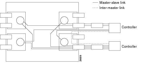
Figure 23-8 shows a switch with redundant controllers and the connectivity required to support master redundancy.
Figure 23-8 Switch with Redundant Controllers to Support Master Redundancy
The controller application and Master VSI reside in an external VSI controller (MPLS or PNNI), such as the Cisco 6400 or the MPLS controller in a 7200 or 7500 series router. The VSI slaves are resident in BXM cards on the BPX node.
Master Redundancy
You add a VSI controller, such as an MPLS or PNNI controller by using the addshelf command with the VSI option. The VSI option of the addshelf command identifies the VSI controllers and distinguishes them from interface shelves (feeders).
The VSI controllers are allocated a partition of the switch resources. VSI controllers manage their partition through the VSI interface.
The controllers run the VSI master. The VSI master entity interacts with the VSI slave running on the BXMs through the VSI interface to set up VSI connections using the resources in the partition assigned to the controller.
Two controllers intended to be used in a redundant configuration must specify the same partition when added to the node with the addshelf command.
When a controller is added to the node, switch software will set up the infrastructure so that the controllers can communicate with the slaves in the node. The VSI entities decide how and when to use these communication channels.
In addition, the controllers require a communication channel between them. This channel could be in-band or out-of-band. When a controller is added to the switch, switch software will send controller information to the slaves. This information is advertised to all the controllers in the partition. The controllers may decide to use this information to set up an intermaster channel. Alternatively, the controllers may use an out-of-band channel to communicate.
The maximum number of controllers that can be attached to a given node is limited by the maximum number of feeders that can be attached to a BPX hub. The total number of interface shelves (feeders) and controllers is 16.
Slave Redundancy
Prior to Release 9.2, hot standby functionality was supported only for Automatic Routing Management connections. This was accomplished by the BCC keeping both the active and standby cards in sync with respect to all configuration, including all connections set up by the BCC. However, the BCC does not participate in, nor is it aware of, the VSI connections that are set up independently by the VSI controllers.
Therefore, the task of keeping the redundant card in a hot standby state (for all the VSI connections) is the responsibility of the two redundant pair slaves. This is accomplished by a bulk update (on the standby slave) of the existing connections at the time that (line and trunk) Y-redundancy is added, as well as an incremental update of all subsequent connections.
The hot standby slave redundancy feature enables the redundant card to fully duplicate all VSI connections on the active card, and to be ready for operation on switchover. On bringup, the redundant card initiates a bulk retrieval of connections from the active card for fast sync-up. Subsequently, the active card updates the redundant card on a real-time basis.
The VSI Slave Hot Standby Redundancy feature provides the capability for the slave standby card to be preprogrammed the same as the active card so that when the active card fails, the slave card switchover operation can be done quickly (within 250 ms). Without the VSI portion, the BXM card already provided the hot standby mechanism by duplicating CommBus messages from the BCC to the standby BXM card.
The following sections describe some of the communication between the switch software and firmware to support VSI master and slave redundancy.
VSI Slave Redundancy Mismatch Checking
To provide a smooth migration of the VSI feature on the BXM card, line and trunk Y-redundancy is supported. You can pair cards with and without the VSI capability as a Y-redundant pair if the feature is not configured on the given slot. As long as the feature is not configured on a given slot, switch software will not perform "mismatch checking" if the BXM firmware does not support the VSI feature.
A maximum of two partitions are possible. The card uses a flag in the capability message to report multiple partition capability. Firmware releases that do not support multiple partitions set this flag to OFF. The multiple partitions capability is treated as a card attribute and added to the attribute list.
In a Y-red pair configuration, the multiple partition capability is determined by the minimum of the two cards. A card with no multiple partition capabilities will mismatch if any of the interfaces has an active partition with ID higher than 1. Attempts to enable a partition with ID higher than 1 in a logical card that does not support multiple partitions are blocked.
What Happens When You Add a Controller
You add a controller, including Label Switch Controllers, to a node by using the addshelf command. You add a redundant controller in the same way, except that you specify a partition that may already be in use by another controller. The addshelf command allows for the addition of multiple controllers that manage the same partition.
Use the addctrlr command to attach a controller to a node for the purposes of controlling the node for controllers that require Annex G capabilities in the controller interface. Note that you must first add the shelf by using the addshelf command.
You add VSI capabilities to the interface by using the addctrlr command. The only interface that supports this capability is an AAL5 feeder interface.
When adding a controller, you must specify a partition ID. The partition ID identifies the logical switch assigned to the controller. The valid partitions are 1 and 2. The user interface blocks the activation of partitions with ID higher than 1 if the card does not support multiple partitions.
To display the list of controllers in the node, use the command dspctrlrs.
The functionality is also available via SNMP using the switchIfTable in the switch MIB.
You can add one or more redundant MPLS controllers to one partition, and one or more redundant PNNI controllers to the other partition.
When using the addshelf command to add a VSI controller to the switch, you must specify the controller ID. This is a number between 1 and 32 that uniquely identifies the controller. Two different controllers must always be specified with different controller IDs.
Note
The management of resources on the VSI slaves requires that each slave in the node has a communication control VC to each of the controllers attached to the node. When a controller is added to the BPX by using the addshelf command, the BCC sets up the set of master-slave connections between the new controller port and each of the active slaves in the switch.
The connections are set up using a well known VPI.VCI. The value of the VPI is 0. The value of the VCI is (40 + (slot - 1)), where slot is the logical slot number of the slave. These values are default. You can modify them by using the addctrlr command.
Note
The addition of a controller to a node will fail if there are not enough channels available to set up the control VCs in one or more of the BXM slaves.
The BCC also informs the slaves of the new controller through a VSI configuration CommBus message (the BPXs internal messaging protocol). The message includes a list of controllers attached to the switch and their corresponding controller IDs. This internal firmware command includes the interface where the controller is attached. This information, when advertised by the slaves, can be used by the controllers to set up an inter-master communication channel.
When the first controller is added, the BCC behaves as it did in releases previous to Release 9.2. The BCC will send a VSI configuration CommBus message to each of the slaves with this controller information, and it will set up the corresponding control VCs between the controller port and each of the slaves.
When a new controller is added to drive the same partition, the BCC will send a VSI configuration CommBus message with the list of all controllers in the switch, and it will set up the corresponding set of control VCs from the new controller port to each of the slaves.
What Happens When You Delete a Controller
To delete a controller from the switch, use either delshelf or delctrlr.
Use the command delshelf to delete generic VSI controllers.
Use the command delctrlr to delete controllers that have been added to Annex G-capable interfaces.
When one of the controllers is deleted by using the delshelf command, the master-slave connections associated with this controller are deleted. The control VCs associated with other controllers managing the same partition will not be affected.
The deletion of the controller triggers a new VSI configuration (internal) CommBus message. This message includes the list of the controllers attached to the node. The deleted controller is removed from the list. This message is sent to all active slaves in the shelf. In cluster configurations, the deletion of a controller is communicated to the remote slaves by the slave directly attached through the interslave protocol.
While there is at least one controller attached to the node controlling a given partition, the resources in use on this partition should not be affected by a controller having been deleted. Only when a given partition is disabled will the slaves release all the VSI resources used on that partition.
The addshelf command allows multiple controllers on the same partition. You are prompted to confirm the addition of a new VSI shelf with a warning message indicating that the partition is already used by a different controller.
What Happens When a Slave Is Added
When a new slave is activated in the node, the BCC will send a VSI configuration CommBus (internal BPX protocol) message with the list of the controllers attached to the switch.
The BCC will also set up a master-slave connection from each controller port in the switch to the added slave.
What Happens When a Slave is Deleted
When a slave is deactivated in the node, the BCC will tear down the master-slave VCs between each of the controller ports in the shelf and the slave.
Managing Resources
VSI LCNs are used for setting up the following management channels:
•
•
•
Intershelf blind channels are used in cluster configuration for communication between slaves on both sides of a trunk between two switches in the same cluster node.
The maximum number of slaves in a switch is 12. Therefore, a maximum of 11 LCNs are necessary to connect a slave to all other slaves in the node.
If a controller is attached to a shelf, master-slave connections are set up between the controller port and each of the slaves in the shelf.
For each slave that is not directly connected, the master-slave control VC consists of two legs:
•
•
For the slave that is directly connected to the controller, the master-slave control VC consists of a single leg between the controller port and the slave. Therefore, 12 LCNs are needed in the directly connected slave, and 1 LCN in each of the other slaves in the node for each controller attached to the shelf.
These LCNs are allocated from the Automatic Routing Management pool. This pool is used by Automatic Routing Management to allocate LCNs for connections and networking channels.
For a given slave the number of VSI management LCNs required from the common pool is:
n X 12 + m
where:
n is the number of controllers attached to this slave
m is the number of controllers in the switch directly attached to other slaves
VSI Slave Redundancy (Hot Slave Redundancy)
The function of the slave hot standby is to preprogram the slave standby card the same as the active card so that when the active card fails, the slave card switch over operation can be done quickly (within 250 ms). Without the VSI portion, the BXM card already provided the hot standby mechanism by duplicating CommBus (internal BPX protocol) messages from BCC to standby BXM card.
Because the master VSI controller does not recognize the standby slave card, the active slave card forwards VSI messages it received from the Master VSI controller to the standby Slave VSI card.
Also, when the standby slave VSI card is first started (either by having been inserted into the slot, or if you issue the addyred command from the CLI console), the active slave VSI card needs to forward all VSI messages it had received from the Master VSI controller card to the standby Slave VSI controller card.
In summary, these are the hot standby operations between active and standby card:
1.
Operation 1 does not need to implement because it had been done by the BCC.2.
Operation 2 is normal data transferring, which occurs after both cards are in-sync.3.
Operation 3 is initial data transferring, which occurs when the standby card first starts up.The data transfer from the active card to the standby card should not affect the performance of the active card. Therefore, the standby card takes most actions and simplifies the operations in the active card. The standby card drives the data transferring and performs the synchronization. The active card functions just forward VSI messages and respond to the standby card requests.
Class of Service Templates and Qbins
Class of Service Templates (COS Templates) provide a means of mapping a set of standard connection protocol parameters to "extended" platform-specific parameters. Full Quality of Service (QoS) implies that each VC is served through one of a number of Class of Service buffers (Qbins), which are differentiated by their QoS characteristics.
A Qbin template defines a default configuration for the set of Qbins for a logical interface. When you assign a template to an interface, the corresponding default Qbin configuration is copied to this interface's Qbin configuration and becomes the current Qbin configuration for this interface.
Qbin templates deal only with Qbins that are available to VSI partitions, which are 10 through 15. Qbins 10 through 15 are used by VSI on interfaces configured as trunks or ports. The rest of the Qbins are reserved and configured by Automatic Routing Management.
How Service Class Templates Work
The Service Class templates provide a means of mapping a set of extended parameters, which are generally platform specific, based on the set of standard ATM parameters passed to the VSI slave during connection setup.
A set of service templates is stored in each switch (such as BPX) and downloaded to the service modules (such as BXMs) as needed.
The service templates contains two classes of data:
•
•
The general types of parameters passed from a VSI Master to a Slave include:
•
•
•
•
Each VC added by a VSI master is assigned to a specific Service Class by means of a 32-bit service type identifier. The following are the current identifiers:
•
•
•
When a connection setup request is received from the VSI master in the Label Switch Controller, the VSI slave (in the BXM, for example) uses the service type identifier to index into a Service Class Template database containing extended parameter settings for connections matching that index. The slave uses these values to complete the connection setup and program the hardware.
One of the parameters specified for each service type is the particular BXM Class of Service buffer (Qbin) to use. The Qbin buffers provide separation of service type to match the QoS requirements.
Service templates on the BPX are maintained by the BCC and are downloaded to the BXM cards as part of the card configuration process for:
•
•
•
•
The templates are nonconfigurable.
Structure of Service Class Templates
There are three types of templates:
•
•
•
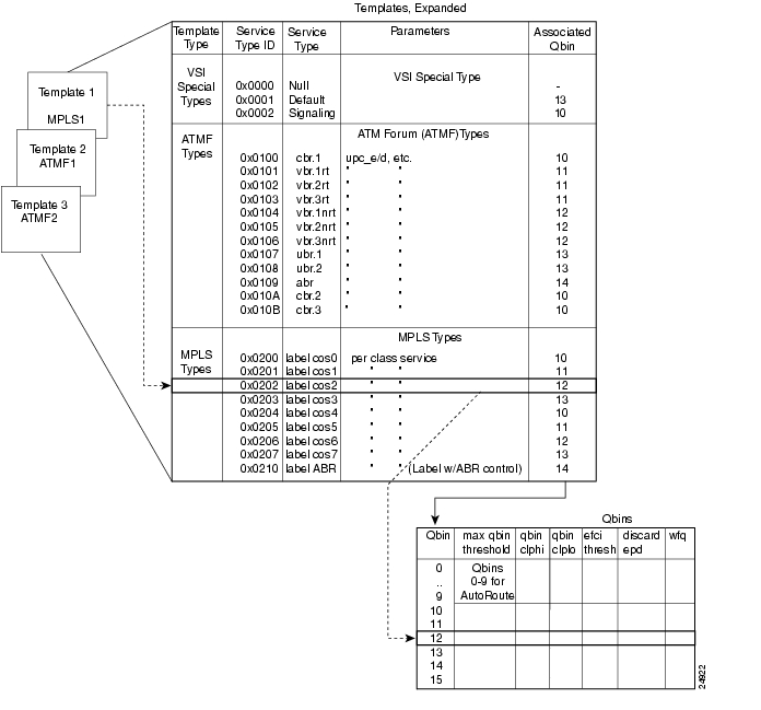
You can assign any one of the nine templates to a Virtual Switch Interface (see Figure 23-9).
Each template table row includes an entry that defines the Qbin to be used for that Class of Service. See Figure 23-9 for an illustration of how Service Class databases map to Qbins. This mapping defines a relationship between the template and the interface Qbin's configuration.
A Qbin template defines a default configuration for the set of Qbins for the logical interface. When a template assignment is made to an interface, the corresponding default Qbin configuration becomes the interface's Qbin configuration.
Some of the parameters of the interface's Qbin configuration can be changed on a per-interface basis. Such changes affect only that interface's Qbin configuration and no others, and do not affect the Qbin templates.
Figure 23-9 Service Template Overview
Qbin templates are used only with Qbins that are available to VSI partitions, specifically, Qbins 10 through 15. Qbins 10 through 15 are used by the VSI on interfaces configured as trunks or ports. The rest of the Qbins (0-9) are reserved for and configured by Automatic Routing Management.
Each template table row includes an entry that defines the Qbin to be used for that Class of Service. This mapping defines a relationship between the template and the interface Qbin's configuration. As a result, you need to define a default Qbin configuration to be associated with the template.
Note
Figure 23-10 Service Template and Associated Qbin Selection
Extended Service Types Support
The service-type parameter for a connection is specified in the connection bandwidth information parameter group. The service-type and service-category parameters determine the Service Class to be used from the service template.
Supported Service Categories
There are five major service categories and several subcategories. The major service categories are described in Table 23-7. A list of the supported service subcategories is shown in LCNs.
Table 23-7 Service Category Listing
CBR
0x0100
VBR-rt
0x0101
VBR-Nrt
0x0102
UBR
0x0103
ABR
0x0104
Supported Service Types
The service type identifier is a 32-bit number.
There are three service types:
•
•
•
The service type identifier appears on the dspsct screen when you specify a Service Class template number and service type; for example:
dspsct <2> <vbrrt1>A list of supported service templates and associated Qbins, and service types is described in Table 23-8.
VC Descriptors
A summary of the parameters associated with each of the service templates is provided in Table 23-9 through Table 23-12. Table 23-13 provides a description of these parameters and also the range of values that may be configured if the template does not assign an arbitrary value.
Table 23-9 lists the parameters associated with Default (0x0001) and Signaling (0x0002) service template categories.
Table 23-10 and Table 23-11 lists the parameters associated with the PNNI service templates.
The connection parameters and their default values for label switching service templates are listed in Table 23-12.
VC Descriptor Parameters
If not already preconfigured, the connection parameters list the range of values that may be configured as described in Table 23-13.
Every Service Class does not include all parameters. For example, a CBR service type have fewer parameters than an ABR service type.
Note
Qbin Dependencies
Qbin templates deal only with Qbins that are available to VSI partitions, namely 10 through 15. Qbins 10 through 15 are used by VSI on interfaces configured as trunks or ports. The rest of the Qbins are reserved and configured by Automatic Routing Management.
When you execute a dspsct command, it will give you the default service type, and the Qbin number.
The available Qbin parameters are listed in Table 23-14.
Notice that the Qbins available for VSI are restricted to Qbins 10 to 15 for that interface. All 32 possible virtual interfaces are provided with 16 Qbins.
Qbin Default Settings
The Qbin default settings are listed in Table 23-15. The Service Class Template default settings for Label Switch Controllers and PNNI controllers are listed in Table 23-16.
Note
.
Understanding MPLS VC Merge
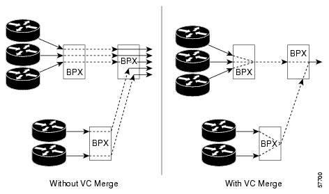
Virtual Circuit (VC) merge improves the scalability of MPLS networks and allows multiple incoming VCs to be merged into a single outgoing VC, which is called merged VC. Tag switching is supported. In the BPX 8600 series switch, VC Merge is implemented as part of the output buffering for ATM interfaces.
Note
Only frame-based connections are implemented. While preserving AAl5 framing, the key to VC Merge is to switch cells from the merging Label Virtual Circuit (LVC) to the merged LVC that points to the destination. An AAL5 frame consists of multiple cells. The cells from a particular frame must be in an uninterrupted sequence when it goes out after merging. Cells from one AAL5 frame cannot be intermingled with cells from another AAL5 frame on the same VC. Several AAL5 frames can arrive on different VCs and are merged onto a single VC without interleaving the frames.
VC Merge is responsible for processing any incoming VSI messages from the MPLS controller and identifies the merging request. VC-merge is enabled by filling at least 1023 VSI channels on any interface on the card. The Label Switch Controller (LSC) controls the limit of merged VCs you can have.
Both without VC Merge and with VC Merge examples are shown in Figure 23-11.
Figure 23-11 VC Merge Example
VC Merge Characteristics
The following are the characteristics of VC Merge:
•
•
•
•
•
•
•
•
•
•
Displaying Card Support for VC Merge
When adding y-redundancy (card redundancy) where one card supports VC Merge and the other card does not, a feature mismatch is declared with the following message displayed while executing the addyred command:
card pair is incompatible due to VC Merge support.If VC Merge is enabled on a card and that card is replaced with a card that does not support VC Merge, the dspcd screen shows the following message:
Front card must support VC MergeWhen you enter the dspcds command, the status of the card displays mismatch.
For parameter definitions that are used for the dspcd command, refer to the Cisco WAN Switching Command Reference, Release 9.3.30.
To display card support for VC Merge, use the following procedure.
Step 1
Last Command: dspcd <slot number>Step 2
The following example is a detailed card display summary:
m2 TN Cisco BPX 8620 9.3.a0 May 7 2001 21:32 GMTDetailed Card Display for BXM-155 in slot 4Status: ActiveRevision: HN04 Backcard InstalledSerial Number: 760313 Type: LM-BXMTop Asm Number: 28215802 Revision: BCQueue Size: 524280 Serial Number: A74072Support: 8 Pts, OC3, FST, VcShp Top Asm Number:Supp: VT,ChStLv 1,VSI(Lv 3,ITSMV) Supp: 8 Pts,OC3,SMF,RedSlot:NOSupp: APS(FW)Support: LMIv 1,ILMIv 1,NbrDisc,XLSupport: OAMLp, TrfcGen#Ch:32768,PG[1]:32736,PG[2]:32736PG[1]:1,2,3,4,PG[2]:5,6,7,8,#Sched_Ch:61440 #Total_Ch:61376Type: BXME, revision DXLast Command: dspcd 4Enabling VC Merge
To enable VC Merge, use the following procedure.
Note
Step 1
This Command: cnfcdparm <slot number><value><e|d>Step 2
Step 3
Step 4
The following example validates that VC Merge is enabled:
m2 TN Cisco BPX 8620 9.3.a0 May 7 2001 21:37 GMTCard Parameters1 Channel Statistics Level ......................................... 12 VC Merge State ......................................... ELast Command: cnfcdparm 5 2 eVC Merge enabled on this card.The channel statistics level is not related to the VC Merge state. For a description of all four channel statistics levels, see Chapter 5, "BXM Card Sets: T3/E3, 155, and 622."
If there is no acknowledgement and the BPX switch timed out, the following message will appear:
Card rejected cmd. VC Merge NOT enabled!For a description of VC Merge messages, see Table 23-17.
Disabling VC Merge
To disable VC Merge, use the following procedure.
Step 1
This Command: cnfcdparm <slot number><value><e|d>Step 2
Step 3
The following example appears:
m2 TN Cisco BPX 8620 9.3.a0 May 7 2001 21:47 GMTCard Parameters1 Channel Statistics Level ......................................... 12 VC Merge State ......................................... EThis Command: cnfcdparm 4 2'E' to Enable, 'D' to Disable [E]:Step 4
The following message appears as an acknowledgement:
Disabling VC Merge with active VSI partns on card may result in dropped conns
Continue?
Step 5
The following example validates that VC Merge is disabled:
TN Cisco BPX 8620 9.3.a0 May 01 2001 20:41 GMTCard Parameters1 Channel Statistics Level ......................................... 12 VC Merge State ......................................... DLast Command: cnfcdparm 5 2 DVC Merge disabled on this card.The channel statistics level is not related to the VC Merge state. For a description of all four channel statistics levels, see Chapter 5, "BXM Card Sets: T3/E3, 155, and 622."
If there is no acknowledgement and the BPX switch timed out, the following message appears:
Card rejected cmd. VC Merge NOT disabled!For a description of VC Merge messages, see Table 23-17.
Warning
The following message appears:
Disabling of last partn on slot has caused disabling of VC Merge.Interpreting the Messages
After using the cnfcdparm command to either enable or disable VC Merge, the messages that are displayed after execution are described in Table 23-17.
Displaying the Status of VC Merge
After VC Merge is either enabled or disabled, enter the dspcdparm command to view the current status of VC Merge:
Last Command: dspcdparm 5 2When the applicable slot number is selected, the Card Parameters summary appears to indicate whether VC Merge is enabled or disabled.
If the slot specified does not support VC Merge, N/A appears as the VC Merge State in the Card Parameters summary.
Summary of VSI Commands
The commands for VSI are listed in Table 23-18.
![]()
![]()
![]()
![]()
![]()
![]()
![]()
![]()
Posted: Tue May 10 21:21:48 PDT 2005
All contents are Copyright © 1992--2005 Cisco Systems, Inc. All rights reserved.
Important Notices and Privacy Statement.