|
|

Table Of Contents
BXM Card Sets: T3/E3, 155, and 622
Y-Cabling of SMF-622 Series Back Cards
Automatic Protection Switching Redundancy
Operation in Port (UNI/NNI) Mode
Summary of Circuitry Functions
Fault Management and Statistics
BXM Card Sets: T3/E3, 155, and 622
This chapter describes the physical BXM card sets, major circuit functions, and technical specifications.
Contents of this chapter include:
•
Automatic Protection Switching Redundancy
•
Overview: BXM Cards
A BXM card set, using Application Specific Integrated Circuit (ASIC) technology, provides high speed ATM connectivity, flexibility, and scalability. The card set is comprised of a front card that provides the processing, management, and switching of ATM traffic and a back card that provides the physical interface for the card set.
Each interface of a BXM card is configured for either:
•
•
An example of a BPX switch network provisioned with BXM-622 cards is shown in Figure 5-1.
Figure 5-1 A BPX Switch Network with BXM Cards
BXM cards are compliant with ATM Forum UNI 3.1 and Traffic Management 4.0 specifications including Available Bit Rate (ABR) VS/VD. These cards provide the capacity to meet the needs of emerging bandwidth driven applications.
The types of BXM cards are regular and enhanced. The enhanced BXM cards (also called BXM-E) improve upon the regular BXM cards by delivering more cost-effective ATM switching and traffic management and support a higher connection density on certain models. Throughout this document, BXM is used to denote either the regular BXM or BXM-E. Specific BXM-E models are denoted with suffix D, DX, E, or EX.
The BXM cards are designed to support the following service classes:
•
•
•
•
•
•
•
All software and administration firmware for the BXM card is downloadable from the BCC and is operated by the BXM on-board sub-system processor.
The following are the types of front and back cards used for the BXM card set:
•
•
•
Any of the twelve general purpose slots in a BPX are used for the BXM cards. The same back cards are used whether the BXM ports are configured as trunks or ports. Table 5-1 and Table 5-2 list the available front and back card options for the BXM-T3/E3, BXM-155, and BXM-622.
Note
BXM Capabilities
The following are the major features of the BXM cards:
•
–
•
(see Table 5-1).•
•
•
•
–
–
•
•
•
•
•
•
•
•
•
•
•
ATM Layer
•
•
•
•
•
–
–
–
–
–
–
•
•
•
•
•
•
Service Types
The BXM cards support the full range of ATM service types per ATM Forum TM 4.0.
CBR Service
•
•
–
–
VBR Service
•
•
–
–
–
•
ABR Service
•
•
–
–
–
–
Maximum queue depth
Reserved queue depth
Congestion threshold
•
Based on Explicit rate stamping/EFCI cell tagging and ingress rate monitoring per ITU-T I.371
–
–
–
UBR Service
•
•
Virtual Interfaces
•
•
–
–
–
–
Enhanced BXM
The Enhanced BXM (BXM-E) cards improve the current BXM cards by delivering even more cost-effective ATM switching and traffic management. The Enhanced BXM cards come in D, E, DX and EX versions, both including the following key feature enhancements:
•
–
–
ACP Processor memory is 64 MB and the flash memory is doubled to 4 MB on all Enhanced BXM cards to allow more headroom for feature addition and enhancement in the future.•
With a more powerful processor and more VC configuration memory in ATM cell switching subsystem, the EX and DX versions of Enhanced BXM cards meet the increasing demand for greater number of connections per interface. BXM-E cards support a greater number of connections per interface, which cost effectively translates into supporting a greater user density.
Both DX and EX versions have the same connection density, providing you with the ability to upgrade networks with the high connection density on trunk side, port side, or a combination of trunks and ports. You can smoothly upgrade BXM cards to BXM-E capabilities; see the Upgrade BXM to BXM-E Cards section of Appendix A, "Upgrade Information."
•
On regular BXM cards, the VI traffic shaping rate is limited to OC-12/n. For example, where n is an integer. On the Enhanced BXM cards, the VI traffic shaping rate is any desired shaping rate with a precision of 9-bit mantissa and 4-bit exponent.
•
On the current BXM cards, the ABR support is limited to connections with AAL5 traffic. These connections allow early packet discard to be applied to avoid queue congestion and thus maintain RM cell flow. The Enhanced BXM cards extend the ABR support to connections with non-AAL5 traffic also. The Enhanced BXM cards minimize the problem of RM cell discard when RM cells are injected into a congested VC by reserving room for 8 RM cells even when the VC begins to drop data cells. The RM cell reserve can be globally configured for VS/VD and nonVS/VD connections.
•
On the current BXM cards, the ForeSight ABR (Cisco's prestandard ABR implementation) support is limited to bidirectional connections only. The current BXM cards also support ATM Forum standard ABR for both bidirectional and unidirectional connections. The Enhanced BXM cards will extend the ForeSight ABR support to include unidirectional connections also.
•
The Enhanced BXM cards provide coupling between the port ABR segment with ATM Forum ABR algorithm and the network ABR segment with ForeSight ABR algorithm.
•
The Enhanced BXM card hardware supports VC merge to facilitate Label Switching with simple software upgrade. With VC merge, the Enhanced BXM cards allow the BPX to aggregate multiple incoming frame-based VCs with the same destination address into a single outgoing frame-based VC. Cells from different VCIs going to the same destination are transmitted to the same outgoing VC using multipoint-to-point connections.
Where VC merge occurs, several incoming labels indicated by VCIs are mapped to one single outgoing label. This sharing of labels reduces the total number of virtual circuits required for label switching. Without VC merge, each source-destination prefix pair consumes one label VC on each interface along the path. VC merge reduces the label space shortage by sharing labels for different flows with the same destination.
For a more detailed description, see Chapter 23, "Configuring BXM Virtual Switch Interface."
The Enhanced BXM cards include a feature that is enabled by future firmware and switch software, which is to separate frame discard CLP0 and frame discard CLP1 thresholds for each class-of-service (CoS) queue.The Enhanced BXM cards support separate frame discard CLP0 and frame discard CLP1 thresholds for each CoS queue. This feature enables preferential treatment for conforming traffic within CIR (frames with CLP=1 start-of-frame cell) compared to nonconforming traffic (frames with CLP=0 start-of-frame cell) when applying early packet discard (EPD).
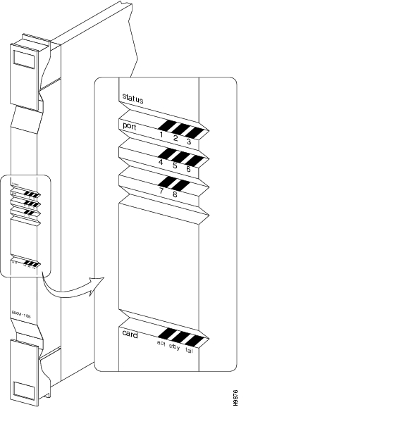
BXM Front Card Indicators
The BXM front panel has a three-section, multicolored "card" LED to indicate the card status. The card status LED is color-coded as described in Table 5-3. A three-section multi-colored "port" LED indicates the status of the ports.
Types of failures are indicated by various combinations of the card status indicators as described in Table 5-4.
A two-port BXM-622 is shown in Figure 5-2.
Figure 5-2 BXM-622 Front Panel, Two-Port Card Shown
An 8-port BXM-155 front card is shown in Figure 5-3.
Figure 5-3 BXM-155 Front Panel, Eight-Port Card Shown
A 12-port BXM-T3/E3 is shown in Figure 5-4.
Figure 5-4 BXM-T3/E3 Front Panel, 12-Port Card Shown
BXM Back card Connectors
The BXM back cards connect to the BXM front cards through the StrataBus midplane.
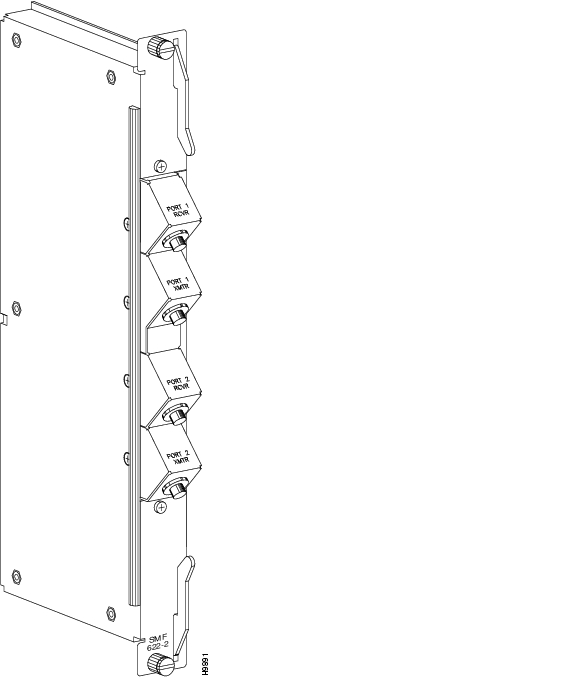
The BXM-622 is available in one or two port versions in either a single-mode fiber intermediate range (SMF) or a single-mode fiber long range (SMFLR) back card. Connector information is listed in Table 5-5. A 2-port SMF card is shown in Figure 5-5.
Figure 5-5 SMF-622-2, SMFLR-622-2, and SMFXLR-622-2 Back Card
Table 5-5 BXM-622 back cards
1 or 2
Two FC connectors per port, one each for the transmit and receive signal.
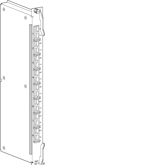
The BXM-155 is available in four or eight port versions in a choice of multimode fiber (MMF), single-mode fiber intermediate range (SMF), or single-mode fiber long range (SMFLR) back cards. Connector information is listed in Table 5-6 and an 8-port SMF card is shown in Figure 5-6.
Figure 5-6 BXM-155-8 Port back card, MMF, SMF, or SMFLR
Table 5-6 BXM-155 Back Cards
4 or 8
One SC connector per port, accommodates both the transmit and receive signals.
The BXM-STM1-EL4 is available in a four-port version that provides an electrical interface where the longer line lengths provided by the BXM optical back cards are not required.
Connector information is listed in Table 5-7.
Table 5-7 BXM-STM1-EL4 Back Card
4
Two SMB connectors per port, one each for the transmit and receive signals.
The back card is shown in Figure 5-7.
Figure 5-7 BPX-STM1-EL-4 Back Card
The BXM-T3/E3 is available in eight or twelve port versions.
Connector information is listed in Table 5-8.
Table 5-8 BXM-T3/E3 Back Cards
8 or 12
Two SMB connectors per port, one each for the transmit and receive signals.
A 12-port T3/E3 card is shown in Figure 5-8.
Figure 5-8 BPX-T3/E3 Back Card, 12-Port Option Shown
Y-Cabling of SMF-622 Series Back Cards
You can Y-cable the SMF-622 series back cards for redundancy by using the Y-Cable splitter shown in Figure 5-9. To configure the cards for Y-Cable redundancy, use the addyred command.
Figure 5-9 Y-Cabling of SMF-622 Series Back Cards
Automatic Protection Switching Redundancy
Automatic Protection Switching (APS) provides a standards-based line-redundancy for BXM OC-3 and OC-12 cards. The BXM OC-3 and BXM OC-12 cards support the SONET APS 1+1 and APS 1:1 standards for line redundancy. Line redundancy is provided by switching from the working line to the protection line.
The APS protocols supported by the BXM are listed in Table 5-9.
APS 1:1 redundancy provides line redundancy only and is supported with the standard BXM OC-3 and OC-12 front and back cards.
APS 1+1 redundancy provides both card and line redundancy. It uses the standard BXM OC-3 and OC-12 front cards, but uses a special APS Redundant Frame Assembly and APS Redundant back cards.
For SONET APS, card redundancy is provided by the use of two standard BXM front cards and two special back cards. The following are the special back cards:
•
•
•
•
•
•
•
•
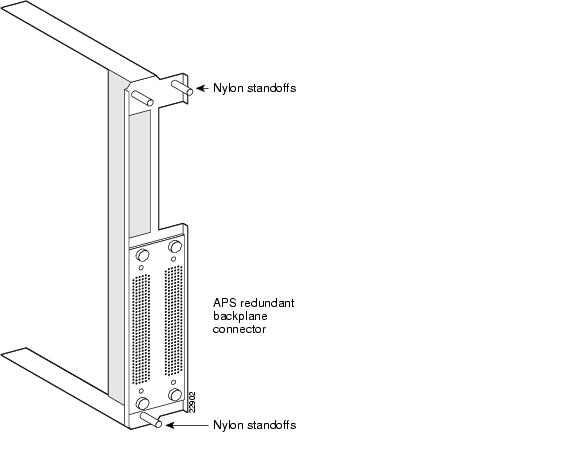
The two back cards are connected together by a BPX Redundant Backplane, which mates with the BPX Midplane. The connectors are the same as those for the standard back cards. An APS back card is shown in Figure 5-10. The BPX Redundant Backplane is shown in Figure 5-11.
A back card is shown in Figure 5-10. The APS Redundant Frame Assembly is shown in Figure 5-11. Two redundant back cards are connected together by the APS Redundant Frame Assembly. The APS Redundant Frame Assembly with associated APS redundant back cards is inserted as a unit in two appropriate back card slots.
For additional information, see Chapter 25, "Configuring SONET Automatic Protection System."
Figure 5-10 BXM SMF-155-8R Back Card
Figure 5-11 BXM APS Redundant Frame Assembly
BXM Functional Description
This functional description provides an overview of BXM operation.
Operation in Port (UNI/NNI) Mode
This section is an overview of operation when a BXM card port is configured in port (access) mode for connection to customer equipment.
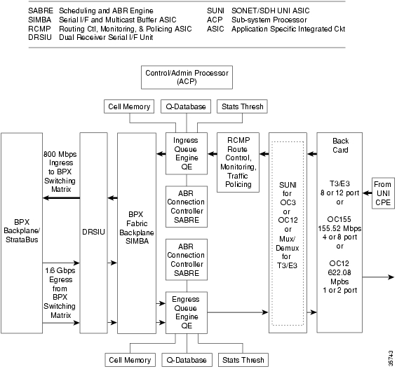
The ingress flow of ATM cells from CPE into a BXM port when the card is configured for port (access) operation is shown in Figure 5-12.
ATM cells from the customer premise equipment are:
•
•
•
•
For ABR cells, additional functions are performed by the SABRE ABR connection controller, which includes VS/VD, ForeSight, and virtual connection queueing.
Figure 5-12 BXM Access Port Ingress Operation
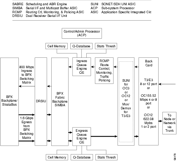
The egress flow of ATM cells out of the BXM when the card is configured for port (access) operation is shown in Figure 5-13.
ATM cells are:
1.
2.
3.
4.
5.
6.
For ABR cells, additional functions are performed by the SABRE ABR connection controller, which includes VS/VD, ForeSight, and virtual connection queueing.
Figure 5-13 BXM Port Egress Operation
Operation in Trunk Mode
This section is an overview of the operation of a BXM interface configured in the trunk mode for connection to another node.
The ingress flow of ATM cells into the BXM when the card is configured for trunk operation is shown in Figure 5-14.
On ingress, ATM cells from a trunk are:
1.
2.
3.
Figure 5-14 BXM Trunk Ingress Operation
The egress flow of ATM cells out of a BXM interface configured for trunk operation is shown in Figure 5-15.
On egress, ATM cells are:
1.
2.
3.
4.
5.
6.
Figure 5-15 BXM Trunk Egress Operation
Summary of Circuitry Functions
This section is a summary of the principal functions performed by the major functional circuits of the BXM.
DRSIU
The Dual Receiver Serial I/F Unit (DRSIU) provides a total egress capacity from the BPX switch fabric of 1.6 Gbps.
SONET/SDH UNI (SUNI)
The SUNI ASIC implements the BXM physical processing for OC-3 and OC-12 interfaces. SUNI provides SONET/SDH header processing, framing, ATM layer mapping, and processing functions for OC-12/STM-4 (622.08 Mbps) or OC-3/STM1 (155.52 Mbps).
For ingress traffic, the BXM physical interface:
1.
2.
3.
For egress traffic ATM cells are processed into SONET/SDH frames.
Alarms and statistics are collected at each level: section, line, and path.
Demultiplexing and Multiplexing
Demultiplexing, multiplexing, and associated circuits implement the BXM physical layer processing for T3/E3 interfaces, processing functions for T3 at a 44.736 Mbps rate, or E3 at a 34.368 rate.
The following are the functions for demultiplexing and multiplexing:
•
•
•
RCMP
Usage Parameter Control (UPC) is provided by the Routing Control, Monitoring, and Policing (RCMP) ASIC. Each arriving ATM cell header is processed and identified on a per VC basis. The policing function utilizes a leaky bucket algorithm.
In addition to UPC and traffic policing, the RCMP provides route monitoring and also terminates OAM flows to provide performance monitoring on an end-to-end per VC/VP basis.
Traffic policing and UPC functionality is in accordance with the Generic Cell Rate Algorithm (GCRA) as specified by ATM Forum's UNI 3.1 using dual leaky buckets.
•
–
–
•
–
–
In addition, two selective cell discard thresholds are supported for all queues for discard of CLP=1 cells should congestion occur.
SABRE
The Scheduling and ABR Engine (SABRE) includes both VS/VD and ForeSight dynamic traffic transfer rate control and other functions:
•
•
•
•
•
•
Ingress and Egress Queue Engines
The overall function of the queue engines is to manage the bandwidth of trunks or ports through management of the ingress and egress queues.
In addition to the ABR VS queues, the ingress queues include 15 slot servers, one for each of 14 possible BPX destination slots, plus 1 for multicast operation. Each of the 15 slot servers contains 16 Qbins, supporting 16 classes of service per slot server.
In addition to the ABR VS queues, the egress queues include 32 Virtual Interfaces (VIs). Each of the 32 VIs supports 16 Qbins.
SIMBA
The following are the components that are provided for the Serial Interface and Multicast Buffer ASIC (SIMBA):
•
•
•
•
•
ACP Subsystem Processor
The following are the ACP Subsystem processor localized functions:
•
•
•
•
•
Fault Management and Statistics
This section describes the specifications used for fault management and statistics.
Port Mode
Compliant to Bellcore GR-253-CORE
Alarms
•
•
•
•
•
•
•
Performance Monitoring
•
•
•
•
•
•
•
Statistics
•
The number of statistics that are collected on a VC depends on the Channel Stats Level, which is configured using the cnfcdparm command.•
•
OAM
•
•
•
Trunk Mode
Compliant to Bellcore GR-253-CORE
Alarms
•
•
•
•
•
•
•
Performance Monitoring
•
•
•
•
•
•
•
Statistics
Process Monitoring for ATM Header Cell Processing
•
•
Channel Statistics Level
The Channel Statistics Level of a BXM card defines the number of channel statistics that are collected on the card. The following are the four levels of channel statistics:
•
•
•
All BXM cards are preset at Channel Statistics Level 1 by default. Use the cnfcdparm command to change the Channel Statistics Level.
The BXM cards together with the number of supported connections for each Channel Statistics Level are listed in Table 5-10.
The supported channel statistics at each Statistics Level are listed in Table 5-11.
Technical Specifications
This section describes the technical specifications for the BXM card sets.
Physical Layer
•
•
–
–
•
–
–
•
•
•
General Information
•
•
•
•
•
•
•
•
–
–
![]()
![]()
![]()
![]()
![]()
![]()
![]()
![]()
Posted: Tue May 10 21:09:34 PDT 2005
All contents are Copyright © 1992--2005 Cisco Systems, Inc. All rights reserved.
Important Notices and Privacy Statement.