|
|

Table Of Contents
Configuring BXM Virtual Trunks
Typical ATM Hybrid Network with Virtual Trunks
Virtual Trunks Across a Public ATM Cloud
Handling VPC Failure Within the ATM Cloud
Virtual Trunk Transmit Queuing
General Procedures to Set Up Virtual Trunking
Setting up a Virtual Trunk through an ATM cloud
Virtual Trunk Across an ATM Network Example
Primary Configuration Commands
Virtual Trunk Commands Common to BXM and UXM
Virtual Trunk BXM/BNI Commands
Configuring BXM Virtual Trunks
This chapter describes the Broadband Switch Module (BXM) virtual trunks.
Contents of this chapter include:
•
Overview
•
•
Note
Overview
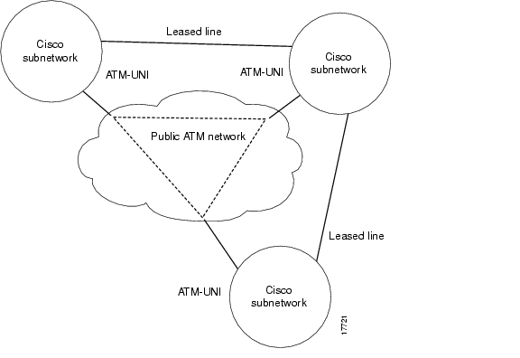
Virtual trunking provides connectivity for Cisco switches through a public ATM cloud as shown in Figure 24-1. Because a number of virtual trunks can be configured across a physical trunk interface, virtual trunks provide a cost effective means of connecting across a public ATM network. Each virtual trunk typically uses only part of a physical trunk's resources. Yet, like regular trunks, virtual trunks can carry high-priority traffic.
The hybrid network configuration provided by virtual trunking allows private virtual trunks to use the mesh capabilities of the public network in interconnecting the subnets of the private network.
A virtual trunk is simply "a trunk defined over a public ATM service." The trunk really does not exist as a physical line in the network. You use an additional level of reference, called a virtual trunk number, to differentiate the virtual trunks found within a physical port.
You establish connectivity through a public ATM cloud by allocating virtual trunks between the nodes on the edge of the cloud. With only a single trunk port attached to a single ATM port in the cloud, a node uses the virtual trunks to connect to multiple destination nodes on the other side of the cloud. From the perspective of a Cisco node, a virtual trunk is equivalent to a Virtual Path Connection (VPC) provided by the ATM cloud network, which provides connectivity through the cloud.
The ATM equipment in the cloud must support Virtual Path switching and moving incoming cells based on the VPI in the cell header. Within the cloud, one virtual trunk is equivalent to one VPC. Because the VPC is switched with just the VPI value, the 16 VCI bits (from the ATM cell format) of the ATM cell header are passed transparently through to the other end. The VCI bits within the header are passed transparently through the entire cloud (see Figure 24-1).
The BXM card physical trunk interface to the ATM cloud is a standard ATM UNI or NNI interface at the cloud access point. The administrator of the ATM cloud, for example, Service Provider specifies whether the interface is UNI or NNI, and also provides the VPI to be used by a virtual trunk across the cloud.
The following are the two general types of virtual trunks:
•
•
Typical ATM Hybrid Network with Virtual Trunks
With the BPX switch, you can set up virtual networks with either the Broadband Network Interface (BNI) card or with the BXM card. Virtual trunks can originate and terminate on:
•
or
•
or
•
•
BNIs to BXMs or UXMs.When the Cisco virtual trunk interface is a BXM interface accessing a port in the Public ATM network, the Public ATM port may be a UNI or NNI port on a BXM, ASI, or other standards-compliant UNI or NNI port.
When the Cisco virtual trunk interface is a BNI interface accessing a port in the Public ATM network, the Public ATM port must be a port on a BPX.
Figure 24-1 shows three Cisco WAN switching networks, each connected to a Public ATM Network through a physical interface. The Public ATM Network is shown linking all three of these subnetworks to every other one with a full meshed network of virtual trunks. In this example, each physical interface is configured with two virtual trunks.
Figure 24-1 Typical ATM Hybrid Network using Virtual Trunks
Benefits of Virtual Trunking
The following are the virtual trunking benefits:
•
•
VSI virtual trunks allow PNNI or MPLS services to be carried over part of a network that does not support PNNI or MPLS services. The part of the network that does not support PNNI or MPLS may be a public ATM network, or simply consist of switches that have not yet had PNNI or MPLS enabled.
•
•
•
•
How Virtual Trunking Works
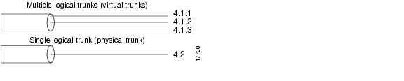
The following is the syntax to describe a virtual trunk:
slot.port.vtrunkThe virtual trunk parameters are described in Table 24-1.
In general, the maximum number of virtual trunks that is configured per card equals the number of virtual interfaces (VIs) provided by the card and how many are available for use. Each port, trunk or virtual trunk interface requires the use of one VI. For example, the BXM supports 31 virtual interfaces; therefore, up to a combination of 31 ports, trunks, and virtual trunks are configured on one BXM card.
Note
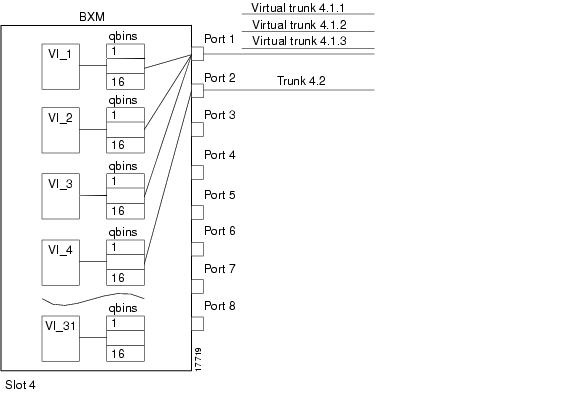
In Figure 24-2, three virtual trunks 4.1.1, 4.1.2, and 4.1.3 are shown configured on a physical trunk that connects to the port 4.1 interface of a BXM. Also, a single trunk is shown configured on port 4.2 of the BXM. In this example, four VIs are used, one each for virtual trunks 4.1, 4.2, and 4.3, and one for physical trunk 4.2.
Figure 24-2 Virtual and Physical Trunks on a BXM
Each logical trunk, either physical or virtual, is assigned a virtual interface when it is activated.
A BXM card has 31 possible egress virtual interfaces. Each of these interfaces in turn has 16 Qbins assigned to it.
In the example in Figure 24-3, port 1 has three virtual trunks (4.1.1, 4.1.2, and 4.1.3), each of which is automatically assigned a virtual interface (VI) with the VI's associated 16 Qbins. Port 2 is shown with a single physical trunk (4.2) and is assigned a single VI.
On a 1-port BXM-622 card, for example, up to 31 virtual interfaces can be used on the port corresponding to 31 virtual trunks. On an 8-port BXM 155 card, for example, the 31 VIs are distributed to the active trunks, standard, or virtual. If trunks were activated on all eight ports, the maximum number of VIs that can be assigned to one port is 24.(31 less 1 for each of the other 7 trunks activated on the card).
Figure 24-3 BXM Egress VIrtual Interfaces and Qbins
Automatic Routing Management connections use Qbins 0 through 9.
Virtual Switch Interfaces (VSIs), which support master controllers use Qbins 10 through 15, as applicable. The BXM can concurrently support MPLS and Automatic Routing Management, or PNNI and Automatic Routing Management, or MPLS and PNNI at the same time on a given VSI.
Virtual Trunks Across a Public ATM Cloud
An example of a number of virtual trunks configured across a Public ATM Network is shown in Figure 24-4. There are three virtual trunks shown across the network, each with its own unique VPC.
The three virtual trunks shown in the network are:
•
•
•
Each VPC defines a virtual trunk that supports the traffic types are described in Table 24-2.
Figure 24-4 Virtual Trunks across a Public ATM Network
Routing with Virtual Trunks
Automatic Routing Management, PNNI, and MPLS each use different routing mechanisms. However, the routing mechanisms meet the following criteria when dealing with virtual trunks:
•
•
•
The characteristics of a virtual trunk used by connection routing are maintained throughout the network. Virtual trunk existence, traffic classes, and connection channels are sent to every node to allow the routing algorithm to use the trunk correctly. Routing uses only those virtual trunks that can support the traffic type of the connection.
Handling VPC Failure Within the ATM Cloud
Any VPC within the ATM cloud generates a virtual trunk path failure in the Cisco network. This trunk failure allows applications (such as connection routing) to avoid the problem trunk. Upon receiving notification of the VPC failure, the trunk is placed into the "Communication Failure" state and the appropriate trunk alarms are generated. The trunk returns to the "Clear" state after the VPC failure clears and the trunk communication failure test passes.
The ATM cloud notifies the Cisco network of the VPC failures using an ILMI traps or F4 end-to-end AIS OAM flows. Prior to switch software Release 9.3.30, virtual trunk path failure could be detected only by the receipt of an ILMI trap. This was a limitation because many public ATM clouds use AIS OAM flows, instead of ILMI, to signal alarm conditions. As a result, virtual trunk path failure was often detected indirectly through a communication failure test, causing a substantial delay in rerouting connections or other corrective action. The current software provides the ability to detect F4 AIS flow on a BXM virtual trunk, which reduces the failure detection time by a factor of ten compared to the communication failure test.
The F4 AIS OAM cell detection enhancement is disabled by default. It can be enabled on a per trunk basis using the cnftrk command.For a detailed explanation of the cnftrk command and related commands refer to the Cisco WAN Switching Command Reference, Release 9.3.30.
Note
Connection Management
The cell addressing method for connections routed through a virtual trunk handles multiple types of traffic flowing through an ATM cloud. The header format of cells can match the ATM-UNI or ATM-NNI format because the port interface to the ATM cloud is a physical interface configured as either a UNI or NNI interface, as specified by the administrator of the ATM cloud.
Cell Header Formats
Cells transmitted to a virtual trunk use the standard UNI or NNI cell format.
Before cells enter the cloud on a virtual trunk, the cell header is translated to a user configured VPI value for the trunk, and a software configured VCI value, which is unique for the cell. The trunk card at the edge of the cloud ensures that cells destined for a cloud VPC have the correct VPI/VCI.
As cells are received from the cloud by the BPX or IGX in the Cisco networks at the other end of the cloud, these VPI/VCIs are mapped back to the appropriate VPI/VCI addresses by the Cisco nodes for forwarding to the next destination.
The VPI is an 12-bit value ranging from 1 to 4095. The VCI is a 16-bit value ranging from 1 to 65535.
The VPI value across the virtual trunk is identical for all cells on a single virtual trunk. The VCI value in these cells determines the final destinations of the cells. On BNI cards, virtual trunking is a modified ATM UNI cell format (Strata-UNI) that stores the ForeSight information, as applicable, in the header of a Strata-UNI cell format. A virtual trunk with a BNI at one end must terminate on a BNI at the other end.
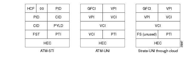
Figure 24-5 shows three different cell header types: ATM-STI, ATM-UNI, and Strata-UNI through a cloud. The ATM-NNI header which is not shown, differs in format from the ATM-UNI only in that there is no Generic Flow Control Interface (GFCI) field and those four bits are added to the VPI bits to give a 12-bit VPI.
The ATM-STI header is used with BNI trunks between BPX nodes within a Cisco switch subnetwork. The ATM-UNI is the standard ATM Forum UNI supported by the BXM card along with standard NNI. Virtual trunks terminating on BXMs or UXMs use the standard ATM-UNI or ATM-NNI header as specified by the cloud administrator, for example, a service provider. Virtual trunks terminating on BNIs use the Strata-UNI header.
Because the BNI cards use a Strata-UNI format across a virtual trunk, BNI virtual trunks are not compatible with BXM/UXM virtual trunks, which use either the standard UNI or NNI cell header formats. Therefore, BXM to BXM, UXM to UXM, and BXM to UXM virtual trunks are supported; however, BNI to BXM or BNI to UXM virtual trunks are not supported.
Figure 24-5 ATM Virtual Trunk Header Types
Bit Shifting for Virtual Trunks
The ATM-STI header uses four of the VCI bit spaces for additional control information. When the cell is to be transferred across a public network, a shift of these bit spaces is performed to restore them to their normal location so they are used across a network expecting a standard header.
For detailed information on how to configure bit shifting, see the General Procedures to Set Up Virtual Trunking section.
Virtual Trunk Bandwidth
The total bandwidth of all the virtual trunks in one port cannot exceed the maximum bandwidth of the port. The trunk loading (load units) is maintained per virtual trunk, but the cumulative loading of all virtual trunks on a port is restricted by the transmit and receive rates for the port.
Virtual Trunk Connection Channels
The total number of connection channels of all the virtual trunks in one port cannot exceed the maximum number of connection channels of the card. The number of channels available is maintained per virtual trunk.
Cell Transmit Address Translation
All cells transmitted to a virtual trunk have a translated cell address. This address consists of a VPI chosen by the user and a VCI (ConId) chosen internally by the software. The trunk firmware is configured by the software to perform this translation.
Cell Receive Address Lookup
The user-chosen VPI is the same for all cells on a virtual trunk.
At the receiving end, multiple virtual trunks can send cells to one port. The port must be able to determine the correct channel for each of these cells.
The VPI is unique on each trunk for all the cells, but the VCI may be the same across the trunks. Each port type has a different way of handling the incoming cell addresses. Only the BXM and UXM are discussed here.
Selection of Connection Identifier
For connections, the associated connection are selected from a pool of connection for the entire card. Each virtual trunk can use the full range of acceptable conid values. The range consists of all the 16-bit values (1 to 65535) excluding the node numbers and blind addresses. A port uses the VPI to differentiate connections that have the same conid.
You can change the number of channels per virtual trunk once the trunk has been added to the network. Decreasing the number of channels on an added virtual trunk causes connection reroutes; whereas, increasing the number of channels on an added virtual trunk will NOT cause connection reroutes.
Routing VPCs over Virtual Trunks
A VPC is not allowed to be routed over a virtual trunk. The routing algorithm excludes all virtual trunks from the routing topology. The reason for this restriction is due to how the virtual trunk is defined within the ATM cloud.
The cloud uses a VPC to represent the virtual trunk. Routing an external VPC across a virtual trunk would consist of routing one VPC over another VPC. This use of VPCs is contrary to its standard definition. A VPC should contain multiple VCCs, not another VPC. To avoid any nonstandard configuration or use of the ATM cloud, VPCs cannot be routed over a virtual trunk through the ATM cloud.
VPC Configuration with the ATM Cloud
In order for the virtual trunk to successfully move data through an ATM cloud, the cloud must provide some form of connectivity between the trunk endpoints. The ATM equipment in the cloud must support virtual path switching and move incoming cells based on the VPI in the cell header.
A virtual path connection (VPC) is configured in the cloud to join two endpoints. The VPC can support either CBR, VBR, or ABR traffic. A unique VP ID per VPC is used to moved data from one endpoint to the other. The BPX nodes at the edge of the cloud send in cells that match the VPCs VPI value. As a result, the cells are switched from one end to the other of the ATM public cloud.
Within the ATM cloud one virtual trunk is equivalent to one VPC. Since the VPC is switched with just the VPI value, 16 VCI bits (from the ATM cell format) of the ATM cell header are passed transparently through to the other end.
If the public ATM cloud consists of BPX nodes using BXM cards, the access points within the cloud are BXM ports. If the cloud consists of IGX nodes, the access points within the cloud are UXM ports.
Virtual Trunk Interfaces
The two ends of a virtual trunk can have different types of port interfaces. For example, a virtual trunk contains a T3 port at one end of the ATM cloud and an OC-3 port at the other end.
However, both ends of the trunk must have the same bandwidth, connection channels, cell format, and traffic classes. This requirement is automatically checked during the addition of the trunk.
Virtual Trunk Traffic Classes
All types of traffic from a private network using Cisco nodes are supported through a public ATM cloud. The CBR, VBR, and ABR configured virtual trunks within the cloud should be configured to carry the following correct types of traffic.
•
•
•
A CBR configured trunk is best suited to carry delay sensitive traffic such as voice/data, streaming video, and ATM CBR traffic, and so on.
A VBR configured trunk is best suited to carry frame relay and VBR traffic, and so on.
An ABR configured trunk is best suited to carry ForeSight and ABR traffic, and so on.
Two-stage queueing at the egress of BXM virtual trunks to the ATM cloud allows shaping of traffic before it enters the cloud. However, the traffic is still routed on a single VPC in the cloud and may be affected by the traffic class of the VPC selected.
You can configure any number of virtual trunks up to the maximum number of virtual trunks per slot (card) and the maximum number of logical trunks per node. These trunks can be any of the three trunk types: CBR, VBR, or ABR.
You can configure any number of virtual trunks between two ports up to the maximum number of virtual trunks per slot and the maximum number of logical trunks per node. These trunks can be any of the three trunk types.
Virtual Trunk Transmit Queuing
In the BXM, the egress cell traffic out of a port is queued in the following two stages:
•
•
In other words, the types of traffic are queued separately as described in Table 24-2.
These classes are all queued separately, and the overall queue depth of the virtual interface is the sum of all the queue depths shared by all the available queues. Because each virtual trunk occupies one virtual interface (VI), the overall queue depth available for the virtual trunk is that of its VI.
You do not configure the VI directly.
You use the cnftrkparm command to configure the queues within Automatic Routing Management virtual trunks.
You use the cnfvsiif and cnfqbin commands to configure the queues within VSI virtual trunk VIs.
General Procedures to Set Up Virtual Trunking
This section describes the general procedures to set up virtual trunking.
Setting up the ATM Cloud
To set up the ATM cloud for supporting Virtual Trunks using Cisco equipment, for example, a BPX or IGX cloud, use the following procedure as an example:
Step 1
Step 2
upln slot.port
addport slot.port
upport slot.port
cnfport slot.port, and set the shift parameter accordingly as described below.
If the ATM cloud network has BNI cards or if the VPC can route over BNI trunks in the ATM cloud, set the Shift parameter to "H" (Shift on HCF); otherwise, set it to "N".
The Shift/No shift parameter specifies whether or not the VCI bits in the cell header should be shifted based on the HCF field of the cell header on cells arriving from the backplane. It is how Cisco networks convert STI cells to standards based cell formats, and similarly how standards-based cell formats are converted back to STI cells.
Step 3
This command: addcon joker 5.1.1.* swstorm 6.2.10.*In the cloud network, add a virtual path connection for each end of the virtual trunk that is to be routed through the cloud.
For example, 5.1 and 6.2 are ports that are hooked up and configured for virtual trunking. DACS connections are acceptable.
Note
Table 24-3 VPI Ranges
BXM/UXM (UNI)
1 to 255
BXM/UXM (NNI)
1 to 4095
BNI T3/E3
1 to 255
BNI OC-3
1 to 63
The CBR/VBR parameter must also correspond to the virtual trunk type of the virtual trunk. For T3, set PCR to 96000 and CDTV to 24000 for the connection so that the does not drop cells. Cisco recommends these values based on testing.
Setting up a Virtual Trunk through an ATM cloud
To set up the BPX private network for virtual trunking, use the following procedure as an example.
Step 1
Step 2
Enter the uptrk command to enable the virtual trunk on the BXM trunk interface as follows:
This command: uptrk <slot>.<port>.<vtrk>Enter the cnftrk command as follows:
This command:cnftrk <slot>.<port>.<vtrk>If the cloud is already configured, the alarm on the virtual trunk should clear.
Set the Shift parameter to "N", and also make sure the Virtual Trunk configuration matches with the VPC configuration as described in Step 1.
Step 3
Step 4
This command: addtrk <slot>.<port>.<vtrk>The vtrk parameter can be 1 to 31 for BXM virtual trunks.
Note
For example, a virtual trunk supported by a BXM-T3 interface on one end can be supported by a UXM OC-3 interface on the other end.
However, both ends of the trunk must have the same:
•
•
•
•
The addtrk command verifies this when you add the trunk.
Virtual Trunk Across an ATM Network Example
The procedure in this section gives the specific commands for every step in adding one virtual trunk across an ATM network. This is a very typical situation.
This procedures assumes this hypothetical situation:
•
•
•
Figure 24-6 Addition of Virtual Trunks Across a Public ATM Network
Given this situation, you perform the following steps:
The VPI values you choose by using the cnftrk command must match those used by the cloud VPC.
In addition, both ends of the virtual trunk must match with respect to:
•
•
•
•
Use the addtrk command to check for matching values before allowing the trunk to be added to the network topology.
The network topology as seen from a dsptrks command at BPX_A would be:
BPX_A 4.3.1-10.2.1/IGX_A
BPX_A 4.3.2-5.1.1/BPX_B
Command Overview
The commands summarized are specific to virtual trunk usage on the BPX, using the BXM cards. For complete information about each these commands, refer to the Cisco WAN Switching Command Reference and Cisco WAN Switch SuperUser Command Reference.
For information about the UXM, refer to the IGX 8400 Series documents. Also, refer to the Cisco WAN Manager documents for application information using a graphical user interface for implementing command functions.
Primary Configuration Commands
The primary commands used for configuration of virtual trunks are described in Table 24-4.
APS Redundancy
Virtual trunks support APS redundancy on BXM OC-3 and OC-12 ports. For more information, see Chapter 25, "Configuring SONET Automatic Protection System." To configure APS redundancy, use the following commands:
•
•
•
•
The prior Y-redundancy is not supported by virtual trunks.
Virtual Trunk Commands
Because a virtual trunk is defined within a trunk physical interface, the physical characteristics are derived form the interface. All the virtual trunks within a port have the same attributes.
If a physical trunk is specified on a physical port that supports multiple virtual trunks, the command is applied to all virtual trunks on the physical port.
If a virtual trunk is specified for a command that configures information related to the physical port, the physical port information is configured for all virtual trunks.
Virtual Trunk Commands Common to BXM and UXM
The entries in Table 24-5 that are marked with a [*} are configured on a logical trunk basis, but automatically affect all trunks on the port when a physical option is changed. For example, if the line framing is changed on a virtual trunk, all virtual trunks on the port are automatically updated to have the modified framing.
The virtual trunk commands are available on both the IGX and the BPX and have the same results
(see Table 24-5). For more information on the IGX and UXM, refer to the IGX documentation.
Virtual Trunk UXM Commands
The commands listed in Table 24-6 are IGX (UXM) specific, or behave differently than their BPX counterparts. For further information about UXM virtual trunk commands, refer to the IGX 8400 Series documentation.
Virtual Trunk BXM/BNI Commands
The BPX-specific commands are listed in Table 24-7.
![]()
![]()
![]()
![]()
![]()
![]()
![]()
![]()
Posted: Tue May 10 21:20:39 PDT 2005
All contents are Copyright © 1992--2005 Cisco Systems, Inc. All rights reserved.
Important Notices and Privacy Statement.