|
|

Table Of Contents
BPX Switch Common Core Components
Line Module for the Alarm/Status Monitor Card
BPX Switch StrataBus 9.6 and 19.2 Gbps Backplanes
BPX Switch Common Core Components
This chapter describes the common core hardware components for the BPX switch.
Contents of this chapter include:
•
BPX Switch StrataBus 9.6 and 19.2 Gbps Backplanes
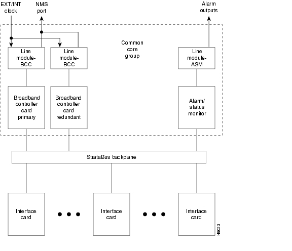
The BPX switch Common Core group includes the components shown in Figure 3-1:
•
–
–
Note
•
•
The BCC-4V provides a 16 x 32 crosspoint switch architecture to extend the BPX peak switching capability from 9.6 up to 19.2 Gbps peak. The BCC-4V also provides 4 MBytes of BRAM and 128 MBytes of DRAM.
The following are the functions of the common core components shown in Figure 3-1:
•
•
•
•
•
•
Broadband Controller Card
The Broadband Controller Card (BCC) is a microprocessor-based system controller, which is used to control the overall operation of the BPX switch. The controller card is a front card that is usually equipped as a redundant pair.
Slots number 7 and number 8 are reserved for the primary and secondary (standby) broadband controller cards. Each broadband controller front card requires a corresponding back card.
For nonredundant nodes, a single BCC is used in front slot number 7 with its appropriate back card.
For redundant nodes, a pair of BCCs of matching type, are used in front slot numbers 7 and 8.
Note
Figure 3-1 Common Core Group Block Diagram
The term BCC refers to the functional operation of the Broadband Controller Card. When a difference in operation does occur, the specific type of BCC is specified.
The BCC-4V provides a 16 x 32 cross-point architecture that increases the peak switching capacity of the BPX switch to 19.2 Gbps, with a sustained nonblocking throughput of 9.6 Gbps.
For information to operate the BPX at 19.2 Gbps with the BCC-4V and to program the NOVRAM, see the Verifying 9.6 or 19.2 Gbps Backplane section of Chapter 13, "Installing the BPX Switch Cards."
Features
The Broadband Controller Card performs the following major system functions:
•
•
•
•
•
•
•
The BCC-3-BC provides the physical interface for the BCC-3-32M, BCC-3-64M, and BCC-4V.The following are the features for the Broadband Controller Card:
•
•
•
•
•
•
•
•
•
•
Functional Description
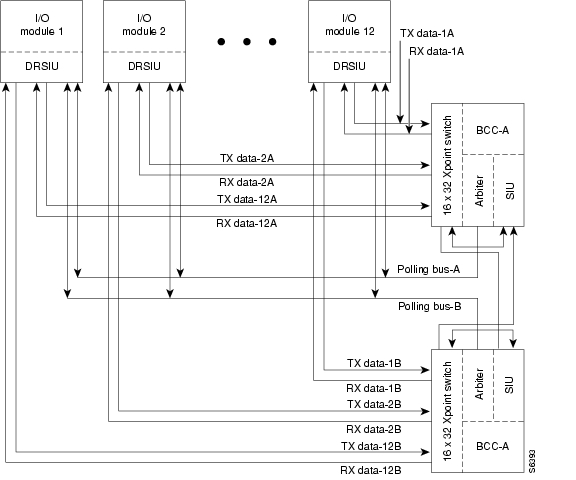
The BPX switch is a space switch, which employs a crosspoint switch for individual data lines to and from each port. The switching fabric in each BPX switch consists of three elements for the BCCs (see Figure 3-2):
•
•
–
•
The arbiter polls each card to see if it has data to transmit. It then configures the crosspoint switching matrix to make the connection between the two cards. Each connection is unidirectional and has a capacity of 800 Mbps (616.7 Mbps for cell traffic plus the frame overhead).
Only one connection at a time is allowed to an individual card.
Each card contains a Switch Interface Module (SIM), which provides a standardized interface between the card and the data lines and polling buses. The SIM responds to queries from the BCC indicating whether it has data ready to transmit.
With the BPX switch equipped with two BCCs, the cell switching is completely redundant in that there are always two arbiters, two crosspoint switches, two completely independent data buses, and two independent polling buses.
The BCC incorporates nonvolatile flash EEPROM, which permits new software releases to be downloaded over the network and battery-backup RAM (BRAM) for storing user system configuration data. The memory features maintain system software and configuration data even during power failures, eliminating the need to download software or reconfigure after the power returns.
The BPX switch cell switching is not synchronized to any external clocks; it runs at its own rate. No switch fabric clocks are used to derive synchronization nor are these signals synchronized to any external sources.
Node clocking is generated by the BCC. Because the BPX switch resides as an element in a telecommunications network, it is capable of synchronizing to higher-stratum clocking devices in the network and providing synchronization to lower stratum devices. The BCC can be synchronized to any one of three different sources under software control:
•
•
•
The BCC clock circuits provide clocking signals to every other card slot. If a function card needs to synchronize its physical interface to the BPX switch clock, it can use this timing signal to derive the proper reference frequency. These reference frequencies include DS1, E1, DS3, and E3.
Figure 3-2 BCC-4V Block Diagram
Front Panel Description
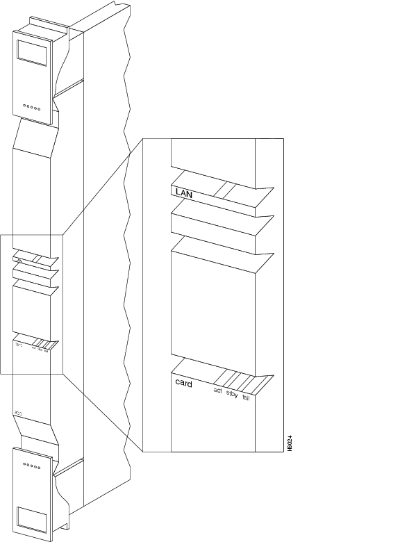
The BCC front panel has four Led, three card status LEDs, and a LAN LED (see Figure 3-3 and Table 3-1).
Figure 3-3 BCC Front Panel
The BCC runs self-tests continuously on internal functions in the background and if a failure is detected, the fail LED is lighted. If the BCC is configured as a redundant pair, the off-line BCC is indicated by the lighted stby LED. The stby LED also flashes when a software download or standby update is in progress. The LAN LED indicates activity on the Ethernet port.
Back Cards for the BCC-4V
The back cards for the BCC serve as an interface between the BPX switch and the BPX switch network management system.
For the BCC-4V, the back card is the BCC-3-BC. (These back cards are also known as the BCC back cards).
The BCC-4V provides important features such as support for up to 19.2 Mbps peak operation with BXM cards. Both BCCs in a node should be of the same type.
The back card provides the following interfaces:
•
•
•
•
The face plate connectors are described in Table 3-2, Table 3-3, and shown in Figure 3-4. The BCC15-BC is shown on the left and the BCC-3-BCC is shown on the right.
For specifications on cabling, see "BPX Switch Cabling Summary."
Figure 3-4 BCC15-BC and BCC-3-BC Back Card Face Plate Connectors
Another function of the line module back card is to provide the following two low-speed, serial communications ports as described in Table 3-3:
•
•
The Cisco WAN Manager NMS is connected to the LAN port on the BCC back cards. When control is provided through an Ethernet interface, you configure the node IP address by using the cnflan command for the BPX switch. For redundancy, also configure the LAN ports on both BCC back cards, each connected to an AUI adapter.
The LAN port of the primary BCC is active. If the secondary BCC becomes primary (active), then its LAN port becomes active. The Cisco WAN Manager workstation will automatically try to restore communications over the LAN and interfaces with the newly active BCC.
For small networks, one Cisco WAN Manager workstation is adequate to collect statistics and provide network management. For larger networks, additional Cisco WAN Manager workstations is required. For more information, refer to the Cisco WAN Manager User's Guide.
Alarm/Status Monitor Card
The Alarm/Status Monitor (ASM) card is a front card. Only one is required per node and it is installed in slot 15 of the BPX switch. It is used in conjunction with an associated back card, the Line Module for the ASM (LM-ASM) card.
The ASM and LM-ASM cards are noncritical cards used for monitoring the operation of the node and not directly involved in system operation. Therefore, there is no provision or requirement for card redundancy.
Features
The ASM card provides a number of the following support functions for the BPX switch:
•
•
•
•
•
Functional Description
BPX switch system software commands the ASM card to activate the major and minor alarm indicators and relays.
The following are the four significant circuits controlled by the ASM processor:
•
•
•
•
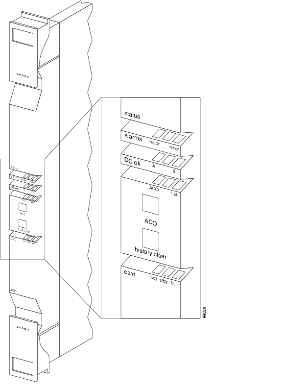
Front Panel Description
The front panel displays the status of the node and any major or minor alarms that might be present. Figure 3-5 illustrates the front panel of the ASM card. Each front panel feature is described in Table 3-4.
Figure 3-5 ASM Front Panel Controls and Indicators
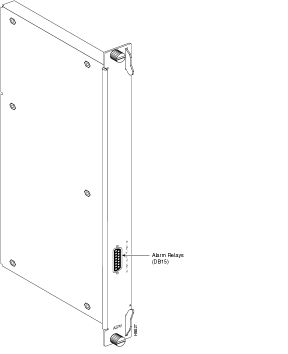
Line Module for the Alarm/Status Monitor Card
The Line Module for the Alarm/Status Monitor Card (LM-ASM) is a back card to the ASM card. It provides a simple connector panel for interfacing to your alarm system. It is not required for system and ASM operation.
The LM-ASM back card must be installed in back slot number 15.
Figure 3-6 illustrates the face plate of the LM-ASM which contains a single subminiature connector
(see Table 3-5). The Alarm Relay connector provides dry-closure (no voltage) relay contact outputs.
Table 3-5 LM-ASM Face Plate Connectors
1
ALARM RELAYS
A DB15 connector for alarm relay outputs. For more information about the pinouts, see "BPX Switch Cabling Summary."
Figure 3-6 LMI-ASM Face Plate
BPX Switch StrataBus 9.6 and 19.2 Gbps Backplanes
The BPX switch is equipped with a backplane that supports either a 9.6 or up to 19.2 Gbps operation. The 19.2 Gbps backplane can physically be identified by the card slot fuses on the bottom rear of the backplane. All BPX switch modules are interconnected by the BPX switch StrataBus backplane physically located between the front card slots and the back card slots.
Although the ATM data paths between the switching fabric and the interface modules are individual data connections, there are also a number of system bus paths for controlling the operation of the BPX switch. The StrataBus backplane, in addition to the 15 card connectors, contains the following signal paths:
•
•
•
•
•
All StrataBus wiring is completely duplicated and the two sets of bus wiring operate independently to provide complete redundancy. Either the A-side wiring or B-side wiring is enabled at any particular time by signals on the Control bus.
![]()
![]()
![]()
![]()
![]()
![]()
![]()
![]()
Posted: Tue May 10 21:06:26 PDT 2005
All contents are Copyright © 1992--2005 Cisco Systems, Inc. All rights reserved.
Important Notices and Privacy Statement.