|
|

This chapter describes the replacement of major BPX switch components:
After an alarm occurs, use the BPX switch software to isolate the problem. If an BPX switch part has failed, then it must be replaced. For information on alarms, see Chapter 28, Alarms and Statistics. For general procedures dealing with problems, see Chapter 29, Troubleshooting.
 |
Caution Only authorized personnel should remove and replace parts on the BPX switch system. |
Parts should be replaced only by qualified personnel who have taken the Cisco training courses or been trained by a qualified system manager. For assistance in diagnosing or replacing a failed part, call Cisco Customer Service.
When replacing a part, save the electrostatic bag, foam, and carton that the new part comes in. These packaging materials are needed for returning the failed part to Cisco. Contact Customer Service for information on returning parts.
The BPX switch front cards are:
|
Caution Ground yourself before handling BPX switch cards by placing a wrist strap on your wrist and clipping the wrist strap lead to the cabinet. |
When a card has failed, the red FAIL indicator for that card turns on. Before replacing it, check to see if the card needs only to be reseated. After reseating the card, wait for it to run its self-tests to see if the ACTIVE light comes on. If the card is seated correctly, but the FAIL light is still on, replace the card.
To remove a front cards:
Step 2 Check the status of the card by using the dspcd or dspcds commands. It should be failed or standby if the node is actively carrying traffic.
Step 3 If an active BNI card must be replaced, "down" it first by using the dncd command. Removing an active card affects operation only slightly if there is a standby card.
Step 4 If a BCC has failed, the other BCC will switch from standby mode to active. Use the dspcd command to verify that the standby BCC has entered the active mode. Then you can remove the failed BCC.
|
Caution Never remove the active BCC until the standby BCC has entered the "active" mode. Using the dspcd command is the only reliable way to determine that the standby BCC has finished updating and has entered the "active" mode. |
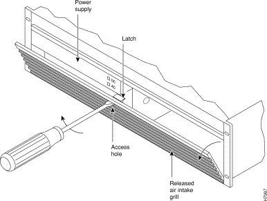
Step 5 Unlatch the Air Intake Grille. Locate the small access hole in the top, center of the Air Intake Grille.
Step 6 Fully insert a medium, flat-bladed screwdriver in the access hole.
Step 7 Rotate the screwdriver to release the spring latch holding the grille.
(Figure 30-1). The top of the grille should pop out.
Step 8 Tilt the grille forward to approximately a 45\xb0 angle.
Step 9 Put on a wrist strap to discharge any static.
Step 10 Rotate the top and bottom card extractors on the front of the card.
Step 11 Hold the card at the top and bottom and gently slide it out of the slot.
To install a front card in the BPX switch:
Step 2 Remove the replacement card from the antistatic shipping container.
Step 3 Hold the replacement card at top and bottom and gently insert it over the guides, and slide it all the way to the rear of the cabinet.
 |
Note The card should slide in easily with a light sliding friction from the EMI gaskets on adjacent cards. If it does not, check to see if there is anything restricting it—do not use excessive force. |
Step 4 Rotate the top and bottom latches on the card and push the card into the rear connector. You will feel the card seat itself as you push it in.
Step 5 Press firmly on the top and bottom extractors to complete the card seating process. The extractor should snap back to a vertical position after the card is properly seated.
Step 6 Replace the air intake grille by swinging it up and pressing in at the top until the latch snaps into place.
|
Caution Removing an active, single back card disrupts service on the node. |
To remove a line module:
Step 2 If an active card needs to be replaced, "down" it first with the dncd command. Removing an active card affects operation only slightly if there is a standby card.
Step 3 Before removing a LM-BCC, make sure the standby BCC stby indicator is on steady. A flashing stby indicator indicates it is in the process of downloading either configuration data or software and is not ready to accept a transfer.
Step 4 For a single card configuration, disconnect the cables from the back card face plate. Make a note of the location of each cable so that it can be replaced correctly.
Step 5 For a redundant card configuration, disconnect the appropriate leg of the Y-cable connecting to the back card to be replaced. DO NOT REMOVE THE OTHER LEG GOING TO THE BACKUP CARD.
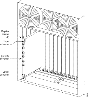
Step 6 Loosen the two captive screws on the back card faceplate and, pulling on the top and bottom card extractors, slide the card straight out of the shelf slot. (See Figure 30-2.)
To install a line module:
Step 2 Tighten the two captive screws. Tighten securely, but do not overtighten.
Step 3 Reconnect the T3 trunk cables to the LM-3T3 connectors from which they were disconnected.
Step 4 Perform the appropriate steps to bring the lines that were disconnected back on line.
DC Power Entry Modules (PEMs) contain few active components so they should rarely need replacement. Access is from the back of the node.
To remove a PEM:
Step 2 Turn off the primary source of power to the PEM to be replaced.
Step 3 Turn off the circuit breaker on the PEM to be replaced.
Step 4 Remove the two screws holding the conduit box cover (see Figure 30-3). Or, remove the plastic cover plate over the input terminal block.
Step 5 Remove the power input wiring at the PEM terminal block.
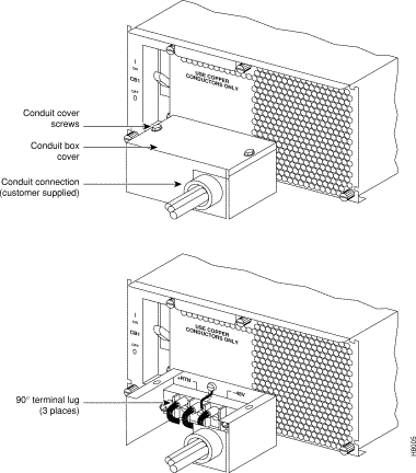
Step 6 If a conduit box is used, remove it. Remove the ground screw above the middle terminal block connector (see Figure 30-3).
Step 7 Remove the two standoffs on each side of the terminal block and pull the conduit box straight back. Set it aside. Do not try to remove the terminal block.
Step 8 Loosen the two captive screws (at the bottom corners) holding the PEM. Loosen the two connector jackscrews adjacent to the finger pull.
Step 9 Grasp the finger pull lip at the top of the PEM and pull the unit straight out.
Step 10 Replacement is the reverse of removal.
BPX switches are powered by redundant power supplies; either power supply can supply the current requirements of the node. The AC Power Supply is part of an assembly which is replaced as a single unit. Access to the AC Power Supply assembly is from the front, but first, the Air Intake Grille must be removed.
Step 2 Remove the Air Intake Grille. Locate the small access hole in the top, center of the Air Intake Grille.
Step 3 Fully insert a flat-bladed screwdriver (with a 1/4 in. blade) in the access hole.
Step 4 Rotate the screwdriver to release the spring latch holding the Air Intake Grille
(see Figure 30-4). The grille should pop out.
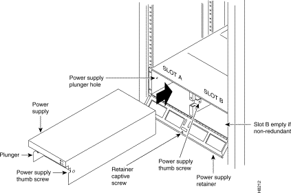
Step 5 Tilt the grille forward approximately a 45\xb0 angle, then lift if out and set it aside. This exposes the power supply retainer bracket.
Step 6 With a flat-bladed screwdriver, loosen the retainer bracket hold-down screw in the center of the bracket and tilt the bracket.
Step 7 Identify which power supply needs replacement. Power supply A is the unit on the left, B is on the right. In most cases, the failed unit will be identified by a front panel lamp indication.
Step 8 There are two power supply securing fasteners, one on each side of the power supply assembly (Figure 30-4). The one on the left of each supply is a spring-loaded pin, the one on the right of each supply is a normal thumb-screw. Loosen the thumb-screw on the right.
Step 9 With the right hand, grip the power supply under the front panel. With the left hand, pull out the spring-loaded pin on the left side of the supply and hold it out as you pull out the power supply assembly.
Step 10 The power supply assembly weighs approximately 15 pounds (33 Kgs.). Support the bottom of the power supply as you pull it straight out, until it is free of the shelf.
To field-install a redundant power supply:
Step 2 If converting a node from single to redundant powering, first remove the blank filler panel over position B (right side). With Air Intake Grille open, remove three screws attaching the filler panel to the retainer bracket (see Figure 30-5).
Step 3 Slide a replacement power supply assembly into the tracks of the power supply shelf.
Step 4 When the power supply is completely seated, the spring-loaded pin will snap into place to assure that the power supply has mated with its connector.
Step 5 Screw in the thumb-screw on the right side of the power supply assembly until it is finger tight.
Step 6 Flip the retaining bracket up and tighten its thumbscrew.
Step 7 Reinstall the Air Intake Grille and press firmly on the top, center of the Air Intake Grille until the latch snaps into place.
Step 8 Check the status and output voltage of the replacement power supply using the dspasm command. Make sure the status is OK and the output voltage is 48V.
There are three fans in the Fan Assembly. The fan on the right (number 1) and the one on the left (number 3) can be changed out individually with very little effort or interruption in the operation of the node. However, to replace the fan in the middle (number 2) you must first power down the node and remove the Fan Assembly.
|
Caution You must work quickly but carefully to prevent heat buildup in the node, which could damage the cards. |
To replace fan number 1 or number 3 in the Fan Assembly:
Step 2 From the rear of the BPX switch, visually check that the fan(s) is indeed not turning or turning slowly.
Step 3 From the back of the cabinet, unplug the small fan power cord from its appropriate receptacle on the Fan Assembly.
Step 4 Remove the two screws holding the fan and the fan shield to the-fan housing. Be careful not to drop the hardware into the rear of the cabinet.
Step 5 Remove the fan. Replace the fan in reverse order. Use the existing fan grille.
To replace fan number 2 requires powering down the node and replacing the whole Fan Assembly. Under normal ambient room temperatures, this can be scheduled for the next available quiet time.
To replace fan number 2:
Step 2 From the rear of the BPX switch, visually check that fan number 2 is not turning or turning slowly.
Step 3 At the rear of the BPX switch, turn the circuit breakers OFF to power down the node.
Step 4 Loosen the eight captive screws holding the Fan Assembly in place.
Step 5 With one hand, pull the Fan Assembly back just far enough to gain access to the Fan Assembly power cord. This cord connects to the Fan Assembly to the backplane.
Step 6 Unplug the power cord and remove the Fan Assembly.
Step 7 Plug the power cord in the replacement Fan Assembly into the backplane connector.
Step 8 Install the replacement Fan Assembly.
Step 9 Tighten the eight screws holding the Fan Assembly in place.
There is a separate fuse provided on the System Backplane for each card slot. These fuses are numbered F4 through F18, corresponding to card slots F15 down through F1 (see Figure 30-6).
There are three separate fan fuses provided on the System Backplane. These fuses are numbered F1 through F3, corresponding to Fans 1 through 3 (see Figure 30-6).
 |
Warning For both personnel safety and to prevent equipment damage, power down the BPX switch before replacing fan fuses F1 through F3, or card slot fuses F4 through F18 on the System Backplane. For continued protection against risk of fire, replace only with same type and rating of fuse. |
Backplane fuses rarely need replacement. Backplane fuses are intended to prevent catastrophic damage to the backplane in the event of accidental shorting of -48VDC on the backplane to chassis ground. This type of event could be caused by bent backplane pins, inadvertent contact of conductive elements (EMI Cans, EMI Gaskets, and so on.) to power pins, or (in the case of a fan fuse) a pinched wire harness.
These fuses are located in sockets on the backplane and are therefore not readily accessible. A special tool and a special set of instructions are required for fuse replacement. It is recommended that only factory-trained personnel perform the procedure. Contact Customer Service for further information.

![]()
![]()
![]()
![]()
![]()
![]()
![]()
![]()
Posted: Fri Jul 27 16:36:19 PDT 2001
All contents are Copyright © 1992--2001 Cisco Systems, Inc. All rights reserved.
Important Notices and Privacy Statement.