|
|

This chapter describes the BXM card sets which include the BXM T3/E3, BXM-155, and BXM-622. The BXM cards may be configured for either trunk or service (port UNI) mode. In trunk mode they provide BPX network interfaces and in service (port UNI) mode they provide service access to CPE.
The chapter includes the following:
Starting with switch software release 9.1, the BXM also supports label switching. Partitions for the BXM can be allocated either between:
For information on Label Switching, refer to Chapter 16, MPLS on BPX Switch.
The BXM card supports dynamic resource partitioning to support the conversion of PVCs to soft permanent virtual circuits (SPVCs). This feature is described in Cisco WAN Service Node Extended Services Processor Installation and Operations for Release 2.2.
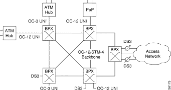
A BXM card set, using Application Specific Integrated Circuit (ASIC) technology, provides high speed ATM connectivity, flexibility, and scalability. The card set is comprised of a front card that provides the processing, management, and switching of ATM traffic and of a back card that provides the physical interface for the card set. An example of a BPX switch network provisioned with BXM-622 cards is shown in Figure 6-1.
The BXM card group includes the BXM-T3/E3, BXM-155, and BXM-622. These cards may be configured to support either trunk (network) or port (service access) interfaces. The BXM T3/E3 is available in 8 or 12 port versions with T3/E3 interfaces. The BXM-155 is available in 4 or 8 port versions with OC-3/STM-1 interfaces. The BXM-622 is available in 1 or 2 port versions with OC-12/STM-4 interfaces. The BXM card sets are compliant with ATM UNI 3.1 and Traffic Management 4.0 including ABR VSVD and provide the capacity to meet the needs of emerging bandwidth driven applications.
For additional information on ATM Connections, refer to Chapter 8, ATM Connections.
The BXM cards are designed to support all the following service classes: Constant Bit Rate (CBR), real time and no-real time Variable Bit Rate (rt-VBR and nrt-VBR), Available Bit Rate (ABR with VSVD, ABR without VSVD, and ABR using Foresight), and Unspecified Bit Rate (UBR). ABR with VSVD supports explicit rate marking and Congestion Indication (CI) control.
All software and administration firmware for the BXM card is downloadable from the BCC and is operated by the BXM on-board sub-system processor.
A BXM card set consists of a front and back card. The BXM T3/E3 is available with a universal BPX-T3/E3 backcard in 8 or 12 port versions. The BXM-OC-3 is available with 4 or 8 port multi-mode fiber (MMF), single mode fiber (SMF), or single mode fiber long reach (SMFLR) back cards. The BXM-OC-12 is available with 1 or 2 port SMF or SMFLR back cards.
Any of the 12 general purpose slots can be used for the BXM cards. The same backcards are used whether the BXM ports are configured as trunks or lines. Table 6-1 and Table 6-2 list the available front and back card options for the BXM-T3/E3, BXM-155, and BXM-622.
| Front Card Model Number | No. of Ports | Cell Buffer (ingress/egress) | Connections per card | Back Cards |
|---|---|---|---|---|
T3/E3 (45 Mbps/34Mbps) | ||||
BXM-T3-8 | 8 | 100k/130k | 16k/32k | BPX-T3/E3-BC |
BXM-E3-8 | 8 | 100k/130k | 16k/32k | BPX-T3/E3-BC |
BXM-T3-12 | 12 | 100k/230k | 16k/32k | BPX-T3/E3-BC |
BXM-E3-12 | 12 | 100k/230k | 16k/32k | BPX-T3/E3-BC |
OC-3/STM-1 (155.52 Mbps) | ||||
BXM-155-8 | 8 | 230k/230k | 16k | MMF-155-8 SMF-155-8 SMFLR-155-8 |
BXM-155-4 | 4 | 100k/230k | 16K | MMF-155-4 SMF-155-4 SMFLR-155-4 |
OC-12/STM-4 (622.08 Mbps) | ||||
BXM-622-2 | 2 | 230k/230k | 16K | SMF-622-2 SMFLR-622-2 SMFXLR-622-2 |
BXM-622 | 1 | 130k/230k | 16K/32K | SMF-622 SMFLR-622 SMFXLR-622 |
*The BXM cards can be configured for either, but not both, trunk or service access (UNI) on a card by card basis. Once a card is so configured, all ports are either trunk or service interfaces until the card is reconfigured.
**The BPX-T3/E3-BC universal backcard supports 8 or 12 ports.
| Back Card Model Number | No. of Ports | Description | Optical Range (less than or equal to) |
|---|---|---|---|
T3/E3 (45 Mbps/34 Mbps) | |||
BPX-T3/E3-BC | 8/12 | Universal T3/E3 backcard for | n/a |
|
|
|
|
OC-3/STM-1 (155.520 Mbps) | |||
MMF-155-8 | 8 | Multi-Mode Fiber | 2km |
MMF-155-4 | 4 | Multi-Mode Fiber | 2km |
SMF-155-8 | 8 | Single-Mode Fiber | 20km |
SMF-155-4 | 4 | Single-Mode Fiber | 20km |
SMFLR-155-8 | 8 | Single-Mode Fiber Long Reach | 40km |
SMFLR-155-4 | 4 | Single-Mode Fiber Long Reach | 40km |
OC-12/STM-4 (622.08 Mbps) | |||
SMF-622-2 | 2 | Single-Mode Fiber | 20km |
SMF-622 | 1 | Single-Mode Fiber | 20km |
SMFLR-622-2 | 2 | Single-Mode Fiber Long Range | 40km |
SMFLR-622 | 1 | Single-Mode Fiber Long Range | 40km |
The following lists some of the major capabilities of the BXM cards:
The BXM cards support the full range of ATM service types per ATM Forum TM 4.0.
CBR Service:
VBR Service:
ABR Service:
UBR Service:
Virtual Interfaces
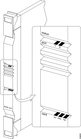
The BXM front panel has a three-section, multi-colored "card" LED to indicate the card status.
A two-port BXM-622, an 8-port BXM-155 front card, and a 12-port BXM-T3/E3 are shown in Figure 6-2, Figure 6-3, and Figure 6-4. The card status LED is color-coded as indicated in Table 6-3. A three-section multi-colored "port" LED indicates the status of the ports. Types of failures are indicated by various combinations of the card status indicators as indicated in Table 6-4.
| Status | LED color | Status Description |
|---|---|---|
port | off | Trunk/line is inactive and not carrying data. |
| green | Trunk/line is actively carrying data. |
| yellow | Trunk/line is in remote alarm. |
| red | Trunk/line is in local alarm. |
card | green (act) | Card is on-line and one or more trunks/lines on the card have been upped. If off, card may be operational but is not carrying traffic. |
| yellow (stby) | Card is off-line and in standby mode (for redundant card pairs). May not have any upped trunks/lines. If blinking, indicates card firmware or configuration data is being updated. |
| red (fail) | Card failure; card has failed self-test and/or is in a reset mode. |
| act | stby | fail | Failure Description |
|---|---|---|---|
on | off | on | Non-fatal error detected; card is still active. |
off | on | on | Non-fatal error detected; card is in standby mode. |
off | blinking | on | Fatal error detected; card is in a reboot mode. |
on | on | on | Card failed boot load and operation is halted. |

The BXM backcards connect to the BXM front cards through the StrataBus midplane.
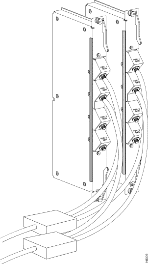
The BXM-622 is available in one or two port versions in either a single-mode fiber intermediate range (SMF) or a single-mode fiber long range (SMFLR) backcard. Connector information is listed in Table 6-5 and a 2-port SMF card is shown in Figure 6-5.
| No. | Connector | Function |
|---|---|---|
1 or 2 | PORT | Two FC connectors per port, one each for the transmit and receive signal. |
The BXM-155 is available in four or eight port versions in a choice of multi-mode fiber (MMF), single-mode fiber intermediate range (SMF), or single-mode fiber long range (SMFLR) backcards. Connector information is listed in Table 6-6 and an 8-port SMF card is shown in Figure 6-6.
| No. | Connector | Function |
|---|---|---|
4 or 8 | PORT | One SC connector per port, accommodates both the transmit and receive signals. |
The BXM-STM1-4 is available in a four-port version that provides an electrical interface where the longer line lengths provided by the BXM optical backcards are not required. Connector information is listed in Table 6-7 and the backcard is shown in Figure 6-7.
| No. | Connector | Function |
|---|---|---|
4 | PORT | Two SMB connectors per port, one each for the transmit and receive signals. |
The BXM-T3/E3 is available in eight or twelve port versions. Connector information is listed in Table 6-8 and a 12-port T3/E3 card is shown in Figure 6-8.
| No. | Connector | Function |
|---|---|---|
8 or 12 | PORT | Two SMB connectors per port, one each for the transmit and receive signals. |
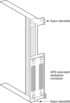
For SONET APS, card redundancy is provided by the use of two standard BXM front cards and two special backcards. The special backcards are the SMF-155-4R or -8R, SMF LR-4R or -8R, SMF -622 -1R or -2R, or SMFLR-1R or -2R. The two backcards are connected together by a BPX Redundant Backplane which mates with the BPX Midplane. The connectors are the same as for the standard backcards. An APS backcard is shown in (Figure 6-10, and the BPX Redundnant Backplane is shown in (Figure 6-11).


 BPX-T3/E3 Back Card, 12-Port Option Shown
The SMF-622 series backcards may be Y-cabled for redundancy using the Y-Cable splitter shown in Figure 6-9. The cards must be configured for Y-Cable redundancy using the addyred command.
Automatic Protection Switching (APS) provides a standards based line-redundancy for BXM OC-3 and OC-12 cards. With Release 9.2, the BXM OC-3 and BXM OC-12 cards support the SONET APS 1+1 and APS 1:1 standards for line redundancy which is provided by switching from the working line to the protection line.
The following APS protocols that are supported by the BXM are listed in Table 6-9:
| The APS 1+1 redundancy provides card and line redundancy, using the same numbered ports on adjacent BXM backcards. |
|---|---|
| The APS 1:1 redundancy provides line redundancy, using adjacent lines on the same BXM backcard. |
APS 1:1 redundancy provides line redundancy only and is supported with the standard BXM OC-3 and OC-12 front and back cards.
APS 1+1 redundancy, which provides both card and line redundancy uses the standard BXM OC-3 and OC-12 front cards, but uses a special APS Redundant Frame Assembly and APS Redundant backcards. A backcard is shown in (Figure 6-10) and the APS Redundant Frame Assembly is shown in (Figure 6-11). Two redundant backcards are connected together by the APS Redundant Frame Assembly. The APS Redundant Frame Assembly with associated APS redundant backcards is inserted as a unit in two appropriate backcard slots.
Refer to Chapter 9, SONET APS, for additional information.

This functional description provides an overview of BXM operation.
The following provides an overview of the operation of the BXM card when the ports are configured in port (access) mode for connection to customer equipment (CPE).
The ingress flow of ATM cells from CPE into a BXM port when the card is configured for port (access) operation is shown in Figure 6-12.
ATM cells from the CPE are processed at the physical interface level by the SUNI (OC-3/OC-12) or Mux/Demux (T3/E3), policed per individual VC by the RCMP and routed to applicable ingress queues. In addition, for ABR cells, additional functions are performed by the SABRE ABR connection controller, including: VSVD, Foresight, and virtual connection queueing. The cells are served out via the BPX Backplane to the BPX crosspoint switch in an order of priority based on their connection type.
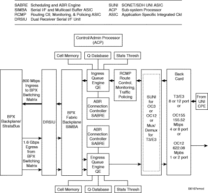
The egress flow of ATM cells out of the BXM when the card is configured for port (access) operation is shown in Figure 6-13.
ATM cells are routed to the BXM-622 via the BPX Backplane/Stratabus from the BPX crosspoint switch, applied to the DRSIU, then to an egress queue per class of service, and then served out to the SUNI (OC-3/OC-12) or Mux/Demux (T3/E3) which processes the ATM cells into frames, processing the cells from the ATM layer to the physical and on out to the CPE connected to the port(s) on the BXM backcard. For ABR cells, additional functions are performed by the SABRE ABR connection controller, including: VSVD, Foresight, and virtual connection queueing.

This provides an overview of the operation of the BXM when the card is configured in the trunk mode for connection to another node or network.
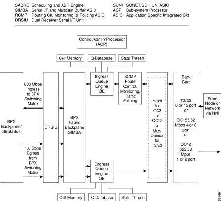
The ingress flow of ATM cells into the BXM when the card is configured for trunk operation is shown in Figure 6-14.
ATM cells from a node or network are processed at the physical interface level by the SUNI (OC-3/OC-12) or Demux/Mux (T3/E3), routed to applicable ingress slot queues, and served out to the BPX crosspoint switch via the BPX Backplane.
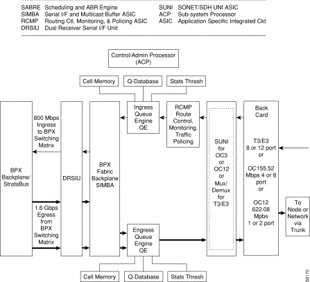
The egress flow of ATM cells out of the BXM when the card is configured for trunk operation is shown in Figure 6-15.
ATM cells are routed to the BXM from the BPX crosspoint switch, applied to the DRSIU, then to an egress queue per class of service, and then served out to the SUNI (OC-3/OC-12) or Demux/Mux (T3/E3). The SUNI or Demux/Mux, as applicable, processes the ATM cells into frames, processing the cells from the ATM layer to the physical and on out to the backcard trunk interface connecting to another node or network.
The following provides a summary of the principal functions performed by the major functional circuits of the BXM.
The DRSIU provides a total egress capacity from the BPX switch fabric of 1.6 Gbps.
The SUNI ASIC implements the BXM physical processing for OC-3 and OC-12 interfaces. The SUNI provides SONET/SDH header processing, framing, ATM layer mapping and processing functions for OC-12/STM-4 (622.08 Mbps) or OC-3/STM1 (155.52 Mbps).
For ingress traffic, the BXM physical interface receives incoming SONET/SDH frames, extracts ATM cell payloads, and processes section, line, and path overhead. For egress traffic ATM cells are processed into SONET/SDH frames.
Alarms and statistics are collected at each level: section, line, and path.
The Demux/Mux and associated circuits implement the BXM physical layer processing for T3/E3 interfaces, providing header processing, framing, ATM layer mapping, and processing functions for T3 at a 44.736 Mbps rate or E3 at a 34.368 rate.
Usage Parameter Control (UPC) is provided by the RCMP. Each arriving ATM cell header is processed and identified on a per VC basis. The policing function utilizes a leaky bucket algorithm.
In addition to UPC and traffic policing, the RCMP provides route monitoring and also terminates OAM flows to provide performance monitoring on an end-to-end per VC/VP basis.
Traffic policing and UPC functionality is in accordance with the GCRA as specified by ATM Forum's UNI 3.1 using dual leaky buckets.
In addition, two selective cell discard thresholds are supported for all queues for discard of CLP=1 cells should congestion occur.
The Scheduling and ABR Engine (SABRE) includes both VSVD and Foresight dynamic traffic transfer rate control and other functions:
The overall function of the queue engines is to manage the bandwidth of trunks or ports (UNI) via management of the ingress and egress queues.
In addition to the ABR VS queues, the ingress queues include 15 slot servers, one for each of 14 possible BPX destination slots, plus 1 for multicast operation. Each of the 15 slot servers contains 16 Qbins, supporting 16 classes of service per slot server.
In addition to the ABR VS queues, the egress queues include 32 Virtual Interfaces (VIs). Each of the 32 VIs supports 16 Qbins.
This serial interface and multicast buffer ASIC provides the following:
The ACP performs the following localized functions:
All basic configuration data on the card is copied to the battery backup memory (BRAM) on the card so that in the event of a power outage, the card will retain its main configuration.
Compliant to Bellcore GR-253-CORE
Alarms:
Performance Monitoring:
Statistics:
OAM
Compliant to Bellcore GR-253-CORE
Alarms:
Performance Monitoring:
Statistics:
Process Monitoring for ATM Header Cell Processing
Miscellaneous ATM Layer Statistics
| Back card | Source 1310 nm | Tx Power (dBm) Min Max | Rx Power (dBm) Min Max | Connection Type | Range (km) | ||
|---|---|---|---|---|---|---|---|
SMF (IR) | Laser 1310 nm | -15 | -8 | -28 | -8 | FC | 20 |
SMF (LR) | Laser 1310 nm | -3 | +2 | -28 | -8 | FC | 40 |
SMF (E) | Laser 1550 nm | -3 | +2 | -28 | -8 | FC | 40 plus |
| Back card | Source | Tx Power (dBm) Min Max | Rx Power (dBm) Min Max | Connection Type | Range (km) | ||
|---|---|---|---|---|---|---|---|
MMF | LED | -22 | -15 | -31 | -10 | SC | 2 |
SMF (IR) | Laser (Class 1) | -15 | -8 | -34 | -10 | SC | 20 |
SMF (LR) | Laser (Class 1) | -5 | 0 | -34 | -10 | SC | 40 |
SONET is defined across three elements, section, line, and path as shown in Figure 6-16 and described in Table 6-12. An advantage of this tiered approach is that management control can be exercised at each level, for example at the section level independent of the line or path level.

| Unit | Description |
|---|---|
Section | A section is the fiber optic cable between two active elements such as simple repeaters. The active element terminating these sections is called Section Terminating Equipment (STE). |
Line | A line is a physical element that contains multiple sections and repeaters and is terminated by line terminating equipment (LTE) at each end. |
Path | A path includes sections and lines and terminates at the customer premises equipment (CPE). |
Table 6-13 provides a cross-reference between OC-n optical carrier levels and the equivalent STS-n and SDH-n levels. It also includes the associated line rates.
| OC-n Optical Carrier | STS-n Synchronized Transport Signal | Line Rates (Mbps) | SDH-n Synchronized Digital Hierarchy | STM-n
Synchronous Transport Module |
|---|---|---|---|---|
OC-1 | STS-1 | 51.84 |
|
|
OC-3 | STS-3 | 155.52 | SDH-1 | STM-1 |
OC-12 | STS-12 | 622.08 | SDH-4 | STM-4 |
OC-48 | STS-48 | 2488.32 | SDH-16 | STM-12 |
This section provides a preliminary summary of configuration, provisioning, and monitoring commands associated with the BXM cards. These commands apply to initial card configuration, line and trunk configuration and provisioning, and connection configuration and provisioning.
New or modified commands include but are not limited to:
Connections are typically provisioned and configured using Cisco StrataView Plus. However, the connections can also be added using the BPX switch command line interface (CLI). This may be appropriate during initial local node setup and when a Strata View Plus workstation is not available.
There are two connection addressing modes supported. The user may enter a unique VPI/VCI address in which case the BPX switch functions as a virtual circuit switch. Or the user may enter only a VPI address in which case all circuits are switched to the same destination port and the BPX switch functions as a virtual path switch in this case. The full ATM address range for VPI and VCI is supported.
Connections are routed between CPE connected to BXM ports. Before adding connections, the BXM is configured for port mode.
A line is upped with the upln command and configured with the cnfln command. Then the associated port is configured with the cnfport command and upped with the upport command. Following this, the ATM connections are added via the addcon command.
The slot number is the BXM card slot on the BPX switch. The port number is one of the ports on the BXM, the VPI is the virtual path identifier, and the VCI is the virtual circuit identifier.
The VPI and VCI fields have significance only to the local BPX switch, and are translated by tables in the BPX switch to route the connection. Connections are automatically routed by the AutoRoute feature once the connection endpoints are specified.
Connections can be either Virtual Path Connections (VPC) or Virtual Circuit Connections (VCC). Virtual Path Connections are identified by an * in the VCI field. Virtual Circuit Connections specify both the VPI and VCI fields.
The following parameters are entered for the BXM addcon command. Depending upon the connection type, the user is prompted with appropriate parameters as shown below.
Syntax:
addcon local_addr node remote_addr traffic_type ...extended parameters
| Field | Value | Description |
|---|---|---|
local/remote_addr | slot.port.vpi.vci | card slot, port, and desired VCC or VPI connection identifier |
node |
| slave end of connection |
traffic_type |
| type of traffic, chosen from CBR, VBR, ABR, and UBR |
extended parameters |
| parameters associated with each connection type |
The following pages have a number of command examples, including configuring BXM lines and trunks and adding connections terminating on BXM cards.
An example of the uptrk command for trunk 1 on a BXM in slot 4 of a BPX switch follows:
pubsbpx1       TN    silves          BPX 8620  9.2.2G    Aug. 2 1999  13:42 PDT

TRK       Type     Current Line Alarm Status               Other End
 1.1      T3       Clear - OK                              -
 2.1      OC-3      Clear - OK                              VSI(VSI)
 4.1      OC-3      Clear - OK                              -


Last Command: uptrk 4.1

256 PVCs allocated. Use 'cnfrsrc' to configure PVCs
Next Command:
An example of the cnftrk command for trunk 4.1 of a BXM card follows:
pubsbpx1       TN    silves          BPX 8620  9.2.2G    Aug. 2 1999  13:40 PDT

TRK  4.1 Config    OC-3     [353207cps]     BXM slot:     2
Transmit Rate:         353208              Line framing:          STS-3C
Protocol By The Card:  No                       coding:           --
VC Shaping:            No                       CRC:              --
Hdr Type NNI:          Yes                      recv impedance:   --
Statistical Reserve:   1000    cps              cable type:       --
Idle code:             7F hex                         length:     --
Connection Channels:   256                 Pass sync:             No
Traffic:V,TS,NTS,FR,FST,CBR,NRT-VBR,ABR, T-VBR  clock:            No
SVC Vpi Min:           0                   HCS Masking:           Yes
SVC Channels:          0                   Payload Scramble:      Yes
SVC Bandwidth:         0      cps          Frame Scramble:        Yes
Restrict CC traffic:   No                  Virtual Trunk Type:    --
Link type:             Terrestrial         Virtual Trunk VPI:     --
Routing Cost:          10                  Deroute delay time:    0 seconds

This Command: cnftrk 4.1


Transmit Rate [ 1-353208 ]:
An example of the addtrk command follows:
pubsbpx1       TN    silves         BPX 8620  9.2.2G    Aug. 2 1999  13:45 PDT

TRK       Type     Current Line Alarm Status               Other End
 1.1      T3       Clear - OK                              -
 2.1      OC-3      Clear - OK                              VSI(VSI)
 2.4      OC-3      Clear - OK                              -


Last Command: dsptrks


Next Command:
An example of the upln command for UNI port access on a BXM card follows:
pubsbpx1       TN    StrataCom       BPX 8620  9.2.2G    Aug. 2 1999  13:54 PDT

Line      Type     Current Line Alarm Status
 2.2      OC-3      Clear - OK
 2.3      OC-3      Clear - OK


Last Command: upln 2.2

256 PVCs allocated. Use 'cnfrsrc' to configure PVCs
Next Command:
An example of the cnfln command follows:
pubsbpx1       TN    StrataCom       BPX 8620  9.2.2G    Aug. 2 1999  13:55 PDT

LN   2.2 Config    OC-3     [353208cps]     BXM slot:     2
Loop clock:            No                  Idle code:             7F hex

Line framing:          --
     coding:           --
     CRC:              --
     recv impedance:   --
     E1 signalling:    --
     encoding:         --                       cable type:       --
     T1 signalling:    --                       length:           --
                                           HCS Masking:           Yes
                                           Payload Scramble:      Yes
     56KBS Bit Pos:    --                  Frame Scramble:        Yes
     pct fast modem:   --                  Cell Framing:          STS-3C
                                           VC Shaping:            No

This Command: cnfln 2.2


Loop clock (N):
An example of the cnfport command for port 3 of a BXM card in slot 3 follows:
pubsbpx1       TN    silves          BPX 8620  9.2.2G    Aug. 2 1999  13:56 PDT

Port:       2.2     [INACTIVE]
Interface:          LM-BXM                     CAC Override:     Enabled
Type:               UNI                        %Util Use:        Disabled
Shift:              SHIFT ON HCF (Normal Operation)
SIG Queue Depth:    640                        Port Load:        0 %

Protocol:           NONE                       Protocol by Card: No


This Command: cnfport 2.2


NNI Cell Header Format? [N]:
An example of the cnfportq command follows:
pubsbpx1       TN    silves          BPX 8620  9.2.2G    Aug. 2 1999  13:57 PDT

Port:       2.2     [INACTIVE]
Interface:          LM-BXM
Type:               UNI
Speed:              353208 (cps)

SVC Queue Pool Size:          0
CBR Queue Depth:              600     rt-VBR Queue Depth:                5000
CBR Queue CLP High Threshold: 80%     rt-VBR Queue CLP High Threshold:   80%
CBR Queue CLP Low Threshold:  60%     rt-VBR Queue CLP Low/EPD Threshold: 60%
CBR Queue EFCI Threshold:     60%     rt-VBR Queue EFCI Threshold:       60%
nrt-VBR Queue Depth:          5000    UBR/ABR Queue Depth:               20000
nrt-VBR Queue CLP High Threshold: 80% UBR/ABR Queue CLP High Threshold:  80%
nrt-VBR Queue CLP Low Threshold:  60% UBR/ABR Queue CLP Low/EPD Threshold:60%
nrt-VBR Queue EFCI Threshold: 60%     UBR/ABR Queue EFCI Threshold:      20%


This Command: cnfportq 2.2


SVC Queue Pool Size [0]:
An example of the upport command follows:
pubsbpx1       TN    silves          BPX 8620  9.2.2G    Aug. 2 1999  13:58 PDT

Port:       2.2     [ACTIVE  ]
Interface:          LM-BXM                     CAC Override:     Enabled
Type:               UNI                        %Util Use:        Disabled
Shift:              SHIFT ON HCF (Normal Operation)
SIG Queue Depth:    640                        Port Load:        0 %

Protocol:           NONE                       Protocol by Card: No


Last Command: upport 2.2


Next Command:
An example of the cnfatmcls command for class 2 follows:
pubsbpx1       TN    StrataCom       BPX 8620  9.2.2G    Aug. 2 1999  13:59 PDT

                        ATM Connection Classes
Class:  2                                                         Type: nrt-VBR
   PCR(0+1)     % Util       CDVT(0+1)       AAL5 FBTC        SCR
 1000/1000     100/100      10000/10000          n        1000/1000

     MBS         Policing
 1000/1000           3

       Description: "Default nrt-VBR 1000 "


This Command: cnfatmcls 2


Enter class type (rt-VBR, nrt-VBR, CBR, UBR, ABRSTD, ABRFST, ATFR, ATFST, ATFT,
ATFTFST, ATFX, ATFXFST):
An example of the cnfcls command for class 3 follows:
pubsbpx1       TN    StrataCom       BPX 8620  9.2.2G    Aug. 2 1999  14:02 PDT

                        ATM Connection Classes
Class:  3                                                         Type: rt-VBR
   PCR(0+1)     % Util       CDVT(0+1)       AAL5 FBTC        SCR
 4000/4000     100/100      10000/10000          n        4000/4000

     MBS         Policing
 1000/1000           3

       Description: "Default rt-VBR 4000 "


This Command: cnfatmcls 3


Enter class type (rt-VBR, nrt-VBR, CBR, UBR, ABRSTD, ABRFST, ATFR, ATFST, ATFT,
ATFTFST, ATFX, ATFXFST):
An example of the addcon command for a VBR connection 3.1.105.55 that originates at port 2 of a BXM card in slot 2 follows:
pubsbpx1       TN    silves          BPX 8620  9.2.2G    Aug. 2 1999  14:05 PDT

 Local           Remote      Remote                             Route
 Channel         NodeName    Channel         State  Type        Avoid COS O
 2.2.16.16       pubsbpx1    2.3.66.66       Ok     rt-vbr
 2.3.66.66       pubsbpx1    2.2.16.16       Ok     rt-vbr


Last Command: addcon 2.2.16.16 pubsbpx1 2.3.66.66 rt-VBR * * * * * * *


Next Command:
An example of the cnfcon command for a rt-VBR connection 2.2.16.16 follows.
pubsbpx1       TN    silves          BPX 8620  9.2.2G    Aug. 2 1999  14:06 PDT

Conn:  2.2.16.16        pubsbpx1    2.3.66.66         rt-vbr    Status:OK
   PCR(0+1)     % Util       CDVT(0+1)       AAL5 FBTC        SCR
   50/50       100/100     250000/250000         n          50/50

     MBS         Policing
 1000/1000           3


This Command: cnfcon 2.2.16.16


PCR(0+1) [50/50]:
An example of the addcon command for an ABR connection follows. In this case, the choice to accept the default parameters was not accepted, and individual parameters were configured for a connection using ABR standard VSVD flow control.
pubsbpx1       TN    StrataCom       BPX 8620  9.2.2G    Aug. 2 1999  14:12 PDT

 From            Remote      Remote                             Route
 2.2.17.17       NodeName    Channel         State  Type        Avoid COS O
 2.3.66.66       pubsbpx1    2.2.16.16       Ok     rt-vbr


This Command: addcon 2.2.17.17 pubsbpx1 2.3.67.67 abrstd 100/100 95/95 * * e e e
 d 70/70 * 3 * * * 65/65 * * * * * * * *

Add these connections (y/n)? y
An example of the cnfcon command for an ABR connection follows:
pubsbpx1       TN    silves         BPX 8620  9.2.2G    Aug. 2 1999  14:14 PDT

Conn:  2.2.17.17        pubsbpx1    2.3.67.67         abrstd    Status:OK
   PCR(0+1)     % Util      MCR            CDVT(0+1)       AAL5 FBTC VSVD  FCES
  100/100       95/95     50/50          250000/250000         y      y     y

     SCR            MBS      Policing   VC Qdepth    CLP Hi CLP Lo/EDP    EFCI
   70/70        1000/1000        3    16000/16000    80/80    35/35      65/65

     ICR           ADTF  Trm     RIF      RDF    Nrm     FRTT            TBE
   50/50           1000  100        128    16     32           0        1048320


This Command: cnfcon 2.2.17.17


PCR(0+1) [100/100]:
An example of the cnfabrparm command follows:
pubsbpx1       TN    YourID:1       BPX 15    9.2       Jun. 8 1998  00:21 GMT

ABR Configuration for BXM in slot 3

Egress CI Control  : N
ER Stamping        : N
Weighted Queueing  : N


Last Command: cnfabrparm 3


Next Command:
An example of the dsplns command follows:
pubsbpx1       TN    YourID       BPX 15    9.2       Jun. 8 1998  00:22 GMT

Line    Type   Current Line Alarm Status
 3.1    OC-3    Clear - OK
 3.2    OC-3    Clear - OK
 3.3    OC-3    Clear - OK
 3.4    OC-3    Clear - OK
 5.1    T3     Clear - OK
 5.2    T3     Clear - OK


Last Command: dsplns


Next Command:
During the configuration of BPX switch interfaces, you must make sure that the BPX switch IP address, SNMP parameters, and Network IP address are set consistent with your local area network (Ethernet LAN). Use the following BPX switch commands to set these parameters:
The use of these commands is covered in the Cisco WAN Switching Command Reference or the Cisco WAN Switching Superuser Command Reference. SuperUser commands must be used only by authorized personnel, and must be used carefully.
MGX 8220 installation and configuration are covered in the Cisco MGX 8220 Reference. During the configuration of BPX switch interfaces, you must make sure that the MGX 8220 IP address is set up consistent with your local area network (Ethernet LAN). Use the following MGX 8220 command to set the proper IP addresses:
cnfifip -ip <ip address> -if <interface type> -msk <subnet mask address> -bc <broadcast address>
The use of this command is covered in the Cisco MGX 8220 Command Reference.
Resources on BPX switch UNI ports and NNI trunks can be divided between SVCs and PVCs, or LVCs and PVCs. This is known as resource partitioning and is done through the Command Line Interface for the BPX switch and the MGX 8220.
These resources for BXM, ASI, and BNI cards can be partitioned appropriately between SVCs or PVCs.
The BXM also supports Multiprotocol Label Switching (MPLS). Partitions for the BXM can be allocated either between:
For information on MPLS Switching, refer to Chapter 16, MPLS on BPX Switch.
The BXM card supports dynamic resource partitioning to support the conversion of PVCs to soft permanent virtual circuits (SPVCs). This feature is described in the Cisco WAN Service Node Extended Services Processor Installation and Operations for Release 2.2 document.
This section provides procedures for:
A BXM card used as a UNI port can be configured to support ATM SVCs. The BXM will have to be added and upped like a standard PVC port. The BXM port will have to upped as a line (upln) to function as a UNI port.
For additional information on using the BPX switch command line interface and applicable commands, refer to the Cisco WAN Switching Command Reference manual. These procedures will concentrate on those commands that are specific to SVC resource partitioning.
Before partitioning SVC resources, you must determine which BXM UNI ports will support ATM SVCs. The BXM must have its resources partitioned to support SVCs. The following resources must be partitioned:
To partition the BXM port, follow these steps:
Step 2 Using the upln and upport commands, up the line and port which is going to be connected to ATM CPE.
Step 3 Make sure the port is configured as UNI.
Step 4 Enter the cnfport <port num> command, shown in the following example:
Example: BXM cnfport Command
ins-bpx6       TN    SuperUser       BPX 15    9.2   Sep. 24 1998 07:37 GMT

Port:       13.1    [ACTIVE  ]
Interface:          LM-BXM
Type:               UNI                        %Util Use:        Disabled
Speed:              353208 (cps)
Shift:              SHIFT ON HCF (Normal Operation)
SIG Queue Depth:    640

Protocol:           NONE
  SVC Channels:                       1000
  SVC VPI Min:                        0
  SVC VPI Max:                        10
  SVC Bandwidth:                      300000 (cps)


This Command: cnfport 13.1


NNI Cell Header Format? [N]:
Step 5 Configure the SVC Channels, SVC VPI Min, SVC VPI Max, and SVC Bandwidth as desired.
Step 6 Next you need to configure the SVC Port Queue depth with the cnfportq <portnum> command shown in the following example.
ins-bpx6       TN    SuperUser       BPX 15    9.2    Sep. 24 1998 07:39 GMT

Port:       13.1    [ACTIVE  ]
Interface:          LM-BXM
Type:               UNI
Speed:              353208 (cps)

SVC Queue Pool Size:          5000
CBR Queue Depth:              600
CBR Queue CLP High Threshold: 80%
CBR Queue CLP Low Threshold:  60%
CBR Queue EFCI Threshold:     80%
VBR Queue Depth:              5000    UBR/ABR Queue Depth:               20000
VBR Queue CLP High Threshold: 80%     UBR/ABR Queue CLP High Threshold:  80%
VBR Queue CLP Low Threshold:  60%     UBR/ABR Queue CLP Low Threshold:   60%
VBR Queue EFCI Threshold:     80%     UBR/ABR Queue EFCI Threshold:      30%


This Command: cnfportq 13.1


SVC Queue Pool Size [5000]:
Step 7 Configure the SVC Queue Pool Size parameter to a value greater than 0 (zero); the default is 0 and needs to be changed for SVCs to operate.
Step 8 Partition the SVC resources for every BXM which is to support ATM SVCs in the BPX switch.
The BXM card may have resources partitioned to support SVCs.
When the BXM is used as a trunk in a BPX switch network, it needs to have its resources partitioned to support SVCs. The BXM card will have to upped as a trunk (uptrk).
For additional information on using the BPX switch command line interface and applicable commands refer to the Cisco WAN Switching Command Reference manual. These procedures concentrate on those commands that are specific to SVC resource partitioning.
The following BXM trunk resources must be partitioned for SVCs:
To partition the BXM trunk resources for SVCs, follow these steps:
Step 2 Make sure the BXM has been upped as a trunk with uptrk <trunk_num> command.
Step 3 Enter the cnftrk <trk num> command, shown in the following example:
Example: BXM cnftrk Command
pubsbpx1       TN    silves          BPX 8620  9.2.2G    Aug. 2 1999  14:23 PDT

TRK  2.4 Config    OC-3     [353207cps]     BXM slot:     2
Transmit Rate:         353208              Line framing:          STS-3C
Protocol By The Card:  No                       coding:           --
VC Shaping:            No                       CRC:              --
Hdr Type NNI:          Yes                      recv impedance:   --
Statistical Reserve:   1000    cps              cable type:       --
Idle code:             7F hex                         length:     --
Connection Channels:   256                 Pass sync:             No
Traffic:V,TS,NTS,FR,FST,CBR,NRT-VBR,ABR, T-VBR  clock:            No
SVC Vpi Min:           0                   HCS Masking:           Yes
SVC Channels:          0                   Payload Scramble:      Yes
SVC Bandwidth:         0      cps          Frame Scramble:        Yes
Restrict CC traffic:   No                  Virtual Trunk Type:    --
Link type:             Terrestrial         Virtual Trunk VPI:     --
Routing Cost:          10                  Deroute delay time:    0 seconds

This Command: cnftrk 2.4


Transmit Rate [ 1-353208 ]:
Step 4 Configure the SVC VPI Min, SVC Channels and SVC Bandwidth as desired.
Step 5 Next configure the SVC Queue depth with cnftrkparms <trunk_num> command shown in the following example:
Example: BXM cnftrkparm Command
pubsbpx1       TN    silves          BPX 8620  9.2.2G    Aug. 2 1999  14:24 PDT

TRK 2.4 Parameters
 1 Q Depth - rt-VBR    [  885] (Dec)    15 Q Depth   - CBR     [  600] (Dec)
 2 Q Depth - Non-TS    [ 1324] (Dec)    16 Q Depth   - nrt-VBR [ 5000] (Dec)
 3 Q Depth - TS        [ 1000] (Dec)    17 Q Depth   - ABR     [20000] (Dec)
 4 Q Depth - BData A   [10000] (Dec)    18 Low  CLP  - CBR     [  60] (%)
 5 Q Depth - BData B   [10000] (Dec)    19 High CLP  - CBR     [  80] (%)
 6 Q Depth - High Pri  [ 1000] (Dec)    20 Low  CLP  - nrt-VBR [  60] (%)
 7 Max Age - rt-VBR    [   20] (Dec)    21 High CLP  - nrt-VBR [  80] (%)
 8 Red Alm - I/O (Dec) [  2500 /  10000]22 Low CLP/EPD-ABR     [  60] (%)
 9 Yel Alm - I/O (Dec) [  2500 /  10000]23 High CLP  - ABR     [  80] (%)
10 Low  CLP - BData A  [ 100] (%)       24 EFCN      - ABR     [  20] (%)
11 High CLP - BData A  [ 100] (%)       25 SVC Queue Pool Size [    0] (Dec)
12 Low  CLP - BData B  [  25] (%)
13 High CLP - BData B  [  75] (%)
14 EFCN     - BData B  [  30] (Dec)

This Command: cnftrkparm 2.4


Which parameter do you wish to change:
Step 6 Configure the SVC Queue Pool Size as desired.
Step 7 Partition the SVC resources for all the other BXMs in the BPX switch.
![]()
![]()
![]()
![]()
![]()
![]()
![]()
![]()
Posted: Sun Jan 14 18:37:48 PST 2001
All contents are Copyright © 1992--2001 Cisco Systems, Inc. All rights reserved.
Important Notices and Privacy Statement.