|
|

This chapter contains a description of the ATM Service Interface (ASI) and associated backcards.For a description of the BXM cards which provide both service interfaces (line) and network interfaces (trunk), refer to Chapter 6, BXM T3/E3, 155, and 622.
This chapter contains the following:
The BPX switch service interface group of cards provides an ATM interface between the BPX switch and CPE (see Figure 5-1). The ASI series of cards (DS3, E3, and OC-3) are described in this chapter.
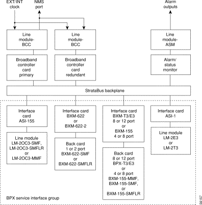
The ATM Service Interface Card for T3 and E3 interfaces (ASI-1) is a front card for use in the BPX switch to interface an ATM user device, such as, Customer Premise Equipment (CPE). The ASI provides an industry-standard ATM User-to-Network Interface (UNI) or ATM Network-to-Network Interface (NNI) to the BPX switching fabric.
A summary of features for the ASI card include:
Each ASI-1 card provides two ATM UNI/NNI ports, each operating at DS3 rates or E3 rates (see Figure 5-2). Any of the 12 general purpose slots can be used to hold these cards. The ASI-1 operates with a corresponding T3 or E3 Line Module back card LM-2T3 or LM-2E3, respectively. Only the first two connectors on the back card are active; the lower port is not used.
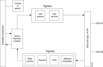
Each port provides an aggregate ATM connection bandwidth of 96,000 cells/second (T3)
or 80,000 cells/sec (E3), or 353,208 cells/sec (OC-3).
Connections are added using the addcon command.
Some of the functions performed by the PLPP in the ASI-1 include:
PLPP—Receiver Side
Connections are routed using the VPI and VCI address fields in the UNI header. The allowable range for VPI is from 0 to 255 (UNI) and 0 to 1023 (NNI), while VCI can range from 1 to 65535. A total of 1000 combinations of these can be used per ASI card at any one time.
A total of 1000 logical connections (ungrouped) may be configured for the node at any one time. On the BPX switch, 5000 grouped connections can be configured. The ASI-1 supports 1000 connections per card.
Two connection addressing modes are supported. The user may enter a unique VPI/VCI address in which case the BPX switch functions as a virtual circuit switch. Or the user may enter only a VPI address in which case all circuits are switched to the same destination port and the BPX switch functions as a virtual path switch in this case.
There are sixteen egress queues per line (port), including CBR, VBR, and ABR. When a connection is added, the user selects either constant bit rate (CBR), variable bit rate (VBR), or available bit rate (ABR, which uses ForeSight). The CBR queue has higher priority. Queue depth is specified when configuring a line. Maximum depth that can be specified for any one queue is 11,000 cells. Total queue depth cannot exceed 22,000 cells.
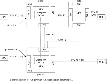
Connections are routed between CPE connected to ASI ports (see Figure 5-3). Before adding connections, an ASI line is upped with the upln command and configured with the cnfln command. Then the associated port is configured with the cnfport command and upped with the upport command. Following this, the ATM connections are added via the addcon command with the syntax: slot.port.vpi.vci. The example shows a connection between alpha 4.1.1.1 and gamma 6.1.1.1.
The slot number is the ASI card slot on the BPX switch. The port number is one of two ports on the ASI, the VPI is the virtual path identifier, and the VCI is the virtual circuit identifier. (The top two ports on the LM-2T3 card are used, the bottom one is not.)
The VPI and VCI fields have significance only to the local BPX switch, and are translated by tables in the BPX switch to route the connection. Connections are automatically routed by the AutoRoute feature once the connection endpoints are specified.
Connections can be either Virtual Path Connections (VPC) or Virtual Circuit Connections (VCC). Virtual Path Connections are identified by an * in the VCI field. Virtual Circuit Connections specify both the VPI and VCI fields. Refer to the Cisco WAN Switching Command Reference for further information.
Port, line, and channel statistics are collected by the ASI-1. Refer to the Cisco StrataView Plus Operations Guide for a listing and description of these statistics.
The ASI front panel (see Figure 5-4) has a three-section, multicolored "card" LED to indicate the card status. The card status LED is color-coded as indicated in Table 5-1. A two-section multicolored "port" LED indicates the status of the two ports on the ASI. The port status LED display is color-coded as indicated in Table 5-1.
| Status | LED color | Status Description |
|---|---|---|
port | off | Line is inactive and not carrying data. |
| green | Line is actively carrying data. |
| yellow | Line is in remote alarm. |
| red | Line is in local alarm. |
card | green (act) | Card is on-line and one or more ports on the card have been upped. If off, card may be operational but is not carrying traffic. |
| yellow (stby) | Card is off-line and in standby mode (for redundant card pairs). May not have any upped ports. If blinking, indicates card firmware or configuration data is being updated. |
| red (fail) | Reserved for card failure. |

The Line Modules for the ASI-T3 and ASI-E3 front cards are back cards used to provide a physical interface to the transmission facility. They are the same backcards used by the BNI-T3 and BNI-E3, except that only two ports are used by the ASI. The LM-3T3 is used with the BNI-T3 and the LM-3E3 with the BNI-3E3. The Line Module connects to the BNI through the StrataBus midplane. Two adjacent cards of the same type can be made redundant by using a Y-cable at the port connectors. All three ports on a card must be configured the same.
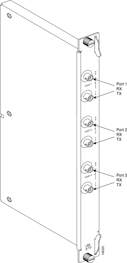
Refer to Figure 5-5, Figure 5-6, and Table 5-2 which describe the faceplate connectors of the LM-3T3 and LM-3E3. There are no controls or indicators.
The LM-3T3 and LM-3E3 provide the following features:
A final node loopback is found at the end of the LM-3T3 or LM-3E3 card. This is a metallic loopback path that uses a relay contact closure. It is a near-end loopback path only; the signal is looped at the final output stage back to circuits in the node receive side. It is only operated when the corresponding front card is in standby.
| No | Connector | Function |
|---|---|---|
1 | PORT 1 RX - TX | BNC connectors for the transmit and receive T3/E3 signal to/from ATM trunk 1. |
2 | PORT 2 RX - TX | BNC connectors for the transmit and receive T3/E3 signal to/from ATM trunk 2. |
3 | PORT 3 RX - TX | BNC connectors for the transmit and receive T3/E3 signal to/from ATM trunk 3. |

The ATM Service Interface Card for OC-3/STM-1, the ASI-155, is a BPX switch front card used to interface with an ATM user device e.g., CPE. The ASI provides an industry-standard ATM User-to-Network Interface (UNI) or ATM Network-to-Network Interface (NNI) over OC-3 lines to the BPX switching fabric.
There are three ASI-155 back cards, the LM-2OC-3-SMF for single-mode fiber intermediate range, the LM-2OC-3-SMFLR for single-mode fiber long range, and the LM-2OC-3-MMF for multi-mode fiber. Any of the 12 general purpose slots can be used to hold these cards. These backcards may also be used with the BNI-155
A summary of features for the ASI-155 card include:
Connections are routed using the VPI and VCI address fields in the UNI header. The allowable range for VPI is from 0 to 255 (UNI) and 0 to 1023 (NNI), while VCI can range from 1 to 65535. A total of 1000 combinations of these can be used per ASI card at any one time. Future releases will support the full ATM address range.
There are two connection addressing modes supported. The user may enter a unique VPI/VCI address in which case the BPX switch functions as a virtual circuit switch. Or the user may enter only a VPI address in which case all circuits are switched to the same destination port and the BPX switch functions as a virtual path switch in this case.
There are 12 egress queues per line (port), two of which are used. These are for CBR and VBR. When a connection is added, the user selects either a constant bit rate (CBR) or variable bit rate (VBR) connection class.
Connections are routed between CPE connected to ASI ports. Before adding connections, an ASI line is upped with the upln command and configured with the cnfln command. Then the associated port is configured with the cnfport command and upped with the upport command. Following this, the ATM connections are added via the addcon command with the syntax: slot.port.vpi.vci.
The slot number is the ASI card slot on the BPX switch. The port number is one of two ports on the ASI, the VPI is the virtual path identifier, and the VCI is the virtual circuit identifier.
The VPI and VCI fields have significance only to the local BPX switch and are translated by tables in the BPX switch to route the connection. Connections are automatically routed by the AutoRoute feature once the connection endpoints are specified.
Connections can be either Virtual Path Connections (VPC) or Virtual Circuit Connections (VCC). Virtual Path Connections are identified by an * in the VCI field. Virtual Circuit Connections specify both the VPI and VCI fields.
ATM to Frame Relay Network and Service Interworking connections to the ASI are also supported. In the case of Network Interworking, the user CPE must be aware of the interworking function and provide the appropriate protocol mapping.
Refer to the Cisco WAN Switching Command Reference for further information.
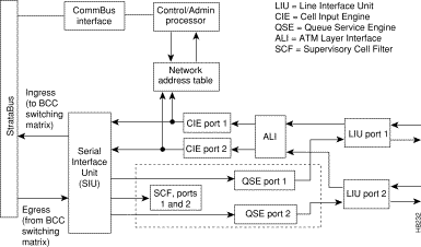
For ingress traffic, the ATM Layer Interface (ALI) provides traffic management and admission controls (UPC) for the ASI-155 (see Figure 5-7). The ASI-155 supports CBR and VBR connections and employs a single leaky bucket GCRA mechanism for policing cell streams seeking entrance to the network. Each PVC (VPC.VCC) is policed separately, providing firewalling between connections, and assuring that each connection uses only a fair share of network bandwidth. The ALI also performs ingress OAM functions.
The single leaky bucket policing function is implemented using a GCRA (Generic Rate Algorithm) defined by two parameters:
In the ingress direction, the ASI-155 has 2 Cell Input Engines (CIEs) that convert the incoming cell headers to the appropriate connection ID based on input from a Network Address Table.
For egress traffic, the Supervisory Cell Filter (SCF) provides routing and direction of non-data cells, such as test cells and OAM cells.
The Serial Interface Unit (SIU) provides the ASI with an 800 Mbps cell interface to the StrataBus. It provides serial-to-parallel conversion of data, along with loopback and test signal generation capabilities.
The Line Interface Unit (LIU) performs the following ingress functions:
The Line Interface Unit (LIU) performs the following egress functions:
Port, line, and channel statistics are collected by the ASI-155. The StrataView Plus workstation is used to collect and monitor these statistics. For additional information regarding ASI-155 statistics refer to the Cisco StrataView Plus Operations Guide.
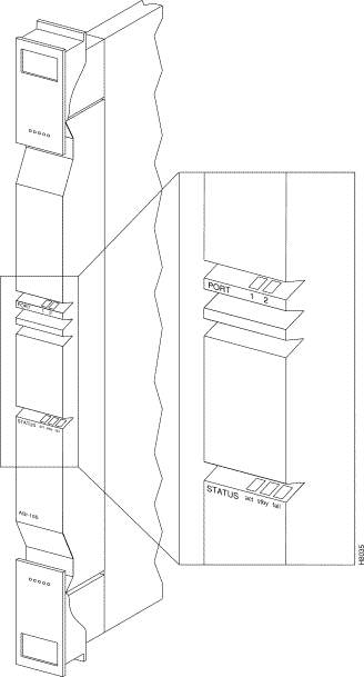
The ASI-155 front panel (see Figure 5-8) has a three-section, multicolored "card" LED to indicate the card status. The card status LED is color-coded as indicated in Table 5-3. A two-section multicolored "port" LED indicates the status of the two ports on the ASI-155. The port status LED display is color-coded as indicated in Table 5-3.
| Status | LED color | Status Description |
|---|---|---|
port | off | Line is inactive and not carrying data. |
| green | Line is actively carrying data. |
| yellow | Line is in remote alarm. |
| red | Line is in local alarm. |
card | green (act) | Card is on-line and one or more ports on the card have been upped. If off, card may be operational but is not carrying traffic. |
| yellow (stby) | Card is off-line and in standby mode (for redundant card pairs). May not have any upped ports. If blinking, indicates card firmware or configuration data is being updated. |
| red (fail) | Reserved for card failure. |
The LM- 2OC-3 -SMF (Model SMF-2-BC) line module for the ASI-155 Front Card is a backcard that provides a SMF intermediate range service interface. The line module connects to the ASI-155 through the StrataBus midplane. Two adjacent cards of the same type can be made redundant by using a Y-cable at the port connectors. This is the same LM-2OC-3-SMF backcard (Figure 4-8) that is used for the BNI-155.
The LM- 2OC-3 -SMFLR (Model SMFLR-2-BC) line module for the ASI-155 Front Card is a backcard that provides a SMF long range service interface. The line module connects to the ASI-155 through the StrataBus midplane. This is the same LM-2OC-3-SMFLR backcard that is used for the BNI-155.
The LM-2OC-3 -MMF (Model MMF-2-BC) line module for the ASI-155 Front Card is a backcard that provides a MMF service interface (Figure 4-9). The line module connects to the ASI-155 through the StrataBus midplane. This is the same LM-2OC-3-SMF backcard that is used for the BNI-155.
The LM-OC-3-SMF (Model SMF-2-BC) backcards may be Y-cabled for redundancy using the Y-Cable splitter (Model SMFY) as shown in Figure 4-10. The cards must be configured for Y-Cable redundancy using the addyred command
![]()
![]()
![]()
![]()
![]()
![]()
![]()
![]()
Posted: Sun Jan 14 18:42:14 PST 2001
All contents are Copyright © 1992--2001 Cisco Systems, Inc. All rights reserved.
Important Notices and Privacy Statement.