|
|

This chapter provides a brief overview of switched virtual circuits and soft permanent virtual circuits with respect to the BPX switch and co-located Extended Services Processor. For additional information, refer to the Cisco WAN Service Node Extended Services Processor Installation and Operation Release 2.2 document.
This chapter contains the following:
With a co-located Extended Services Processor (ESP), the BPX switch adds the capability to support ATM and Frame Relay switched virtual circuits (SVCs) in addition to support for permanent virtual circuits (PVCs) as shown in Figure 10-1.
The Private Network to Network Interface (PNNI) protocol is used to route SVCs across the network. PNNI provides a dynamic routing protocol which is responsive to changes in network availability and will scale to large networks.
BPX switch resources, such as port VPI range and trunk bandwidth are partitioned between SVCs and PVCs. This provides a firewall between the two types of connections so that any SVCs that come on-line and off-line do not affect the availability of existing PVC services.
The following connections are supported with Release 9.1:
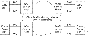
Both permanent virtual circuits and switched virtual circuits are defined by ATM and Frame Relay standards groups.
After being added to a network, permanent virtual circuits (PVCs) remain relatively static. The PVC only allocates a physical circuit and consumes bandwidth when there is data to send. However, the permanent virtual circuit remains in place, always available for use, and is similar to a dedicated private line in this respect.
Soft permanent virtual circuits (SPVCs) are PVCs which are routed using the Private Network-Network Interface (PNNI) routing protocol. The "permanent" qualifier indicates that the virtual connection is established administratively, through an operator's command, rather than on demand by signaling. A soft PVC is one where the establishment within the network is done by the ESP signaling (in this case, PNNI signaling), just as it is done for Frame Relay and ATM switched virtual circuits.
In the PNNI network, SPVC connections are established using the best available route. During a network failure, SPVC connections could be rerouted and the newly selected path many not be the optimal route. The ESP's SPVC feature provides for auto-grooming of SPVCs. Auto-grooming is a background management process that evaluates SPVC connections; if a better path for the connection is found, the SPVC will be released and rerouted to the optimized path.
Refer to the Cisco WAN Service Node Extended Services Processor Installation and Operation for Release 2.2 document for detailed information about SPVCs.
A switched virtual circuit (SVC) only exists when there is data to send and a calling process has been initiated. With a switched virtual circuit, there must be some signaling mechanism to build a connection each time the user (ATM or Frame Relay device in this case) needs it. In addition, when the call is disconnected, there must be a mechanism for the orderly disconnection of the call, and the network's resources must be relinquished. During a disconnect, the Cisco StrataCom network sweeps through its connection tables and removes the connection.
ATM SVCs are ATM connections setup and maintained by a standardized signaling mechanism between ATM CPE (ATM user end systems) across a Cisco StrataCom network. ATM SVCs are created on user demand and removed when the call is over, thus freeing up network resources.
Frame Relay SVCs are Frame Relay connections setup and maintained by a standardized signaling mechanism between Frame Relay CPE (Frame Relay user end systems) across a Cisco StrataCom network. Frame Relays SVCs are created on user demand and removed when the call is over, thus freeing up network resources.
The BPX switch supports the UNI and NNI interfaces for SVC operations as described in the following:
Interim Interswitch Protocol (IISP) is an interim static routing protocol defined by the ATM Forum to provide base level capability until the Private Network to Network Interface (PNNI) was specified. The IISP provides users with some level of multi-vendor switch interoperability based on the existing ATM Forum UNI 3.1 specifications. IISP assumes no exchange of routing information between switching systems. It uses a a fixed routing algorithm with static routes. Routing is done on a hop-by-hop basis by making a best match of the destination address in the call setup with address entries in the next hop routing table at a given switching system. Entries in the next hop routing table are configured by the user.
The Private Network to Network Interface standards essentially define two protocols:
To support ATM and Frame Relay SVCs, the BPX switches essentially overlay a signaling network over a traditional (that is PVC-based) network. This signaling network, indicated by the dashed lines in Figure 10-2, connects all of the BPX switches with ESP and extends to the CPE. The signaling plane establishes and maintains SVCs between the CPE, that is, end users, across a Cisco StrataCom wide-area ATM network.
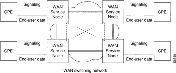
The signaling plane is created out of two basic types of signaling channels:
The signaling VCCs are normally configured during the provisioning of UNI ports and NNI trunks.
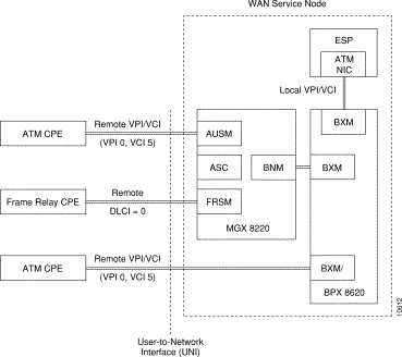
There is an internal signaling VCC established between every UNI port on the BPX switch which will support ATM or Frame Relay SVCs and the ESP in the BPX switch.There are two types of UNI signaling channels supported by the BPX switch as shown in Figure 10-3.
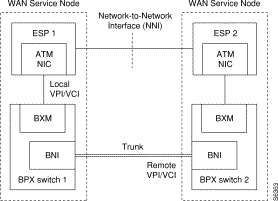
There is also a signaling channel established between each adjacent pair of BPX switches. This NNI signaling channel shown in Figure 10-4 is configured for either IISP or PNNI protocol. During IISP configuration, one side of the NNI signaling connection is configured as the user side and a weight is assigned. In the figure, the direct line between the ATN NICs indicates a logical connection; the physical connection is configured through BPX switch 1 and BPX switch 2.
Because the BPX switch is an ATM switch, Frame Relay SVCs that are setup and established across the Cisco StrataCom network must be translated into an ATM format to be carried across the network. At the far end, where typically the connection is terminated on another Frame Relay CPE, the ATM cells will have to be converted back to Frame Relay format. This is referred to as Network Interworking. Network Interworking can be performed between Frame Relay CPE and ATM CPE when the ATM CPE recognizes that it is connected to an interworking function (Frame Relay, in this case). The ATM CPE must then exercise the appropriate service specific convergence sublayer (SSCS). The SSCS will then convert the ATM cells to Frame Relay traffic.
In this release of the BPX switch with ESP, all Frame Relay SVC connections must be between Frame Relay CPE (that is, Frame Relay end users) or ATM CPE that is aware that it is performing Network Interworking, and all ATM SVC connections must be between ATM CPE (that is ATM end users). In other words, Service Interworking between ATM and Frame Relay SVCs is not supported in this release. (ATM and Frame Relay Service Interworking for PVCs is supported by the BPX switch.)
The Extended Services Processor (ESP) is an adjunct processor shelf integrated into the BPX switch.
The basic ESP features include:
Available in either AC- or DC-powered models (ESP-AC or ESP-DC), the ESP is an orderable option for the BPX switch. The ESP can be configured in both non-redundant and redundant configurations. For the redundant configuration, two ESPs are installed in the BPX switch.
The ESP uses three main physical interfaces, as shown in Figure 10-5:
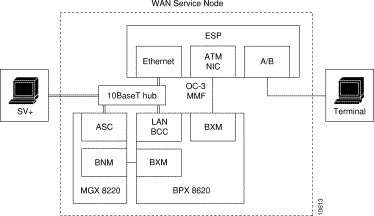
The ESP also provides the following application interfaces:
A single ESP controlling a WAN Service Node, such as is shown in Figure 10-5, operates in the StandAlone mode. In the StandAlone mode there is no redundancy for a failed ESP. During the initial installation of a ESP, it can be configured as either Primary or Secondary but must be configured to operate in StandAlone mode.
When a second ESP is added to a single ESP operating in StandAlone mode, you must change the operating mode of a StandAlone ESP to Active or Standby mode.
As shown in Figure 10-6, ESPs can be installed in redundant pairs in the WAN Service Node. In a redundant pair, one ESP is active, that is it controls the switched services in the WAN Service Node, and the other ESP is standby. The redundant ESPs are known as peers. The ESPs will switch roles from active to standby and vice versa under the following conditions:
Each ESP determines its role by means of Role Resolution protocol, which exchanges messages between the two units at startup. Both the active ESP and the standby ESP monitor its role and connectivity, and if appropriate, automatically switchover (that is, switch roles from active to Out of Service and from standby to active) with the peer ESP.
The redundant ESPs need to synchronize their database so that when the active ESP has gone out of service, the standby unit can take over and resume the service. There are two types of update mechanisms for synchronizing ESP databases. These are the bulk and real-time updates. The bulk update is used to synchronize a standby ESP with an active unit whenever it is restarted. The real-time updates are those messages that are exchanged after ESPs are synchronized and while both the active and standby ESPs are communicating.

The WAN Service Node provides another form of ESP redundancy protection through the use of Y-cables. With Y-cables, the ESP ATM NIC can be connected to two BXM cards or two BXM ports, as shown in Figure 10-7. This prevents the failure of a BXM card or port from disabling the ESP.

Figure 10-7 illustrates only a single ESP-to-BXM redundancy option. There are four ESP-to-BXM redundancy options possible:
1. A single ESP with a Y-cable to redundant BXMs.
2. Two ESPs (a redundant pair), each attached to a single port on a single BXM.
3. Two ESPs (a redundant pair), each attached to a single port on two separate (redundant) BXMs.
4. Two ESPs (a redundant pair), each attached to different ports with Y-cables on two separate (redundant) BXMs.
Y-cables are for connecting the ESP's ATM Network Interface Card to redundant BXMs. They do not necessarily indicate that the ESP is connected in the redundant pair configuration (that is, an active and standby ESP). The Cisco WAN Service Node Extended Services Processor Installation and Operation document contains further information about ESP Y cables.
As shown in Figure 10-5, the BPX switch can have an Ethernet LAN connection to a Cisco WAN Manager Workstation. Cisco WAN Manager discovers and monitors the ESP similarly to the way it does an MGX 8220 interface shelf. Cisco WAN Manager discovers the existence of the ESP when it is added to the BPX switch with the addshelf command. After discovery, the ESP will be displayed on the Cisco WAN Manager topology map as a shelf attached to the BPX switch.
Cisco WAN Manager manages the BPX switch by providing:
During provisioning, resources on all UNI ports (both ATM and Frame Relay) are partitioned between SVCs and PVCs. Partitioning is performed using the BPX switch and MGX 8220 command line interfaces. This partitioning information is retrieved from the BPX switch by reading its port and trunk tables and from the MGX 8220 by reading the resource partitioning tables in the AUSM and FRSM MIBs.
The BPX switch line and routing or feeder trunk resources to be partitioned are:
MGX 8220 Feeder Trunk (BXM/BNI) resources to be partitioned are:
MGX 8220 AUSM port resources to be partitioned are:
MGX 8220 FRSM port resources to be partitioned are:
![]()
![]()
![]()
![]()
![]()
![]()
![]()
![]()
Posted: Sun Jan 14 18:32:27 PST 2001
All contents are Copyright © 1992--2001 Cisco Systems, Inc. All rights reserved.
Important Notices and Privacy Statement.