|
|

This chapter provides a brief description of the BXM Virtual Switch Interfaces (VSIs) and some of the new features with Release 9.2. Refer to Cisco WAN Switching Command Reference for further details. Refer to 9.2 Release Notes for supported features.
The chapter contains the following:
Virtual Switch Interfaces (VSIs) allow a node to be controlled by multiple controllers such as MPLS, PNNI, and so on. These control planes can be external or internal to the switch. In this release, two VSI controllers in different control planes can independently control the switch with no communication between controllers. The controllers are essentially unaware of the existence of other control planes sharing the switch. This is possible because different control planes used different partitions of the switch resources.
When a virtual switch interface (VSI) is activated on a port, trunk, or virtual trunk for use by a master controller, such as a PNNI controller, or a MPLS Controller, the resources of the virtual interface associated with the port, trunk or virtual trunk are made available to the VSI.
A VSI controller, such as an MPLS controller, is added to a BPX switch by using the addshelf command with the VSI option. In the MPLS case, the routing protocol such as OSPF, uses the Label Distribution Protocol (LDP) to set up MPLS virtual connections (VCs) on the switch.
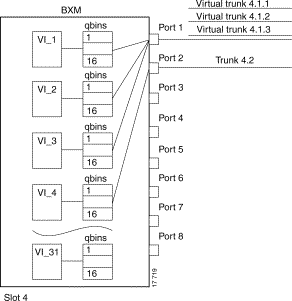
The BXM has 31 virtual interfaces that provide a number of resources including qbin buffering capability. One virtual interface is assigned to each logical trunk (physical or virtual) when the trunk is enabled. (See Figure 11-1.)
Each virtual interface has 16 qbins assigned to it. Qbins 0-9 are used for Autoroute and 10-15 are available for use by a VSI enabled on the virtual interface. (In Release 9.1, only qbin 10 was used.) The qbins 10-15 support class of service (CoS) templates on the BPX.
A virtual switch interface may be enabled on a port, trunk, or virtual trunk. The virtual switch interface is assigned the resources of the associated virtual interface.
With virtual trunking, a physical trunk can comprise a number of logical trunks called virtual trunks, and each of these virtual trunks is assigned the resources of one of the 31 virtual interfaces on a BXM (see Figure 11-1).
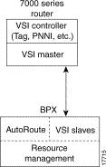
A controller application uses a VSI master to control one or more VSI slaves. For the BPX, the controller application and Master VSI reside in an external 7200 or 7500 series router and the VSI slaves are resident in BXM cards on the BPX node (see Figure 11-2).
The controller sets up the following types of connections:
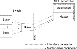
The controller establishes a link between the VSI master and every VSI slave on the associated switch. The slaves in turn establish links between each other (see Figure 11-3).
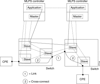
With a number of switches connected together, there are links between switches with cross connects established within the switch as shown in Figure 11-4.
The VSIs need to partition the resources between competing controllers, Autoroute, Tag, and PNNI for example. Partitioning is done with the cnfrsrc command.
Prior to this release, just one controller (of a particular type) was supported, although you could have different types of controllers splitting up a partition's assets.
The resources that need to be configured for a partition are shown in Table 11-1 for a partition designated ifci, which stands for interface controller 1 in this instance. The three parameters that need to be distributed are the number of logical connections (lcns), bandwidth (bw), and virtual path ids (vpi).
| ifci parameters | Min | Max |
|---|---|---|
lcns | min_lcnsi | max_lcnsi |
bw | min_bwi | max_bwi |
vpi | min_vpi | max_vpi |
The controller is supplied with a logical lcn connection number, that is slot, port, etc., information that is converted to a logical connection number (lcn).
Some ranges of values available for a partition are listed in Table 11-2:
| Range | |
|---|---|
trunks | 1-4095 VPI range |
ports | 1-4095 VPI range |
virtual trunk | only one VPI available per virtual trunk since a virtual trunk is currently delineated by a specific VP |
virtual trunk | each virtual trunk can either be Autoroute or VSI, not both |
When a trunk is added, the entire bandwidth is allocated to Autoroute. To change the allocation in order to provide resources for a vsi, the cnfrsrc command is used on the BPX switch. A view of the resource partitioning available is shown in Figure 11-5.
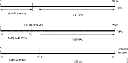
In this release, you can configure partition resources between Automatic Routing Management PVCs and two VSI controllers (LSC or PNNI). Two VSI controllers in different control planes can independently control the switch with no communication between controllers. The controllers are essentially unaware of the existence of other control planes sharing the switch. This is possible because different control planes used different partitions of the switch resources.
You can add one or more redundant LSC controllers to one partition, and one or more redundant PNNI controllers to the other partition. In this release, two new templates have been added for interfaces with multiple partitions controlled simultaneously by a PNNI controller and an LSC.
The master redundancy feature allows multiple controllers to control the same partition. In a multiple partition environment, master redundancy is independently supported on each partition.
These limitations apply to multiple VSI partitioning:
Only one controller can be added to a BPX interface. Different controllers must be added to different switch interfaces.
For more information on multiple VSI partitioning, see the chapter on "VSI Commands" in the Cisco WAN Switching Command Reference, Release 9.2.30.
Class of Service Templates (COS Templates) provide a means of mapping a set of standard connection protocol parameters to "extended" platform specific parameters. Full QoS implies that each VC is served through one of a number of Class of Service buffers (qbins) which are differentiated by their QoS characteristics.
When you activate an interface with an uptrk or upport command, a default service template is automatically assigned to that interface. The corresponding qbin templates are simultaneously set up in the BXM's data structure.
The service class template provides a means of mapping a set of extended parameters, which are generally platform specific, based on the set of standard ATM parameters passed to the VSI slave during connection setup.
A set of service templates is stored in each switch (for example, BPX) and downloaded to the service modules (for example, BXMs) as needed.
The service templates contains two classes of data. One class consists of parameters necessary to establish a connection (that is, per VC) and includes entries such as UPC actions, various bandwidth- related items, per VC thresholds, and so on. The second class of data items includes those necessary to configure the associated class of service buffers (qbins) that provide QoS support.
The general types of parameters passed from a VSI Master to a Slave include:
Each VC added by a VSI master is assigned to a specific service class by means of a 32-bit service type identifier. Current identifiers are for:
When a connection setup request is received from the VSI master in the Label Switch Controller, the VSI slave (in the BXM, for example) uses the service type identifier to index into a Service Class Template database containing extended parameter settings for connections matching that index. The slave uses these values to complete the connection setup and program the hardware.
One of the parameters specified for each service type is the particular BXM class of service buffer (qbin) to use. The qbin buffers provide separation of service type to match the QoS requirements.
Service templates on the BPX are maintained by the BCC and are downloaded to the BXM cards as part of the card configuration process as a result of card activation, rebuild, or switchover. In Release 9.2 the templates are non-configurable.
There are three service types of templates, and the user can assign any one of the templates to a virtual switch interface. (See Figure 11-6.)
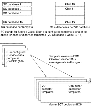
When the upport or uptrk command is used to activate an interface on the BXM card, the default service template, which is MPLS1, is assigned to the interface. This service template has an indentifier of "1". The service template assigned to an interface can be changed with the cnfvsiif command. This can be done only when there are no active VSI connections on the BXM. The templates can be displayed with the dspvsiif command.
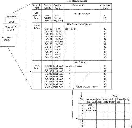
Each template table row includes an entry that defines the qbin to be used for that class of service (see Figure 11-7). This mapping defines a relationship between the template and the interface qbin's configuration.
A qbin template defines a default configuration for the set of qbins for the logical interface. When a template assignment is made to an interface, the corresponding default qbin configuration becomes the interface's qbin configuration. Some of the parameters of the interface's qbin configuration can be changed on a per-interface basis. Such changes affect only that interface's qbin configuration and no others, and do not affect the qbin templates.
Qbin templates are used only with qbins that are available to VSI partitions, namely qbins 10 through 15. Qbins 10 through 15 are used by the VSI on interfaces configured as trunks or ports. The rest of the qbins (0-9) are reserved for and configured by Autoroute.
Service templates are downloaded to a card (BXM) under the following conditions:
A default service template is assigned to a logical interface (VI) when the interface is upped via upport/uptrk.
For example:
This default template has the identifier of 1. Users can change the service template from service template 1 to another service template using the cnfvsiif command.
The cnfvsiif command is used to assign a selected service template to an interface (VI) by specifying the template number. It has the following syntax:
cnfvsiif <slot.port.vtrk> <tmplt_id>
For example:
The dspvsiif command is used to display the type of service template assigned to an interface (VI). It has the following syntax:
dspvsiif <slot.port.vtrk>
When an interface (VI) is activated by uptrk or upport, the default service template is assigned to the interface (VI). The corresponding qbin template is then copied into the card's (BXM) data structure of that interface. A user can change some of the qbin parameters using the cnfqbin command. The qbin is now "user configured" as opposed to "template configured". This information may be viewed on the dspqbin screen.
The available qbin parameters are shown in Table 11-3. Notice that the qbins available for VSI are restricted to qbins 10-15 for that interface. All 31 possible virtual interfaces are each provided with 16 qbins.
| Template Object Name | Template Units | Template Range/Values |
|---|---|---|
QBIN Number | enumeration | 0 -15 (10-15 valid for VSI) |
Max QBIN Threshold | u sec | 1-2000000 |
QBIN CLP High Threshold | % of max Qbin threshold | 0 - 100 |
QBIN CLP Low Threshold | % of max Qbin threshold | 0 - 100 |
EFCI Threshold | % of max Qbin threshold | 0 - 100 |
Discard Selection | enumeration | 1 - CLP Hystersis 2 - Frame Discard |
Weighted Fair Queueing | enable/disable | 0: Disable 1: Enable |
Additional service template commands are:
dspsct: This command is used to display the template number assigned to an interface. The command has three levels of operation:
dspqbintmt: Displays the qbin templates.
The service-type parameter for a connection is specified in the connection bandwidth information parameter group. The service-type and service-category parameters determine the service class to be used from the service template.
When a connection request is received by the VSI Slave, it is first subjected to a Connection Admission Control (CAC) process before being forwarded to the FW layer responsible for actually programming the connection. The connection is granted based on the following criteria:
LCNs available in the VSI partition
QoS guarantees
When the VSI slave accepts (that is, after CAC) a connection setup command from the VSI master in the MPLS Controller, it receives information about the connection including service type, bandwidth parameters, and QoS parameters. This information is used to determine an index into the VI's selected Service Template's VC Descriptor table thereby establishing access to the associated extended parameter set stored in the table.
The service type identifier is a 32-bit number. In this release, there are three service types: VSI Special Type, ATMF Types, and MPLS types, as shown in Table 11-4.
| Template Type | Service Type Identifiers | Service Types | Associated Qbin |
|---|---|---|---|
VSI Special Types | 0x0000 0x0001 0x0002 | Null Default Signaling | - 13 10 |
ATMF Types | 0x0100 0x0101 0x0102 0x0103 0x0104 0x0105 0x0106 0x0107 0x0108 0x0109 0x010A 0x010B | CBR.1 VBR.1-RT VBR.2-RT VBR.3-RT VBR.1-nRT VBR.2-nRT VBR.3-nRT UBR.1 UBR.2 ABR CBR.2 CBR.3 | 10 11 11 11 12 12 12 13 13 14 10 10 |
MPLS Types | 0x0200 0x0201 0x0202 0x0203 0x0204 0x0205 0x0206 0x0207 0x0210 | label cos0, per-class service label cos1, per-class service label cos2, per-class service label cos3, per-class service label cos4, per-class service label cos5, per-class service label cos6, per-class service label cos7, per-class service label ABR, (Tag w/ ABR flow control) | 10 11 12 13 10 11 12 13 14 |
A summary of the parameters associated with each of the service templates is provided in Table 11-5 through Table 11-8. Table 11-9 provides a description of these parameters and also the range of values that may be configured if the template does not assign an arbitrary value.
Table 11-5 lists the parameters associated with Default (0x0001) and Signaling (0x0002) service template categories.
| Parameter | VSI Default (0x0001) | VSI Signalling (0x0002) |
|---|---|---|
QBIN Number | 10 | 15 |
UPC Enable | 0 | * |
UPC CLP Selection | 0 | * |
Policing Action (GCRA #1) | 0 | * |
Policing Action (GCRA #2) | 0 | * |
PCR | - | 300 kbps |
MCR | - | 300 kbps |
SCR | - | - |
ICR | - | - |
MBS | - | - |
CoS Min BW | 0 | * |
CoS Max BW | 0 | * |
Scaling Class | 3 | 3 |
CAC Treatment ID | 1 | 1 |
VC Max Threshold | Q_max/4 | * |
VC CLPhi Threshold | 75 | * |
VC CLPlo Threshold | 30 | * |
VC EPD Threshold | 90 | * |
VC EFCI Threshold | 60 | * |
VC Discard Selection | 0 | * |
Table 11-6 and Table 11-7 lists the parameters associated with the PNNI service templates.
| Parameter | CBR.1 | CBR.2 | CBR.3 | UBR.1 | UBR.2 | ABR |
|---|---|---|---|---|---|---|
QBIN Number | 10 | 10 | 10 | 13 | 13 | 14 |
UPC Enable | 1 | 1 | 1 | 1 | 1 | 1 |
UPC CLP Selection | * | * | * | * | * | * |
Policing Action (GCRA #1) | * | * | * | * | * | * |
Policing Action (GCRA #2) | * | * | * | * | * | * |
PCR |
|
|
|
|
|
|
MCR | - | - | - | * | * | * |
SCR | - | - | - | 50 | 50 | * |
ICR | - | - | - | - | - | * |
MBS | - | - | - | - | - | * |
CoS Min BW | 0 | 0 | 0 | 0 | 0 | 0 |
CoS Max BW | 100 | 100 | 100 | 100 | 100 | 100 |
Scaling Class | * | * | * | * | * | * |
CAC Treatment ID | * | * | * | * | * | * |
VC Max Threshold | * | * | * | * | * | * |
VC CLPhi Threshold | * | * | * | * | * | * |
VC CLPlo Threshold | * | * | * | * | * | * |
VC EPD Threshold | * | * | * | * | * | * |
VC EFCI Threshold | * | * | * | * | * | * |
VC Discard Selection | * | * | * | * | * | * |
VSVD/FCES | - | - | - | - | - | * |
ADTF | - | - | - | - | - | 500 |
RDF | - | - | - | - | - | 16 |
RIF | - | - | - | - | - | 16 |
NRM | - | - | - | - | - | 32 |
TRM | - | - | - | - | - | 0 |
CDF |
|
|
|
|
| 16 |
TBE | - | - | - | - | - | 16777215 |
FRTT | - | - | - | - | - | * |
| Parameter | VBRrt.1 | VBRrt.2 | VBRrt.3 | VBRnrt.1 | VBRnrt.2 | VBRnrt.3 |
|---|---|---|---|---|---|---|
QBIN Number | 11 | 11 | 11 | 12 | 12 | 12 |
UPC Enable | 1 | 1 | 1 | 1 | 1 | 1 |
UPC CLP Selection | * | * | * | * | * | * |
Policing Action (GCRA #1) | * | * | * | * | * | * |
Policing Action (GCRA #2) | * | * | * | * | * | * |
PCR |
|
|
|
|
|
|
MCR | * | * | * | * | * | * |
SCR | * | * | * | * | * | * |
ICR | - | - | - | - | - | - |
MBS | * | * | * | * | * | * |
CoS Min BW | 0 | 0 | 0 | 0 | 0 | 0 |
CoS Max BW | 100 | 100 | 100 | 100 | 100 | 100 |
Scaling Class | * | * | * | * | * | * |
CAC Treatment ID | * | * | * | * | * | * |
VC Max Threshold | * | * | * | * | * | * |
VC CLPhi Threshold | * | * | * | * | * | * |
VC CLPlo Threshold | * | * | * | * | * | * |
VC EPD Threshold | * | * | * | * | * | * |
VC EFCI Threshold | * | * | * | * | * | * |
VC Discard Selection | * | * | * | * | * | * |
* indicates not applicable
Table 11-8 lists the connection parameters and their default values for label switching service templates.
| Parameter | CoS 0/4 | CoS 1/5 | CoS 2/6 | CoS 3/7 | Tag-ABR |
|---|---|---|---|---|---|
Qbin # | 10 | 11 | 12 | 13 | 14 |
UPC Enable | 0 | 0 | 0 | 0 | 0 |
UPC CLP Selection | 0 | 0 | 0 | 0 | 0 |
Policing Action (GCRA #1) | 0 | 0 | 0 | 0 | 0 |
Policing Action (GCRA#2) | 0 | 0 | 0 | 0 | 0 |
PCR | - | - | - | - | cr/10 |
MCR | - | - | - | - | 0 |
SCR | - | - | - | - | P_max |
ICR | - | - | - | - | 100 |
MBS | - | - | - | - | - |
CoS Min BW | 0 | 0 | 0 | 0 | 0 |
CoS Max BW | 0 | 0 | 0 | 0 | 100 |
Scaling Class | 3 | 3 | 2 | 1 | 2 |
CAC Treatment | 1 | 1 | 1 | 1 | 1 |
VC Max | Q_max/4 | Q_max/4 | Q_max/4 | Q_max/4 | cr/200ms |
VC CLPhi | 75 | 75 | 75 | 75 | 75 |
VC CLPlo | 30 | 30 | 30 | 30 | 30 |
VC EPD | 90 | 90 | 90 | 90 | 90 |
VC EFCI | 60 | 60 | 60 | 60 | 30 |
VC Discard Selection | 0 | 0 | 0 | 0 | 0 |
VSVD/FCES | - | - | - | - | 0 |
ADTF | - | - | - | - | 500 |
RDF | - | - | - | - | 16 |
RIF | - | - | - | - | 16 |
NRM | - | - | - | - | 32 |
TRM | - | - | - | - | 0 |
CDF | - | - | - | - | 16 |
TBE | - | - | - | - | 16777215 |
FRTT | - | - | - | - | 0 |
Table 11-9 describes the connection parameters that are listed in the preceding tables and also lists the range of values that may be configured, if not pre-configured.
Every service class does not include all parameters listed in Table 11-9 below. For example, a CBR service type have fewer parameters than an ABR service type.
| Object Name | Range/Values | Template Units |
|---|---|---|
QBIN Number | 10 - 15 | qbin # |
Scaling Class | 0 - 3 | enumeration |
CDVT | 0 - 5M (5 sec) | secs |
MBS | 1 - 5M | cells |
ICR | MCR - PCR | cells |
MCR | 50 - LR | cells |
SCR | MCR - LineRate | cells |
UPC Enable | 0 - Disable GCRAs 1 - Enabled GCRAs 2 - Enable GCRA #1 3 - Enable GCRA #2 | enumeration |
UPC CLP Selection | 0 - Bk 1: CLP (0+1) Bk 2: CLP (0) 1 - Bk 1: CLP (0+1) Bk 2: CLP (0+1) 2 - Bk 1: CLP (0+1) Bk 2: Disabled | enumeration |
Policing Action (GCRA #1) | 0 - Discard 1 - Set CLP bit 2 - Set CLP of untagged cells, disc. tag'd cells | enumeration |
Policing Action (GCRA #2) | 0 - Discard 1 - Set CLP bit 2 - Set CLP of untagged cells, disc. tag'd cells | enumeration |
VC Max |
| cells |
CLP Lo | 0 - 100 | %Vc Max |
CLP Hi | 0 - 100 | %Vc Max |
EFCI | 0 - 100 | %Vc Max |
VC Discard Threshold Selection | 0 - CLP Hysteresis 1 - EPD | enumeration |
VSVD | 0: None 1: VSVD 2: VSVD w / external Segment | enumeration |
Reduced Format ADTF | 0 - 7 | enumeration |
Reduced Format Rate Decrease Factor (RRDF) | 1 - 15 | enumeration |
Reduced Format Rate Increase Factor (RRIF) | 1 - 15 | enumeration |
Reduced Format Time Between Fwd RM cells (RTrm) | 0 - 7 | enumeration |
Cut-Off Number of RM Cells (CRM) | 1 - 4095 | cells |
The qbin default settings are shown in Table 11-10. The Service Class Template default settings for Label Switch Controllers and PNNI controllers are shown in Table 11-11
Note: Templates 2, 4, 6, and 8 add support for policing on PPD.
| QBIN | Max Qbin Threshold (usec) | CLP High | CLP Low/EPD | EFCI | Discard Selection |
|---|---|---|---|---|---|
| LABEL Template 1 | |||||
10 (Null, Default, Signalling, Tag0,4) | 300,000 | 100% | 95% | 100% | EPD |
11 (Tag1,5) | 300,000 | 100% | 95% | 100% | EPD |
12 (Tag2,6) | 300,000 | 100% | 95% | 100% | EPD |
13 (Tag3,7) | 300,000 | 100% | 95% | 100% | EPD |
14 (Tag Abr) | 300,000 | 100% | 95% | 6% | EPD |
15 (Tag unused) | 300,000 | 100% | 95% | 100% | EPD |
| PNNI Templates 2 (with policing) and 3 | |||||
10 (Null, Default, CBR) | 4200 | 80% | 60% | 100% | CLP |
11 (VbrRt) | 53000 | 80% | 60% | 100% | EPD |
12 (VbrNrt) | 53000 | 80% | 60% | 100% | EPD |
13 (Ubr) | 105000 | 80% | 60% | 100% | EPD |
14 (Abr) | 105000 | 80% | 60% | 20% | EPD |
15 (Unused) | 105000 | 80% | 60% | 100% | EPD |
| Full Support for ATMF and reduced support for Tag CoS without Tag-Abr Templates 4 (with policing) and 5 | |||||
10 (Tag 0,4,1,5, Default, UBR, Tag-Abr*) | 300,000 | 100% | 95% | 100% | EPD |
11 (VbrRt) | 53000 | 80% | 60% | 100% | EPD |
12 (VbrNrt) | 53000 | 80% | 60% | 100% | EPD |
13 (Tag 2,6,3,7) | 300,000 | 100% | 95% | 100% | EPD |
14 (Abr) | 105000 | 80% | 60% | 20% | EPD |
15 (Cbr) | 4200 | 80% | 60% | 100% | CLP |
| Full Support for Tag ABR and ATMF without Tag CoS Templates 6 (with policing) and 7 | |||||
10 (Tag 0,4,1,5,2,6,3,7 Default, UBR) | 300,000 | 100% | 95% | 100% | EPD |
11 (VbrRt) | 53000 | 80% | 60% | 100% | EPD |
12 (VbrNrt) | 53000 | 80% | 60% | 100% | EPD |
13 (Tag-Abr) | 300,000 | 100% | 95% | 6% | EPD |
14 (Abr) | 105000 | 80% | 60% | 20% | EPD |
15 (Cbr) | 4200 | 80% | 60% | 100% | CLP |
| Full Support for Tag CoS and reduced support for ATMF Templates 8 (with policing) and 9 | |||||
10 (Cbr, Vbr-rt) | 4200 | 80% | 60% | 100% | CLP |
11 (Vbr-nrt, Abr) | 53000 | 80% | 60% | 20% | EPD |
12 (Ubr, Tag 0,4) | 300,000 | 100% | 95% | 100% | EPD |
13 (Tag 1, 5, Tag-Abr) | 300,000 | 100% | 95% | 6% | EPD |
14 (Tag 2,6) | 300,000 | 100% | 95% | 100% | EPD |
15 (Tag 3, 7) | 300,000 | 100% | 95% | 100% | EPD |
| PARAMETER WITH DEFAULT SETTING | LABEL | PNNI |
|---|---|---|
MCR | Tag0-7: N/A | Abr: 0% |
AAL5 Frame Base Traffic Control (Discard Selection) | EPD | Hystersis |
CDVT(0+1) | 250,000 | 250,000 |
VSVD | Tag0-7: N/A | Abr: None |
SCR | Tag0-7: N/A | Vbr: 100% |
MBS | Tag0-7: N/A | Vbr: 1000 |
Policing | Policing Disable | VbrRt1: VbrRt2: VbrRt3: VbrNRt1: VbrNRt2: VbrNRt3: Ubr1: Ubr2: Abr: Cbr1: Cbr2: Cbr3: |
ICR | Tag0-7: N/A | Abr: 0% |
ADTF | Tag0-7: N/A | Abr: 1000 msec |
Trm | Tag0-7: N/A | Abr: 100 |
VC Qdepth | 61440 | 10,000 |
CLP Hi | 100 | 80 |
CLP Lo / EPD | 40 | 35 |
EFCI | TagABR: 20 | 20 (not valid for non-ABR) |
RIF | Tag0-7: N/A | Abr: 16 |
RDF | Tag0-7: N/A | Abr: 16 |
Nrm | Tag0-7: N/A | Abr: 32 |
FRTT | Tag0-7: N/A | Abr: 0 |
TBE | Tag0-7: N/A | Abr: 16,777,215
|
IBS | N/A | N/A |
CAC Treatment | LCN | vbr: CAC4 |
Scaling Class | UBR - Scaled 1st | Vbr: VBR -Scaled 3rd |
CDF | 16 | 16 |
![]()
![]()
![]()
![]()
![]()
![]()
![]()
![]()
Posted: Sun Jan 14 18:36:28 PST 2001
All contents are Copyright © 1992--2001 Cisco Systems, Inc. All rights reserved.
Important Notices and Privacy Statement.