|
|

This chapter explains how to install the AC power supply tray, power supplies, and make AC power connections.
Before proceeding to this chapter, the procedures should be completed, in either:
This chapter contains the following sections:
All AC-powered systems are required to use a set of rear support brackets to provide additional support for the rear of the Power Supply Tray. To install the AC Power Supply Tray proceed as follows:
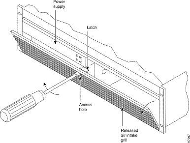
Step 2 Locate the small access hole in the top center of the front Air Intake Grille on the Power Supply Tray (Figure 6-3).
Step 3 Insert a slotted blade screwdriver (0.20/0.25 inch blade width) into the access hole until it stops (approximately 1 inch).
Step 4 Carefully rotate the screwdriver approximately a quarter turn in either direction. The top of the Air Intake Grille should spring out.
Step 5 Remove the Air Intake Grille.
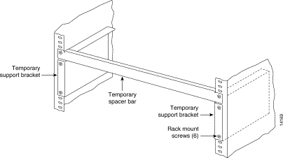
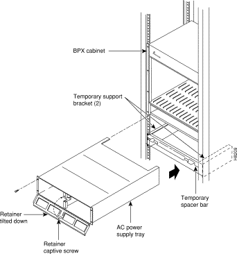
Step 6 Slide the Power Supply Tray in the rack between the BPX shelf and the temporary support brackets and spacer bar (Figure 6-2). If cables are attached, use care to avoid damaging them.
Step 7 Install screws and washers to loosely secure power supply assembly to the front of the BPX shelf. Align the front flanges of the Power Supply Tray with the flanges on the BPX shelf and tighten screws. There should be approximately 1/16" clearance between the BPX shelf and the Power Supply Tray to provide sufficient clearance for inserting power supplies.
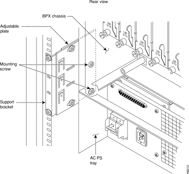
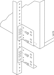
Step 8 Secure the Power Supply Tray to the rear support bracket (plate) using one #10-32 screw and flat washer on each side. Use the lower hole in the brackets. Figure 6-4 shows the setup for a configuration with the vertical rails at a 30 inch setback.
For a configuration with vertical rails at a 19.86 inch rail setback, attach one #10-32 screw and flat washer to the single bracket on each side. Use the lower hole in the brackets. Figure 6-5 shows the bracket configuration only; the power supply tray position is the same as shown for in Figure 6-4.
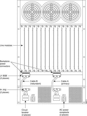
Step 9 Connect and secure a power supply interconnect cable (Cable A in Figure 6-6) between the primary AC Power Supply and the BPX backplane power connector.
Step 10 Connect and secure a second power supply interconnect cable (Cable B in Figure 6-6) between the redundant AC Power Supply and the BPX backplane power connector.
Step 11 Remove the temporary support bracket and spacer bracket from the front of the cabinet.
The AC Power Supply is an assembly consisting of an AC-DC Converter, cooling fan, LED bezel, and mounting frame. The AC Power Supply is installed and removed as an integral unit. There may be one or two AC Power Supplies depending on node configuration. They are housed in the Power Supply Tray.
Proceed as follows to remove and reinstall an AC Power Supply in the Power Supply Tray:
Step 2 Set the circuit breaker(s) at the rear of the Power Supply Tray to OFF.
Step 3 If not already removed, remove the Power Supply Tray front Air Intake Grille. Locate the small access hole in the top, center of the front Air Intake Grille for the Power Supply Tray (Figure 6-7).

Step 4 Insert a small slotted blade screwdriver (0.20/0.25 inch blade width) into the access hole until it stops, approximately 1 inch (2.5 cm).
Step 5 Carefully rotate the screwdriver approximately a quarter turn in either direction. The top of the Air Intake Grille should spring out.
Step 6 Loosen the captive screw in the center of the power supply retainer and rotate the hinged retainer frame down (Figure 6-7).
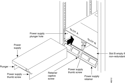
Step 7 Align the power supply in the PS-A slots at the bottom of the Power Supply Tray and gently slide it in part way (Figure 6-8).
Step 8 Continue to slide the power supply in until it mates with the rear connector.
Step 9 When the power supply is completely seated in its connector, the pin plunger on the left side of the supply will engage with a hole in the tray. If not, push firmly on the front edge until the power supply assembly seats in the connector.
Step 10 Screw the right-hand thumbscrew in finger tight.
Step 11 When a second power supply is provided, install it in the PS-B slot in the same manner after removing the Blank Panel from Slot B.
Step 12 Rotate the power supply retainer up and tighten the center captive screw.
Step 13 Install the Air Intake Grille. Press on the top center until the latch snaps into place.
There are three configurations of the AC-powered BPX cabinet as follows:
An 8 ft. (3 m.) power cord is supplied with each AC Power Supply Assembly. To make AC power connections to the BPX:
Step 2 Plug the BPX cord into a 220 to 240 VAC, single-phase, wall outlet capable of supplying 15A. The building circuit should be protected with a 20A circuit breaker.
Step 3 For the dual power feed version, plug each power cord into receptacles on separate building circuits to provide protection against a power feed failure. Each building circuit should be protected with a 20A circuit breaker.
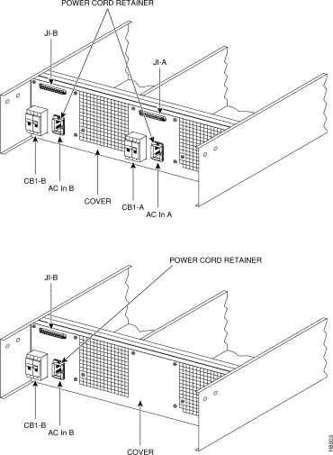
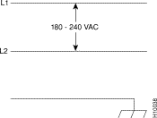
Step 4 The ground (green/yellow) wire of the AC power cord provides the safety ground to the BPX via the grounding prong on the three-prong connectors. Make sure the building AC receptacle is also properly grounded (Figure 6-10).
.
Step 5 As applicable, provide a convenience AC outlet strip, with at least four outlets, near the BPX node to power optional modems, CSU, or DSUs, test equipment, etc. There is no accessory AC outlet supplied on the BPX. This outlet strip should be connected to a source of AC voltage normal for the region (e.g., 115 VAC for domestic US use).
Step 6 Proceed to Chapter 7, Finishing the Installation.
Refer to the BPX Service Node Reference document, Repair and Replacement chapter, for instructions on replacement of these fuses, and contact Customer Service for assistance regarding their replacement.
 | Caution For continued protection against risk of fire, replace only with the same type and rating of fuse. Fuses should only be replaced after all power to the BPX has been turned off. |
Fan fuses are located on the backplane of the BPX to protect against catastrophic backplane damage in the event of a shorted fan cable. Backplane fuses should rarely, if ever, need replacement. The fuses are designated F1 through F3, corresponding to fans 1 through 3.
 | Caution Refer to the BPX Service Node Reference document, Repair and Replacement chapter, for instructions on replacement of these fuses, and contact Customer Service for assistance regarding their replacement. |
 | Caution For continued protection against risk of fire, replace only with the same type and rating of fuse. Replace fuses only after all power to the BPX has been turned off. |
![]()
![]()
![]()
![]()
![]()
![]()
![]()
![]()
Posted: Thu Jan 18 01:20:46 PST 2001
All contents are Copyright © 1992--2001 Cisco Systems, Inc. All rights reserved.
Important Notices and Privacy Statement.