|
|

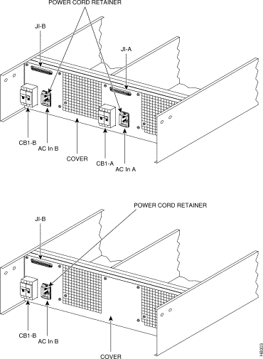
Refer to "AC Power Input Connections" and "DC Power Input Connections" sections which provide information on making connections to the AC and DC Power Supply Assemblies for BPX nodes.
There are three configurations of the AC-powered BPX cabinet as follows:
An 8 ft. (3 m.) power cord is supplied with each AC Power Supply Assembly. To make AC power connections to the BPX:
Step 2 Plug the BPX cord into a 220 to 240 VAC, single-phase, wall outlet capable of supplying 15A. The building circuit should be protected with a 20A circuit breaker.
Step 3 For the dual power feed version, plug each power cord into receptacles on separate building circuits to provide protection against a power feed failure. Each building circuit should be protected with a 20A circuit breaker.
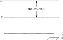
Step 4 The ground (green/yellow) wire of the AC power cord provides the safety ground to the BPX via the grounding prong on the three-prong connectors. Make sure the building AC receptacle is also properly grounded (Figure 2-19)
.
Step 5 As applicable, provide a convenience AC outlet strip, with at least four outlets, near the BPX node to power optional modems, CSU, or DSUs, test equipment, etc. There is no accessory AC outlet supplied on the BPX. This outlet strip should be connected to a source of AC voltage normal for the region (e.g., 115 VAC for domestic US use).
There are two versions of the DC-powered BPX cabinet as follows:
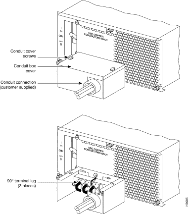
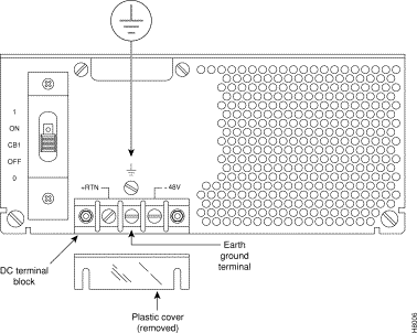
For DC systems, the wiring is connected from a 48 VDC power source to one or two DC Power Entry Module(s). This wiring is provided by the installer. A metallic conduit box that meets all electrical codes for attaching electrical conduit is factory-installed Figure 2-20. A simple plastic cover is also enclosed for customers who do not require conduit protection for the input power leads Figure 2-21. Use conduit if required by local electrical code.
To make DC power connections to the BPX:
Step 2 Determine which knockout to remove (rear or bottom). Remove knockout and install conduit fitting.
Step 3 If conduit is not required, remove the conduit box by removing the two screws, one above the terminal block and one below it.
Step 4 Run three wires from the DC terminal block to a source of 48 VDC. Use 8 AWG wire (or metric equivalent for E1 systems). Use a #10 screw ring lug designed for 8 AWG wire (90º lug if using conduit box) to terminate the wires.
Step 5 Remember that this is a positive ground system. Connect the positive lead to the +RTN terminal. Connect the negative lead to the -48V terminal. Connect the earth ground to the middle, terminal labeled SAFETY GROUND. See Figure 2-20 and Figure 2-21.
 | Warning For personnel safety, the green/yellow wire must be connected to safety (earth) ground at both the equipment and at the supply side of the dc wiring. |
Step 6 Terminate the DC input wiring to a DC source capable of supplying at least 40 amperes. A 40A dc circuit breaker is required at the 48 VDC facility power source. An easily accessible disconnect device should be incorporated into the facility wiring. Be sure to connect the ground wire/conduit to a solid office (earth) ground.
Step 7 If the system is equipped with dual power feed, repeat steps 3 through 5 for the second power feed.
Step 8 Either replace the cover on the conduit terminating box or attach the plastic cover plate to the terminal block with screws into the two terminal block standoffs. See Figure 2-20 and Figure 2-21.
Refer to the BPX Reference Manual, "Repair and Replacement" chapter, for instructions on replacement of these fuses, and contact Cisco Customer Service for assistance regarding their replacement.
 | Caution For continued protection against risk of fire, replace only with the same type and rating of fuse. Fuses should only be replaced after all power to the BPX has been turned off. |
Fan fuses are located on the backplane of the BPX to protect against catastrophic backplane damage in the event of a shorted fan cable. Backplane fuses should rarely, if ever, need replacement. The fuses are designated F1 through F3, corresponding to fans 1 through 3.
 | Caution Refer to the BPX Reference Manual, "Repair and Replacement" chapter, for instructions on replacement of these fuses, and contact Cisco Customer Service for assistance regarding their replacement. |
 | Caution For continued protection against risk of fire, replace only with the same type and rating of fuse. Replace fuses only after all power to the BPX has been turned off. |
 | Caution Ground yourself before handling BPX cards by placing a wrist strap on your wrist and clipping the strap lead to the cabinet, or use the wrist strap that is connected to the cabinet. |
The card shelf in the BPX has card slots numbered from 1 to 15, as viewed from left to right from the front of the cabinet. Front and rear views of the BPX card shelf are shown in Figure 2-22 and Figure 2-23. The configuration rules for the BPX are summarized as follows.
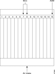
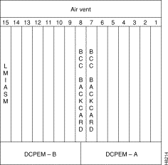
 | Caution Ground yourself before handling BPX cards by placing a wrist strap on your wrist and clipping the strap lead to the cabinet, or use the wrist strap that is connected to the cabinet. |
 | Caution Blank Front Card and Rear Face Plates must be used to fill/cover empty card slots to eliminate Radio Frequency Interference (RFI) and Electromagnetic Interference (EMI) and to ensure correct air flow through the card cage. |
Systems may be shipped with empty shelves, with filler cards or with plug-in cards installed. If filler cards are installed in each slot, some of them may need to be replaced with functional cards. The front cards are held captive mechanically by the Air Intake Grille and can not be removed until the lower Air Intake Grille is released.
 | Caution Do not attempt to remove a front card from the BPX cabinet until the Air Intake Grille is released and lowered or the Air Intake Grille and/or card extractors may be damaged. |
Proceed as follows to remove/install a front card.
 | Caution Before any card is installed, always examine the backplane and card cage guides for any signs of loose or misplaced EMI gasketing. Examine the backplane connectors for bent or damaged connection or pre-power pins. |
Step 2 Locate the small access hole in the top center of the front Air Intake Grille below the card slots (see Figure 2-24 for location).
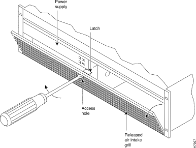
Step 3 Insert a small slotted blade screwdriver (0.20/0.25 inch blade width) into the access hole until it stops (approximately 1 inch).
Step 4 Carefully rotate the screwdriver approximately a quarter turn in either direction. The top of the Air Intake Grille should spring out.
Step 5 Remove Air Intake Grille.
Step 6 To remove a card, rotate the extractor handles at the top and bottom of the card to release the card and slide it out.
Step 7 To insert a new card, position the rear card guides over the appropriate slots at the top and bottom of the card cage.
Step 8 Gently slide the card in all the way to the rear of the slot and seat the board by fully seating both extractor handles. The handles should snap back to a vertical position when seated.
 | Caution Ground yourself before handling BPX cards by placing a wrist strap on your wrist and clipping the strap lead to the cabinet, or use the wrist strap that is connected to the cabinet. |
Proceed as follows to install a back cards including line modules.
Step 2 For existing installations, remove any cable(s) that may be attached and tag them so they may be replaced in the same location.
Step 3 Loosen the captive mounting screws on both top and bottom of the line module faceplate with a slotted blade screwdriver (Figure 2-25)
Step 4 Lift the extractor handles at the top and bottom, and slide out the line module.
Step 5 To re-insert the line module, locate the corner edges of the card into the appropriate guide slots at the top and bottom of the card cage. Gently slide the card in all the way to the rear of the slot and push to seat the card in the connector.
Step 6 Screw in the captive screws.
Step 7 Replace any cables that may have been removed in step 2.
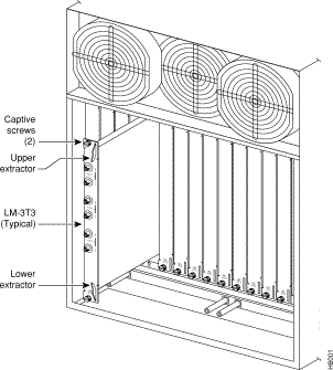
Each LM-3T3 and LM-3E3 line module (BNI backcard) provides three ports with a BNC connector each for the XMT trunk output and for the RCV trunk input. Each LM-2T3 and LM-2E3 line module (ASI backcard) provides two ports with a BNC connector each for the XMT line output.and for the RCV line input.Make the T3/E3 connections to each port as follows.
Step 2 The BPX has tie-downs inside the cabinet to hold cabling in place. Pull them apart as applicable, place the routed cable in position, wrap the ties around the cable and remake the loops by pressing the two sections together.
Step 3 Connect the cables to the BNC connectors on the LM-3T3 or LM-3E3 line modules. Remember, the RCV is an input to the BPX and XMT is an output from the BPX. The ports are numbered from top to bottom as indicated in Figure 2-26.
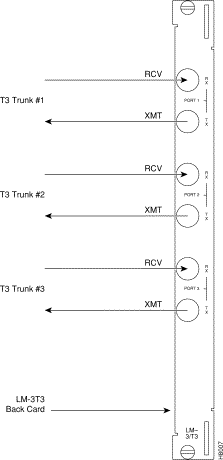
Step 4 Record which slot and port number are used for each trunk or line. You'll need the information later when configuring the network.
Step 5 If optional Y-cable redundancy is desired, locate a 3-way BNC Y-cable adapter for each port to be so equipped. As an alternative to the Y-cable, use a BNC "T" and two short BNC-BNC cables.
Step 6 For card redundancy, make sure there are two appropriate line modules equipped in adjacent slots.
Step 7 Connect two legs of the Y-cable to the XMT T3 or E3 connectors on the same port on each of the two line modules (Figure 2-27). Do the same with the two RCV T3 or E3 connectors.
Step 8 Connect the third leg of the XMT and RCV Y-cable adapters to the XMT and RCV trunk cable.
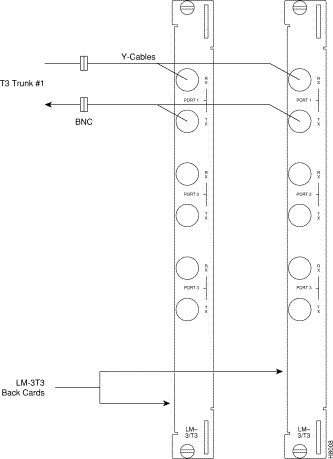
Step 2 The BPX has tie-downs inside the cabinet to hold cabling in place. Pull them apart as applicable, place the routed cable in position, wrap the ties around the cable and remake the loops by pressing the two sections together.
Step 3 Connect the cables to the applicable connectors on the OC3 line modules. Remember, the RCV is an input to the BPX and XMT is an output from the BPX. The ports are numbered from top to bottom as indicated in Figure 2-28.
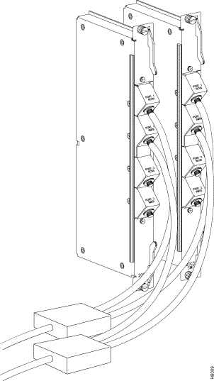
Step 4 Record which slot and port number are used for each trunk or line. You'll need the information later when configuring the network.
Step 5 A Y-Cable redundancy connection for the SMF-2-BC backcard is shown in Figure 2-28. Y-Cable redundancy is supported only for the SMF-2-BC backcard which is used with either the BNI-155 or the ASI-155.
Step 6 For card redundancy, make sure there are two appropriate line modules equipped in adjacent slots.
Step 7 Connect two legs of the Y-cable to the XMT connectors on the same port on each of the two line modules (Figure 2-28). Do the same with the two RCV connectors.
Dry contact relay closures are available for forwarding BPX system alarms to a user office alarm system. Separate visual and audible alarm outputs are available for both major as well as minor alarm outputs. These outputs are available from a DB15 connector on the LM-ASM faceplate (Figure 2-29). Refer to the BPX Reference Manual for a list of the pinouts for this connector. Use switchboard cable for running these connections.
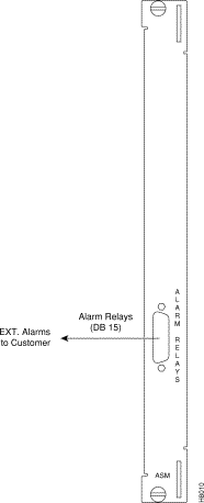
![]()
![]()
![]()
![]()
![]()
![]()
![]()
![]()
Posted: Fri Jan 19 16:46:02 PST 2001
All contents are Copyright © 1992--2001 Cisco Systems, Inc. All rights reserved.
Important Notices and Privacy Statement.