|
|

This chapter explains how to install the BPX.
 | Warning Installation should be performed by authorized personnel only. |
The BPX has the following site preparation requirements.
Before proceeding, go through this parts checklist to verify that all the parts you ordered are present, and that they are all in good condition. If there is anything missing or damaged, report it to your Cisco Order Administration representative.
Plug-in cards may be shipped installed or under separate cover. The exact number of cards will vary from site to site, depending on the selected configuration. The BPX is shipped with all unused slots covered by backplane inserts which prevent radio frequency emissions from the equipment. The unit must not be operated with any unused slots left uncovered.
Refer to the list below and check the number and type of cards shipped against the number and type of card you ordered.
| If a DC version, the correct number of Power Entry modules. |
| If an AC version, the unit has the correct number of power supplies (1 or 2). |
| For non- redundant configuration, one Broadband Controller Card. This can be either a BCC-3 or a BCC-32. |
| For a non-redundant configuration, one Broadband Controller backcard. For a BCC-3 front card, a BCC-3-bc backcard must be used. For a BCC-32 front card, a BCC-bc backcard must be used. |
| For a redundant configuration, two Broadband Controller Cards. These can be two BCC-3s or two BCC-32s. |
| For a redundant configuration, two Broadband Controller backcards. For BCC-3 front cards, these must be BCC-3-bc backcards. For BCC-32 front cards, these must be BCC-bc backcards. |
| One ASM card. |
| One LM-ASM card. |
| Correct number of BNI cards. |
| One line module backcard (e.g., BPX-T3-BC, BPX-E3-BC, MMF-2-BC, SMF-2-BC, or SMFLR-2-BC) for each BNI, as applicable. |
| Correct number of ASI-1 cards. |
| One line module backcard (e.g., BPX-T3-BC, BPX-E3-BC, MMF-2-BC, SMF-2-BC, or SMFLR-2-BC) for each ASI, as applicable. |
| One line module backcard (e.g., MMF-155-8, SMF-155-8, SMFLR-155-8, MMF-155-4, SMF-155-4, SMFLR-155-4, SMF-622-2, SMFLR-622-2, SMF-622, or SMFLR-622) for each BXM, as applicable. |
| All cables specified in the order. |
The following paragraphs contain safety information for system planners, installers, and maintenance personnel. The mechanical design of the BPX prevents any access to exposed voltages without the use of tools. When installed properly, all front and rear cards are held captive mechanically.
| Warning For protection against shock hazard, verify all power cords or cables are disconnected before servicing unit (there may be more than one). The highest voltage that may be present in the node when powered up is 264 VAC (AC systems) or 56 VDC (DC systems). |
1. In order for the BPX to function safely and correctly, along with peripheral equipment, use only the power cords, cables, and connectors specified for the attached peripheral equipment, and make sure they are in good condition.
2. Certain BPX nodes are supplied with two power feeds (cords). Before commencing installation or maintenance inside the cabinet, be sure both power feeds are disconnected from their respective sources.
3. Ensure that the BPX frame is attached to an isolated ground connection (connection attached directly to ground through an uninterrupted line).
4. A conduit hookup box is factory-installed on each DC Power Entry Module for sites requiring wiring to be enclosed in conduit. A plastic terminal block cover is also provided for installations that do not require conduit hookup. Install one or the other as protection for the DC input.
5. Before power-up, verify the node is powered from a dedicated AC branch circuit.
6. An insulated grounding conductor that is identical in size to the grounded and ungrounded branch circuit supply conductors, but is green with yellow stripes, is to be installed as part of the branch circuit that supplies the unit.
All apparatus (e.g., 48 VDC power supplies) connected to the BPX must comply with BS6301 or EN60950
Compliance with Emission requirements depends upon adherence to the installation steps in this manual, including installation of faceplates for all slots and the use of shielded cables between systems.
A fully loaded, AC-version, BPX node can weigh up to 213 pounds (97 Kgs). A fully-loaded DC-version BPX may weigh up to 163 pounds (74 Kgs).
 | Caution If the BPX is to be mounted in an enclosed cabinet, assure that a free flow of air in and out of the enclosure is provided. Contact Cisco Customer Service for further information. |
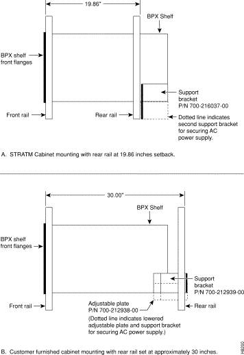
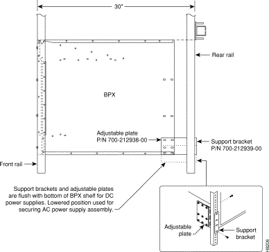
BPX shelves are designed to be mounted to two sets of vertical mounting rails in either a STRATM cabinet or a standard 19-inch equipment rack with unrestricted front to rear air flow. When installed in a STRATM cabinet (Figure 2-1), the front flanges of the BPX are secured to the front rails of the STRATM cabinet. In factory installations, rear support is provided by rear mounting rails in the cabinet at a setback of 19.86 inches. As an option, a rear set of rails located at a setback of approximately 30 inches may be used for rear support.
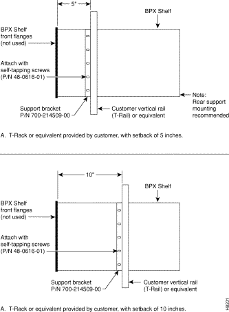
BPX shelves can also be mounted to an open T-Rail type rack (Figure 2-2) with unrestricted front to rear air flow. To facilitate this type of installation, brackets may be fastened to the BPX shelf at a 5 or 10 inch setback for supporting the front of the BPX shelf. Additional rear mounting support is also recommended. Contact Cisco Customer Service for further information.
For typical equipment configurations in a STRATM cabinet, refer to Appendix A.
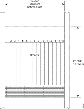
The BPX is designed for mounting in a standard 19-inch (48.25 cm.) equipment rack such as the standard STRATM cabinet. A minimum width between rails of 17.750 inches (44.45 cm) is required (Figure 2-3 and Figure 2-4). Mounting flanges are permanently attached to the front edge of the BPX shelf. It is recommended that the shelf be mounted with all plug-in cards temporarily removed to lessen the weight.
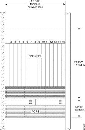
There are two types of BPX shelves, AC powered and DC powered. When an AC powered BPX shelf is installed, an AC Power Supply Assembly is installed directly below it. The DC Powered BPX Shelf contains DC power entry modules (PEMs) within the shelf itself and does not require an additional assembly for power.
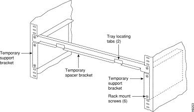
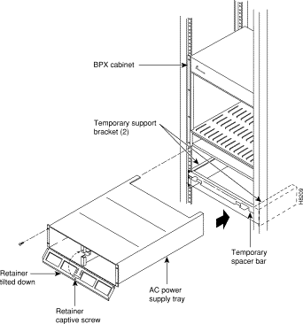
A temporary support bracket and spacer bracket is furnished to ease installation. The pallet tray part of the shipping container is used in the installation of the BPX. This wooden pallet tray that is shipped under the BPX chassis is used to lift, align, and support the chassis during installation in a rack.
The following instructions are for BPX Shelf installation in a STRATM cabinet.
To install the BPX in a rack proceed as follows:
Step 2 Remove the card retaining bracket from the front of the chassis by unscrewing the four Phillips screws. This bracket is used to retain the boards during shipping.
Step 3 Remove the Air Intake Grill and all front and rear cards from the shelf and temporarily set aside. Refer to "Installing Front Cards"section in this chapter for the proper procedure.
| Caution Ground yourself before handling BPX cards by placing a wrist strap on your wrist and clipping the strap lead to the cabinet. |
Step 4 Decide where the BPX is to be located. Refer to Figure 2-1 through Figure 2-4 for typical mounting dimensions. Also, for typical mounting configuration examples, refer to Appendix A. The appendix lists dimensions in inches, centimeters, and rack mouting units (RMUs). The top of the spacer bracket should be temporarily installed in the rack 22.75" (57.8 cm.) below the location selected for the top of the BPX chassis.
Step 5 Install the temporary support brackets and spacer bracket (shipped with the unit). Use two mounting screws to attach each temporary support bracket and two screws to attach the temporary spacer bracket to the rack (Figure 2-5 and Figure 2-6).
It is recommended that all BPX systems use a set of vertical support rails to provide additional support for the rear of the chassis. In the STRATM cabinet these are located at a 19.86 inch setback from the front in factory installations. Refer to the applicable installation sections in this chapter, "Installing a BPX Shelf, Rear-Rail Setback at 19.86 Inch" or "Installing a BPX Shelf, Rear Rail Setback at 30-Inch."
Step 6 If the BPX Shelf is being installed in a STRATM cabinet and is using factory installed rear rails located at a 19.86 inch setback from the front, go to the procedure in "Installing a BPX Shelf, Rear-Rail Setback at 19.86 Inch."
Step 7 If the BPX Shelf is being installed in a customer supplied cabinet using rear rail mounting support brackets located at a setback of approximately 30 inches from the front, go to the procedure in "Installing a BPX Shelf, Rear Rail Setback at 30-Inch."
The steps in this procedure apply to a BPX Shelf that is being installed in a STRATM cabinet and using factory installed rear rails located at 19.86 inches from the front. If the vertical rails are located at the rear of the cabinet (approximately a 30 inch setback from the front), use the procedures in "Installing a BPX Shelf, Rear Rail Setback at 30-Inch."
If the BPX shelf is DC-powered, the DC Power Entry Modules are factory-installed in the lower portion of the rear of the BPX shelf (Figure 2-7). Locate the DC Power Entry Module(s) and make sure it/they are equipped as ordered. If the BPX shelf is AC-powered, an AC Power Assembly will be installed below it.
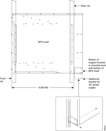
Figure 2-8 shows the location of the rear vertical rails (at a 19.86 inch setback from the front flange of the STRATM cabinet) and the corresponding support bracket location on the BPX shelf.
Proceed as follows to install either an AC or DC powered BPX shelf
Step 2 Secure one each support bracket to the back of the rear rail located at 19.86 inches from the front flange of the STRATM cabinet using #10-32 machine screws and flat washers.
| Warning An empty BPX enclosure weighs 75 pounds (34 Kgs.) and requires a 2 or 3-person lift to move into place. |
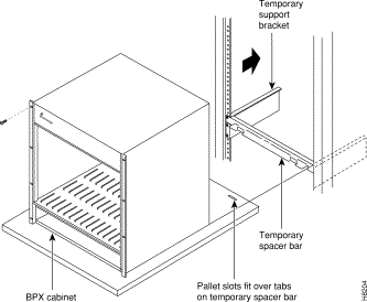
Step 3 With one person on each side of the BPX shelf, lift the pallet tray and BPX chassis positioning the slots at the rear of the pallet tray over the locating tabs on the spacer bracket (Figure 2-6).
Step 4 Slide the BPX shelf back over the temporary support brackets and into place.
Step 5 Attach the BPX shelf to the cabinet front rail using 8 each # 10-32 screws.
Step 6 Attach the BPX shelf to the previously installed support brackets by inserting 8 each #10-32 machine screws and flat washers from inside the back of the BPX shelf.
Step 7 Remove the temporary support brackets and spacer bracket.
Step 8 If this is a DC powered shelf, first proceed to "Making Power Connections" section, then proceed to "Installing the BPX Cards" section.
Step 9 If this is an AC powered shelf, first proceed to "Installing an AC Power Supply Tray" section, next to "Making Power Connections" section, then proceed to "Installing the BPX Cards" section.
The steps in this procedure apply to a BPX shelf that is being installed in a customer supplied cabinet with rear vertical rails located at a setback of approximately 30 inches from the front. If the vertical rails are located closer to the center of the cabinet (at a 19.86 inch setback from the front), use the procedures in "Installing a BPX Shelf, Rear-Rail Setback at 19.86 Inch" section in this chapter.
If the BPX shelf is DC-powered, the DC Power Entry Modules are factory-installed in the lower portion of the rear of the BPX shelf itself (Figure 2-7). Locate the DC Power Entry Module(s) and make sure it/they are equipped as ordered. If the BPX shelf is AC-powered, an AC Power Assembly will be installed below it.
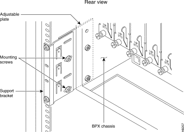
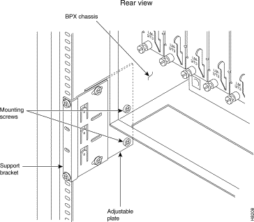
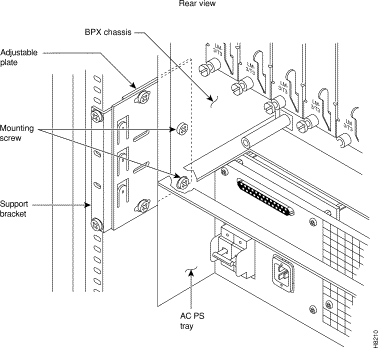
Figure 2-9 shows the location of the rear located third rails in a customer supplied cabinet and of the corresponding adjustable plates and support brackets on the BPX shelf.
Proceed as follows to install the BPX shelf. (Refer to Figure 2-9, and to either Figure 2-10, or Figure 2-11.):
Step 2 Slide the BPX shelf back over the support brackets and into place.
Step 3 Secure the BPX shelf to the front rail using 8 each #10-32 screws.
Step 4 Locate the two rear support brackets and adjustable plates in the miscellaneous parts kit.
Step 5 Position the adjustable plates with the tabs in the three punchouts facing up.
Step 6 Align the top and bottom holes in the adjustable plates with corresponding holes in the side panel of the BPX shelf. (The bottom of the plates should be approximately aligned with the bottom of a DC powered BPX shelf. They should be extended below the bottom of an AC powered BPX shelf so that the AC Power Supplies can be secured to the shelf.)
Step 7 Secure one each adjustable plate to each side of the BPX shelf using (2) each #10-32 machine screws and flat washers.
Step 8 Attach a rear support bracket to each one of the adjustable plates with 2 each 10-32 screws and washers. Do not tighten yet.
Step 9 Secure the support brackets to the rear located vertical rails using 2 each #10-32 screws. You may have to lift the BPX shelf slightly to align the holes in the bracket to the holes in the rack.
Step 10 Tighten the screws attaching the support bracket to the adjustable plate.
Step 11 Slide a cable strap over each of the three tabs on the support brackets.
Step 12 Remove the temporary support bracket and spacer bracket from the front of the cabinet.
Step 13 If this is a DC powered shelf, first proceed to "Making Power Connections" section, then proceed to "Installing the BPX Cards" section.
Step 14 If this is an AC powered shelf, first proceed to "Installing an AC Power Supply Tray" section, next to "Making Power Connections" section, then proceed to "Installing the BPX Cards" section.
All AC-powered systems are required to use a set of rear support brackets to provide additional support for the rear of the Power Supply Tray. To install the AC Power Supply Tray proceed as follows:
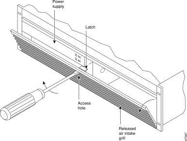
Step 2 Locate the small access hole in the top center of the front Air Intake Grille on the Power Supply Tray (Figure 2-13).
Step 3 Insert a slotted blade screwdriver (0.20/0.25 inch blade width) into the access hole until it stops (approximately 1 inch).
Step 4 Carefully rotate the screwdriver approximately a quarter turn in either direction. The top of the Air Intake Grille should spring out.
Step 5 Remove the Air Intake Grille.
Step 6 Slide the Power Supply Tray in the rack between the BPX shelf and the temporary support brackets and spacer bar (Figure 2-12). If cables are attached, use care to avoid damaging them.
Step 7 Install screws and washers to loosely secure power supply assembly to the front of the BPX shelf. Align the front flanges of the Power Supply Tray with the flanges on the BPX shelf and tighten screws. There should be approximately 1/16" clearance between the BPX shelf and the Power Supply Tray to provide sufficient clearance for inserting power supplies.
Step 8 Secure the rear support brackets to the Power Supply Tray using one #10-32 screw and flat washer on each side (Figure 2-14). Use the lower hole in the brackets.
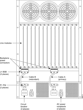
Step 9 Connect and secure a power supply interconnect cable (Cable A in Figure 2-15) between the primary AC Power Supply (_____plug end) and the BPX backplane power connector (_____ jack end).
Step 10 Connect and secure a second power supply interconnect cable (Cable B in Figure 2-15) between the redundant AC Power Supply and the BPX backplane power connector.
Step 11 Remove the temporary support bracket and spacer bracket from the front of the cabinet.
Step 12 Proceed to "Making Power Connections" section for AC power supply installation.
The AC Power Supply is an assembly consisting of an AC-DC Converter, cooling fan, LED bezel, and mounting frame. The AC Power Supply is installed and removed as an integral unit. There may be one or two AC Power Supplies depending on node configuration. They are housed in the Power Supply Tray.
Proceed as follows to remove and reinstall an AC Power Supply in the Power Supply Tray:
Step 2 Set the circuit breaker(s) at the rear of the Power Supply Tray to OFF.
Step 3 If not already removed, remove the Power Supply Tray front Air Intake Grille. Locate the small access hole in the top, center of the front Air Intake Grille for the Power Supply Tray (Figure 2-16).
Step 4 Insert a small slotted blade screwdriver (0.20/0.25 inch blade width) into the access hole until it stops, approximately 1 inch (2.5 cm).
Step 5 Carefully rotate the screwdriver approximately a quarter turn in either direction. The top of the Air Intake Grille should spring out.
Step 6 Loosen the captive screw in the center of the power supply retainer and rotate the hinged retainer frame down (Figure 2-16).
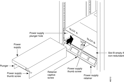
Step 7 Align the power supply in the PS-A slots at the bottom of the Power Supply Tray and gently slide it in part way (Figure 2-17).
Step 8 Continue to slide the power supply in until it mates with the rear connector.
Step 9 When the power supply is completely seated in its connector, the pin plunger on the left side of the supply will engage with a hole in the tray. If not, push firmly on the front edge until the power supply assembly seats in the connector.
Step 10 Screw the right-hand thumbscrew in finger tight.
Step 11 When a second power supply is provided, install it in the PS-B slot in the same manner after removing the Blank Panel from Slot B.
Step 12 Rotate the power supply retainer up and tighten the center captive screw.
Step 13 Install the Air Intake Grille. Press on the top center until the latch snaps into place.
Step 14 Proceed to "Making Power Connections" section, then proceed to "Installing the BPX Cards" section.
![]()
![]()
![]()
![]()
![]()
![]()
![]()
![]()
Posted: Fri Jan 19 17:08:21 PST 2001
All contents are Copyright © 1992--2001 Cisco Systems, Inc. All rights reserved.
Important Notices and Privacy Statement.