|
|

The BPX has two RS-232 serial data ports (labeled CONTROL port and AUXILIARY port) and an Ethernet port (labeled LAN) on the LM-BCC back card for attaching peripherals.
A network (or each domain in a structured network) must have at least one connection to a control terminal or StrataView Plus network management workstation. The StrataView Plus NMS workstation is used to configure and maintain all nodes in a network and report network statistical data. In addition, a network printer must be connected to the AUXILIARY port if you wish to print.
If it is desired to have Cisco Customer Service perform remote troubleshooting, a dial-in modem must be attached to the network. Procedures for attaching peripherals to the BPX are contained in the following paragraphs. Be sure to read the manufacturers literature to ensure that you have made the equipment ready for attachment, before attempting to attach it to the BPX.
Refer to the following documents for additional information on the following related subjects:
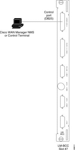
A basic VT-100 type terminal may be connected to this port for use in entering commands to bring up a new node. (Note: Since the StrataView Plus NMS workstation requires a LAN connection to a node in the network in order to perform its management functions, it is not connected to the Control Port during normal operation.) In these procedures, the term BCC is used to refer to either the BCC-3 or BCC-32 which are functionally identical, though each requires its own type of backcard, BCC-3-bc or BCC-bc (also known as BCC backcard), respectively.
Attach a terminal to the BPX as follows:
Step 2 For nodes with single BCC: Locate the CONTROL port connector on the LM-BCC in slot 7. Attach the RS-232/V.24 cable as shown in Figure 2-30. Go to Step 5.
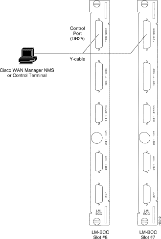
Step 3 For nodes with redundant BCCs: A Y-cable is required for this application. Connect one leg of the Y-cable to the CONTROL port connector on the backcard in slot 7 and the other leg to the slot 8 CONTROL port connector.
Step 4 Attach a RS-232/V.24 cable to the remaining leg of the Y-cable as shown in
Figure 2-31.
Step 5 Fasten the cable connector to the CONTROL port connector with the captive screws on the connector hood.
Step 6 Plug the control terminal (or StrataView Plus) power cord into the appropriate wall receptacle (115 VAC or 240 VAC) and switch it on.
Step 7 Set the port function for VT100/StrataView using the cnftermfunc command if connecting to a StrataView Plus workstation. If using a "dumb" terminal, select VT100 only (# 5).
Step 8 Make sure the CONTROL port and the terminal or workstation are set to the same baud rate and check the other communication parameters using the cnfterm command.
Refer to the following documents for additional information on the following related subjects:
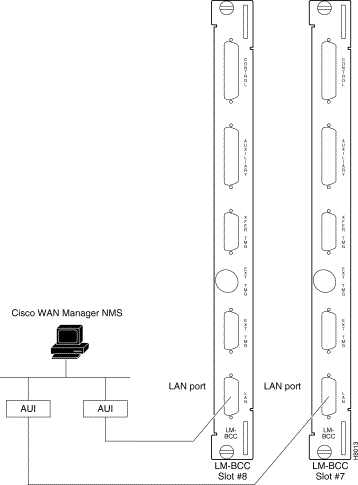
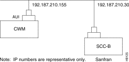
The StrataView Plus NMS is connected to an Ethernet port (LAN port) on a node in the network for the purpose of network management. The LAN port provides the capacity necessary for the network management traffic and network statistics collection. See Figure 2-32 illustrating this connection.
For access to the node using an Internet connection, the Internet Protocol (IP) address, IP subnet mask, TCP service port, and gateway IP address must be entered by the user with the cnflan command.
Step 2 Normally, the System Administrator will provide the IP addresses for the workstation and node. Refer to the SV+ Operations manual for instructions on configuring the SV+ workstation.
The addresses shown are just examples. Use the addresses obtained from your System Administrator. (This example is for a workstation named "hedgehog" at address 192.187.207.200. It also assumes that the BPX, IGX, or IPX node LAN port for node sanfran has been assigned an IP address of 192.187.210.30 and a hostname of sanfran. Your own host name and addresses will be different.)
192.187.207.200 hedgehog
192.187.210.30 sanfran
Step 3 Configure the LAN port on the BPX/IPX node using a dumb terminal or an RS-232 connection via the workstation (using the vt command, as applicable) to enter the appropriate cnflan parameters.
The cnflan command configures the node's communication parameters so that the node can communicate with a StrataView Plus terminal over an Ethernet LAN using the TCP/IP protocol. The parameters contain address information about the Ethernet TCP/IP network that is used to connect the StrataView Plus station to an IPX or BPX node. The values used must conform to those of the network and should be supplied by the Ethernet network administrator.
The cnflan command has the following parameters:
A cnflan screen is shown in Figure 2-33 for the LAN setup shown in Figure 2-34. An IP address of 192.187.210.30 has been entered as the active IP address for the node. The IP Subnet mask is entered as 255.255.255.0 for a Class C LAN network. The TCP service port is entered as 5120. Since the workstation and node are on different networks in this example, a gateway address of 192.187.207.1 (the address of the node serving as a gateway for SV+, in this example), which must be obtained from your System Administrator, has been entered. If the workstation and node are both on the same network, no gateway address is needed. The "Maximum LAN Transmit Unit" and "Ethernet Address" parameters are not configurable by the cnflan command. The "Ethernet Address" is a hardware address that is different for every node controller card, e.g., BCC.

Step 4 Connect the StrataView Plus workstation and the BPX node to a LAN network. The LAN port on the BPX node provides a DB-15 connector that can be connected to a Y-cable which in turn is connected to an AUI as shown in Figure 2-32.
Step 5 To test that a LAN connection to the BPX LAN port is okay, for example, for a hostname of "sanfran" entered in the config.sv file, you could enter the following at the SV+ workstation:
ping sanfran
Step 6 An IP Relay address needs to be configured for each node. Figure 2-35 shows an example of using the cnfnwip command to configure the IP Relay address for a node. Also, at the workstation, the /etc/hosts table and routing need to be set up for each node in the network. This is so that that network management using SNMP and statistics collection using TFTP via inband ILMI may be carried out. Also, assuming an isolated network for the nodes, the workstation must be isolated from the NIS reference pages in order that the SV+ workstation consults the /etc/hosts table. Refer to the StrataView Plus Installation and Operation manuals for further information.
Step 7 Once the workstation and BPX node interface have been set up, SV+ can be started. Figure 2-36 shows the dsplan screen after SV+ has been started and the communication sockets are active.

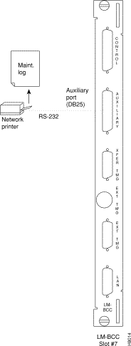
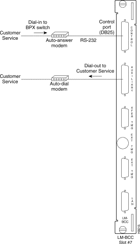
Figure 2-37 shows an example of a StrataView Plus workstation LAN connection to a BPX on a network with no gateway router, nor connection to another LAN. This type of LAN connection could also be connected through a "Hub" which is essentially a signal splitter (passive or active).
In most systems, the network printer will be connected to a serial port on the StrataView Plus NMS terminal server. The maintenance log and all statistics data will reside on the StrataView Plus. However, it is possible to connect a printer to a node and use various BPX system software print commands to print locally. This may be helpful during the initial network installation phase.
Appendix B, in the BPX Reference Manual, lists the types of printers supported by the BPX along with configuration settings. Appendix C, in the BPX Reference Manual, lists the pin assignments for the AUXILIARY port on the BPX. Attach the printer to the BPX as follows:
Step 2 For nodes with single BCC: Connect the RS-232/V.24 printer cable to the AUXILIARY port on the LM-BCC back card (Figure 2-38). Go to Step 5.
Step 3 For nodes with redundant BCCs: A Y-cable is required for this application. Connect one leg of the Y-cable to the AUXILIARY port connector on the LM-BCC in slot 7 and the other leg to the AUXILIARY port connector on the LM-BCC in slot 8.
Step 4 Plug the printer power cord into the appropriate AC outlet (115 VAC or 240 VAC).
Step 5 Set the port function for printer using the cnftermfunc command.
Step 6 Make sure the control port and the printer are set to the same baud rate and check the other communication parameters using the cnfterm command.

A modem may be connected to each BPX node to provide remote access by Cisco Customer Service (Figure 2-39).

These modems connect to a standard telephone line wall jack. The modem connections require special cables and setup procedures. Refer to the "Peripherals Specifications" appendix in the BPX Reference Manual, for instructions on connecting and setting up the modems. If the BPX is equipped with redundant BCCs, an RS-232 Y-cable must be used for these connections.
The BPX provides connections for supplying a timing signal to synchronize the operation of an adjacent IPX node. A connector on the BPX LM-BCC back card, labeled EXT CLK OUT supplies a clock signal at either a T1 or E1 rate which can be connected to the IPX EXTERNAL CLOCKS connector on the IPX SCC back card (Figure 2-40). This uses a straight-through DB15 to DB15 cable, male to male. See Appendix C, in the BPX Reference Manual, for pin-outs.
If the BPX node is to be synchronized to some other external equipment or a local digital central office, one of two other connectors on the LM-BCC can be used to provide a clock input. A DB15 connector labeled EXT CLK IN can be used to connect a balanced T1 or E1 signal, synchronized from some higher-level source, to the BPX. If an unbalanced 75-ohm E1 signal is available as the timing source, a BNC EXT CLK IN connector is also provided. The BPX senses an active signal at any of these inputs and automatically synchronizes to this source rather than the internal Stratum 3 clock source.

Before operating the BPX, check that the following procedures have been performed:
Step 2 The BPX power cord is plugged into an appropriate power outlet.
Step 3 The full complement of cards for the specific node are mounted in the correct slots, correctly seated, and locked in place.
Step 4 The T3 or E3 connections are attached to the appropriate LM-3T3/3E3 faceplate.
Step 5 A control terminal (or StrataView Plus Work Station) is connected to the CONTROL port on the LM-BCC in back slot 7/8, and the terminal's power cord plugged into the appropriate voltage wall outlet.
Step 6 If needed, a printer may be connected to the AUXILIARY port on the LM-BCC in back slot 7/8 and the printer power cord plugged into the appropriate power outlet.
Step 7 If needed, a modem(s) may be connected to the CONTROL port or AUXILIARY port, as applicable, on the LM-BCC in back slot 7/8, and the modem(s) power cord(s) plugged into the appropriate power wall outlet.
Step 8 From the back of the BPX cabinet, turn the power switches to the ON position.
Step 9 From the front of the BPX, observe the cards go through initial diagnostic self-tests.
The BPX software provides a group of diagnostic tests to be run on the system's hardware at power-up. The startup diagnostic either passes or fails the BCC(s) tests. The test result is displayed on the control terminal screen as pass or fail. Figure 2-41 illustrates a successful power-up diagnostics sequence.
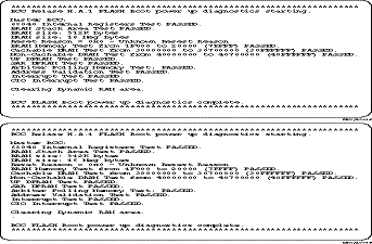
If a BCC fails the power-up diagnostic, it will not boot. When that happens, do the following:
Step 2 Reseat the BCC in the same slot.
Step 3 Wait for the power-up diagnostic to run.
Step 4 If the BCC fails the power-up diagnostics a second time, replace it with another BCC that is known to have passed the test.
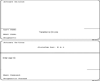
Once the software has successfully booted up, the NMS terminal will display the software on-line screen (Figure 2-42). At this point, you may login as a user to the node.
![]()
![]()
![]()
![]()
![]()
![]()
![]()
![]()
Posted: Fri Jan 19 16:48:46 PST 2001
All contents are Copyright © 1992--2001 Cisco Systems, Inc. All rights reserved.
Important Notices and Privacy Statement.