|
|

This chapter describes how to set up FastPAD network maps. Once a set of maps, consisting of parent and child-submaps, is set up, you can perform management functions with APS. Management functions are described in the chapter "Management Operations."
Follow the steps below to set up the FastPAD network map:
Step 2 For the parent map, select the FastPAD Network icon from the HPOV Add Objects Network palette to represent multiple nodes.
Step 3 Connect regions (Network icons) with the Add Connections dialog, under Edit.
Step 4 Double click on the Network icon to create the child submap.
Step 5 Add each node for region with the Add Objects Netdevice palette.
Step 6 Enter Node Name and X.25 Address in the View/Modify Objects Attributes dialog.
Step 7 Enter Node Name in the Describe/Modify Symbol dialog.
Step 8 Add connections between nodes with the Add Connections dialog, under Edit.
Node parameters (Step 6) include X.25 address and Node name, as well as Polling Type and Polling interval. Once these parameters are set, APS automatically polls each node for management information.
When started, the first screen to appear is the Root window, displaying the IP Map. (See Figure 4-1.)
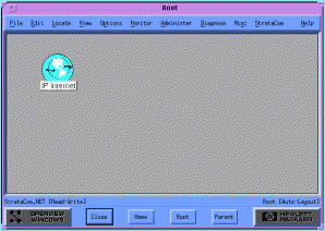
From the Root Map Edit function, select Add Object. The Add Object Palette is displayed. (See Figure 4-2.)
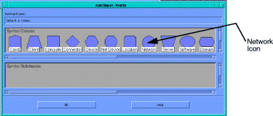
Click on the Network Icon, and you will receive additional selections in the Add Objects Palette. (See Figure 4-3.)
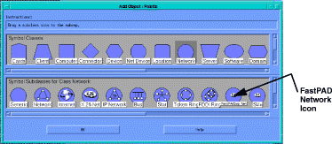
With the center mouse button, click on the FastPAD Network Icon, and drag it to the Root Map.
When you release the mouse button, placing the FastPAD Network Icon in the Root Map, you receive the Add Object Dialog Box. (See Figure 4-4.)
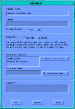
This dialog box permits an object to be added to the Map. At a minimum, you must enter a Name Label for the object. If no Name is entered, the icon is removed from the map.
For a name to appear underneath the icon, place the mouse pointer over the icon and click the right mouse button. Select either Describe/Modify symbol, or Display Label and enter the same name entered in the Add Object dialog.
Once added, the Network, with Name, appears in the Root Map. (See Figure 4-5.)
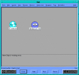
This will be the Parent Map to which greater detail is added in one or more Child Submaps. Multiple layers of Maps prevent one map from becoming too complicated to effectively work with.
Removing Node or Network icons from a map can be done in two ways:
1. Highlight the icon and select Edit ->Delete->From All Submaps
2. Place mouse pointer over icon and click right button to invoke pop-up menu and select Delete Symbol
For this example, assume there are:
In the example below, a Child Submap under the Root Map above is created.
To create a Child Submap underneath this Map, double-click on the FastPAD Network Icon. You will receive an OpenView Question Dialog (Figure 4-6):

Default is suitable for this submap. Select Modify if you wish to modify settings as described in the HP OpenView User's Manual.
Once selected, you receive the Submap parameters Dialog. (See Figure 4-7.)
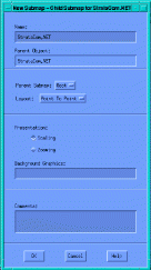
This dialog indicates that the submap is located under Root. Again, at a minimum, you must enter a name.
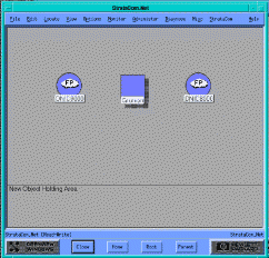
Below, two Network icons for two regions (DNIC8000 and DNIC9000) and a generic icon (labelled GRUNION) to indicate the IPX network through which the FastPAD regions are connected have been selected from the Add Objects palette and placed on the Child submap.
Another submap will then be created for both DNIC8000 and DNIC9000 regions. (See Figure 4-8.)
Next, connect objects. Select Add Connection under Edit. You receive the Add Connections dialog: (See Figure 4-9.)
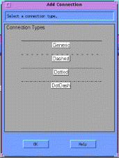
Select a type of connection to be illustrated. The type of connection illustrated is not significant. In the example below, two connections have been added: DNIC8000-to-GRUNUION, and DNIC9000-to-GRUNION.
With the Add Connections dialog window still open, click on the source object, followed by the destination object, and they are linked on the screen. See Figure 4-10.)
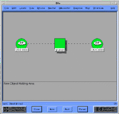
When a connection is made, the Add Objects dialog appears for the connection. You may add any information desired; only a name is required.
Similar to above, objects will be added, however, this time they will be Network components.
Click on Add Object under Edit. (See Figure 4-11.)
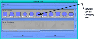
This time, select the Network Device category. You receive the Add Object Palette with a selection of Network devices. (See Figure 4-12.)
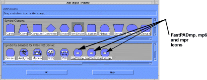
Using the Center mouse button, drag network device icons to the map.
The map below illustrates multiple network nodes, and a "Computer" icon (Audey) from the primary object palette to represent the APS workstation, as well as the primary (parent) level object GRUNION (IPX Network) through which the child submap (DNIC8000) is connected the other regional network. (See Figure 4-13.)
As described above, for each icon in the example below:
1. Name has been entered for both Symbol and Object.
2. Connections have been made between icons.
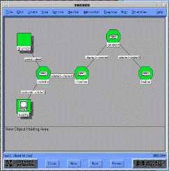
For a name to appear underneath the icon, place the mouse pointer over the icon and click the right mouse button. Select Describe/Modify symbol, and enter the same name entered in the Add Object dialog. This is for display purposes only; to access the node through the X.25 connection, the Name must also be entered in the Object Description dialog.
Place the mouse over the icon, and click the right mouse button. Select Describe/Modify Object, and you receive the Object Description dialog. (See Figure 4-14.)
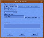
Click on Access Product Supervisor at the top, and then select View/Modify Object Attributes and you receive the Attributes for Object dialog. (See Figure 4-15.)
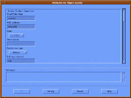
Any mix of alphanumeric is accepted. Node name appears on map underneath the node icon.
The correct X.25 address for the node must be entered, consisting of DNIC, Zone, and Subscriber = 99. For example, 90022099. 99 is the subscriber address for the supervisory process of the FastPAD node.
Model is automatically set to one of the following: FastPADmp, FastPADmp6, or FastPADmpr.
This is an information-only field.
Can be set to active, passive, or not monitored. Active nodes are monitored as described in the chapter "Management Operations."
Polling Interval is the time, in minutes, between polls of the node. APS places an X25 call and collects information on events, alarms, and monitor information for each poll. The default value is 10 minutes.
This display shows the last day and time that the node was polled by APS. Each time the APS polls a node, this field is updated.
These are information-only fields and cannot be edited; they indicate the FastPAD operating software level and are updated any time new information is discovered upon polling.
These are information only fields and cannot be edited; they are updated whenever one of these functions is performed.
This is the address to be used if the primary X.25 address fails, and X.25 Backup Address Used (see below) is set to True.
True or False is selected by radio button; if set to True, X.25 Backup Address will be tried if the primary X.25 address fails.
This parameter defines the CUG (Closed User Group) to be used if the X.25 line is configured to use it, and "CUG Used" (see below) is set to True.
True or False is selected by radio button; if set to True, CUG defined above will be used if the X.25 line is configured to use it.
This is the CUG to be used if the primary CUG fails, and Backup CUG Used (see below) is set to True.
True or False is selected by radio button; if set to True, Backup CUG defined above will be used if the primary CUG fails.
True or False selects whether or not Backup Alarm is used.
![]()
![]()
![]()
![]()
![]()
![]()
![]()
![]()
Posted: Thu Jan 25 14:25:52 PST 2001
All contents are Copyright © 1992--2001 Cisco Systems, Inc. All rights reserved.
Important Notices and Privacy Statement.