|
|

For each terminal connected to a line of the FastPAD there are, whatever protocol is used, two groups of parameters to configure:
Group 1: | Parameters defining the choice and the decision to use a protocol "p" on a certain line (to configure on C1R1P0 to 35). |
| For each user line the additional parameters allow to configure the functional options offered. |
Group 2: | Parameters defining the X.25 Interface of the user line facing the X.25 node, represented by the internal switch of the FastPAD. This switch manages the virtual circuit between the network line and the user line. |
| These are the network parameters of level (OSI) 3 of the X.25 recommendation. |
With this organization, all network services can be offered to each line, independent of their protocol.
These parameters define the operation mode of the following levels:
These parameters define the level 3 interface facing the internal switch. The following parameters are distinguished:
Example: CUG, throughput class, reversed charging...
Example: Packet length, window size...
They are put together for all protocols in Cl2Rx and the following classes, as a function of the protocol.
X.25 | C12 | X.25 parameters |
Asynchronous | C7 | Abbreviated calling table |
| C8 | Automatic calling table |
| C13 | Parameter X.3 |
X.25 PVC | C17 | PVC table |
| C8 | Automatic calling table |
X.25 PSTN | C13 | Extension parameters |
| C20 | Modem initialization table |
| C21 | XID frame table |
| C22 | X.25/PSTN conversion table |
SDLC | C8 | Automatic calling table |
| C19 | Clusters |
VIP | C8 | Automatic calling table |
| C13 | Station address |
| C19 | Controllers |
BSC 2780/3780 | C8 | Automatic calling table |
| C13 | Station address |
| C19 | Terminal description |
BSC 3270 | C8 | Automatic calling table |
| C13 | Station Address |
| C19 | Controller description |
HDLC and Frame-Relay | C8 | Automatic calling table |
Frame-Relay (subscriber) (FRA)/FRCE | C17 | DLCI table |
Frame-Relay/FRTE,FRSE | C32 | Frame relay PLL couple |
Transit type | C30 | Dynamic X.25 parameters on network FR or B or D channels. |
Network (FRTE) | C30 | Dynamic X.25 parameters on network FR or B or D channels. |
D channel (ISDN) | C22 | X.121-PSTN/ISDN conversion table |
B channels (ISDN) | C30 | Dynamic X.25 parameters on network FR or B or D channels. |
PLL in D channel (ISDN) | C13 | PLL/TEI/profile number relations (defined In C30). |
| C30 | Dynamic X.25 parameters on network FR or B or D channels. |
| C22 | X.121-PSTN/ISDN conversion table. |
MLP | C25 | Bundle of MLP lines. |
Connection | C17 | SLL table |
| C8 | Automatic calling table |
| C31 | Permanent stations and Ethernet filtering |
Virtual IP router | C24 | Parameters of IP router connection |
Connection | C17 | SLL table |
| C8 | Automatic calling table |
SNMP, IP Routing | C31 | Ethernet filtering and IP router |
They are put together in C12Rx for each protocol and in C18 when a CUG has been allocated to the X.25 call. See Appendix A of this manual.
To facilitate the operations, the operator has a number of profiles available. A profile is a predefined set of parameters of the groups 1 and 2.
The address fields, present in the call packet. are used to identify the two communicating parties. They are connected to each other when the X.25 virtual circuit is established.
The presence of the fields depends on the type of line. It is configured in C12RxP45:
When one address has been selected the type of address changes with the origin of the call:
The FastPAD address format is derived from the network address and it is structured in three hierarchical levels (see "General routing principle" of this chapter).
To adapt the external subscriber format to the internal network format, there is an internal address conversion mechanism; it is available for each line (subscriber and network).
Two tables are available. These tables are configurable for each line and they can be accessed via C9R11 and C9R12.
This conversion takes place according to the value of parameter C12RxP89.
There is an additional feature introduced when the address to convert is not configured in the tables; the call will be refused or the call will be returned in its original format. The choice of the behavior depends on the parameter C12RxP89.
Table C9R11P0 to P199 adapts the external address to the internal address.
The different possibilities are:
Table C9R12P0 to P199 adapts the internal addressing to the external addressing pLAN.
The different possibilities are here also:
1. Description
2. "Aimed Point" Address
3. Configuration of "Aimed Point"
| · C12R3P89 |
| = | 64 |
|
|
|
|
| Calculation of aimed point. | |
| · C9R11 | PY | = | 567AAAAAA | Initial address + absorption |
|
| Py + 1 |
| 9000 | Calculated address of aimed point |
| · C9RO | Px | = | 9000 | Known DNIC |
| · C9R1 | Px | = | 1, 1, 0, 2 | Routing on 1 line, 1 line, fixed 0 to line 2. |

4. Constraints and Limits
The purpose of this service is to enable a private network composed of several subassemblies, and knowing only the addresses belonging to its own numbering pLAN, to access a remote subassembly via the "Transpac" network. What is involved is the provision of an end-to-end service between users of a private network via "Transpac." In a transparent manner for the users (in particular as concerns their numbering pLAN).
A configuration parameter, by line, allows the backup at the input of the switch (or the reproduction at the output of the switch) of the following parameters in an address extension facility:
A second configuration parameter, by line, allows the determination of the behavior to be adopted on the X.25 fields at the input of the switch.
The processing resulting there from may include:
and the possible actions may be:
In practice, to allow access to the intelligent network of Transpac, the functional steps are:
The addresses of the calling party, the called party (and possibly the CUG and RC) are reproduced on any subscriber output line to the private network management.

Addresses a and b are in the private network addressing plan.
Addresses A, B, X, Y are the addresses of the ports.
(0) - | The call-request packet sent on the "private network management" subscriber line has the following form: | |
| @ calling: a | @ called: b |
During the processing of the incoming call, the addresses are modified after backup in the address extension facility
| @ calling: A | @called: | @IR | (Intelligent Network Server address) |
| CUG and RC according to the configuration. | |||
(1) - | The call transmitted to Transpac is the following: | |||
| @ calling: A | @called: | @IR |
|
Address extension:
| @ calling: a | @ called: b |
CUG and RC according to the configuration
(2) - | The call transmittal by Transpac is the following: | |
| @ calling: XA | @ called: B |
Address extension:
| @ calling: XA | @ called: B |
| CUG and RC according to the configuration | |
(3) - | On the "private network management' subscriber line there is a reproduction of the addresses, of the CUG and the RC (according to configuration) | |
| @ calling: a | @ called: b |
Private network management configuration:
By line, two connection parameters are defined:
The values used are:
By default, this parameter is equal to 0 (no processing).
Parameter 111 consequently makes it possible, at the input of the switch, to back up in the "address extension" DTE facility the addresses and even the CUG and RC. This backup takes place before any actions that may be requested by the parameter 112. At the output, this same parameter allows the reproduction of these data from the address extension facility.
Parameter 112 defines the behavior to be adopted. This behavior corresponds to a row in class 26. Class 26 "Table of X.25 field modifications" has only one recurrence and 20 parameters (each parameter has 24 bytes). This parameter is valid only if parameter 111 is different from 0 and is analyzed only on an incoming call.
By default, parameter 112 is equal to 0, which means; no X.25 field to be modified. Value 1 points to parameter 0 in C26 (value 2 to parameter 1 in C26, etc.).
The actions in C26 have the following format:
Type_action, X.25 field, <value> <value>:optional | ||
Type_action: | A | Reserved (e.g. Addition at input of FastPAD) |
| B | Addition at output of FastPAD |
| C | Change |
| D | Destroy |
| F | Forbid |
X.25 field: | E | called party address |
| A | calling party address |
| F | Facility |
| B, C, D | reserved |
Only the following combinations are managed:
Line 1 of equipment 900240 is a subscriber line with private network addressing. It is configured as 1 address. and subscribes to called party and calling party address transport. The addresses of the outgoing call-request packet from the FastPAD must be modified to furnish:
Moreover, the addition of the facility F70100 is desired at the output of FastPAD.
The configuration is then as follows:
| Pl11 = | 3 private network management (transport @ calling party and @ called party) |
| Pl12 = | 1 behavior in C26 |
| PO:DACE90402180BFF701000
|
|
This service allows the checking of the address furnished by the DTE (caller's address at the request of the called party; its called party address upon call confirmation or clearing request) and enables the DTE to use signalling packets having both caller and called party addresses.
For a two-address DTE, the service allows the checking of the caller's address (respectively the called party's address furnished by the DTE during the accepted call or clearing request). If the addresses are not identical, the call is cleared. Otherwise, the call continues normally. The check is carried out in relation to the secondary address if it is configured; otherwise in relation to the main address.
For a single-address DTE, the secondary address (or the main address if the secondary address is not configured) of the DTE is inserted. If the length of the sub-address plus the address to be inserted is more than 15 digits, the call is cleared. This processing replaces the usual address completion processing.
For a non X.25 DTE, the address to DNICZOAB format generated by the FastPAD is replaced by the secondary (or main) address.
For a two-address DTE, the main address received is replaced by the secondary address of the DTE (if the latter is configured).
If the length of the secondary address plus the SA is more than 15 digits, the final address is truncated.
For a single-address DTE, the address furnished is eliminated to leave only the SA.
Call party address
In two-address mode:
In single address mode:
In single-address mode.
If the calling address if furnished, the call is freed.
In two-address mode:
In single-address mode:
This service is implemented from a connection parameter allowing its activation. This parameter is defined in C12P89. Parameter 89 is already used for address conversions and the Aimed Point. Bit 7 remains available. By default, this bit is equal to 0 and the service is thus not activated. This bit, called "DTE" address presence authorized" is coded as follows: bit 7: DTE address check/insertion (1/0: yes/no).
To check or be able to insert the address furnished by the DTE, C9R11 is used (conversion of address on incoming call). This table can contain 100 addresses. For the same DNICZOAB, a main address and secondary address may exist. In order to identify a secondary address, it is marked with an "E" at the end of the DNICZOAB referring to the secondary address.
The order in which the main and secondary addresses are filled in on the same line in C9R11 is not subject to any constraint. However, it is recommended that the main address be configured first and then the secondary address in order to minimize the travel time of the table during a call from the remote network (in fact, the main address which allows the routing through the use of Aimed Point).
This conversion makes it possible:
Reminder:
Profile 564 is used at the remote network FastPAD interface. This profile differs from profile 0 on four parameters:
This functionality is used to present an address other than the main address to any party as a calling address. This address, called the Secondary address, is the one appearing on the invoice.
This service does not use any configuration parameter through DTE access.
When a secondary address is present on a DTE access, this address is stored in C9R11, the letter E being marked at the end of the corresponding DNICZOAB. When the main and secondary addresses are configured. the main address is first filled in on C9R11 (to allow routing) and then the secondary address.
Mode 1: address with Ctrl/insertion parameter = yes
The secondary address S is inserted as calling address if it is present. Otherwise, it is the main address P which is inserted.
Mode 2: addresses with Ctrl/insertion parameter = yes
When the secondary address is filled in, the checking of the caller's address furnished by the DTE covers this secondary address. If the secondary address is not configured, the check is carried out with the main address.
Mode 1: address with Ctr/insertion parameter = yes
The main address is removed from the called address.
Mode 2: addresses with Ctr/insertion parameter = yes
The call transits in the network with its main address to allow routing. If the secondary address is provided for, the call is presented to the DTE with its secondary address (or else with its main address).
It is the secondary address it is provided for (or else the main address) which is inserted by the network (or by the DTE when it is authorized to furnish its address) in the called party address field of a communication packet accepted or on a clearing request in association with the CLAMN service.
The routing available in the FastPAD network is a decentralized service and thus managed in each switching node (subscribers node and transit node).
The routing service is activated systematically in each switch. It analyzes the called address of the incoming call packet.
The next step is, by means of decision tables, to deduce the configured routing and the outgoing line number enabling the called party to be reached.
The routing service uses a fixed internal addressing pLAN which allows the consultation of routing tables. To allow the adaptation of addressing to the DNIC ZO AB format used by the routing service, a certain number of mechanisms may be put in place:
Consecutively, the routing algorithm is executed as follows:
1. Conversion of the called address (if necessary),
2. or aimed point, or intelligent network access, hierarchical analysis of the called address field according to three levels as mentioned in Chapter 4 (configuration).
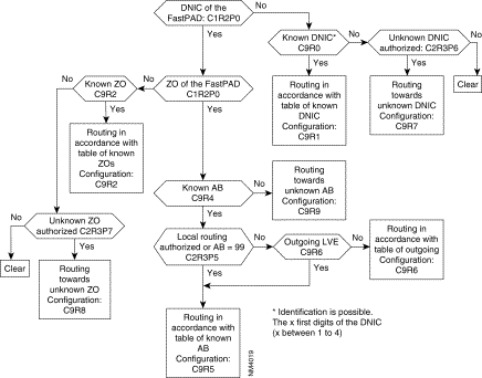
Example: Subscriber A, identified by its address 9000 10 01, establishes a virtual circuit with subscriber B with network address 9000 20 02. The following takes place:
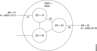
1. Routing activated in the node with ZO = 10:
2. Routing activated in the node with ZO = 20:
During implementation of a new network, the system can take into account additions and withdrawals of subscribers and nodes, without constantly changing the routing tables.
There is another feature available when the called address is not configured in the tables.
There are two configuration possibilities:
This deterministic routing is then reported in the adjacent network element (other switch, terminal).
When it is not possible for the routing to deliver a call the following will happen:
Upon reception of a call-request packet, final choice of routing within a FastPAD network may be entrusted to the Dynamic Adaptive Routing (DAR) function. This service allows automatic routing of calls according to the shortest path valid at the time of the call. To accomplish this, knowledge of the network topology is acquired and then updated automatically by an internal self-learning mechanism. The use of this service consequently no longer requires manual configuration of the routing tables to the extent that the DAR function manages its tables dynamically and in real time.
The routing protocol used is of the decentralized type with local calculation of routes. It is distributed on each FastPAD switch of the network.
In a network, all the FastPAD switches equipped with the DAR service constitute a routing domain within which transit calls are routed automatically. To manage the calls intended for a subscriber outside of the domain of DAR, two possibilities are offered:
REMARKS: The Dynamic Adaptive Routing service is not a substitute for the Adaptive Routing Service presented in the preceding paragraph. It is compatible with it and constitutes an additional routing service. In particular, the routes chosen dynamically by the DAR are subject to anti-loopback control.
Each switch of the DAR domain is capable of identifying its neighborhood (i.e. for each inter-node line, the identity of the neighboring switch) and then distributing this Information throughout the domain. The information packet distributed is called LSPDU (Link State Protocol Data Unit). To accomplish this, the DAR function of each node establishes a permanent VC with all the adjacent nodes which are equipped with the DAR function. The established VC makes it possible to exchange recognition packets between DARs (HELLO protocol) and then to distribute the topology information. This distribution mechanism is activated periodically (configurable parameter). It is also triggered exceptionally following a change in the network topology (putting in or out of service of a line of a domain node). The information thus gathered by each switch is stored in an internal data base and used for the calculation of routes. This calculation is performed periodically or exceptionally and makes it possible to obtain, for each node of the domain, the best route in terms of number of nodes crossed (number of hops). These routes are used for the selection of routing.
Dynamic Adaptive Routing is called in a manner similar to routing on a line. In the routing table corresponding to the desired routing, it is necessary to configure the DAR function number which is 48. For example, in class 9 recurrence xx. the configuration of routing may be:
If, for example, the type of routing consists in taking the list of the lines in a preferential order, the call will be routed preferentially on line DL1 and then, if the call is unsuccessful, the choice of the line will be entrusted to the DAR function.
Finally, if the DAR is unable to reach the party (absence of known route), the call is transmitted over line DL2. The different examples which follow describe some applications of the DAR.
Examples:
1. Automatic intra-domain routing

2. Automatic "backup" routing
The automatic routing service of the DAR may be configured as a backup line. In a FastPAD network in which all routes have been configured manually (tables C9R0 to C9R4), the DAR service may be called upon in the event of failure on the configured routes (for example, 2, 2, 0, DLi, 48 in C9R1). If the failure is due to line or switch trouble, the DAR knows how to find the best route available to reach the subscriber or the node desired.
REMARKS: In order for any new switch introduced into the domain to be immediately reachable, it is preferable to maintain preferential routing on DAR for calls intended for unknown DNICZO addresses.
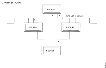
In the following figure, when a subscriber of node 900010 transmits a call intended for a subscriber of 900040, the call-request packet is routed onto node 900020 (fixed routing configured). With line 3 out of service, node 900020 entrusts the routing to the DAR function. The call is then routed according to the shortest path valid towards node 900040, i.e. line 2 towards node 900030.
Configuration of routing on DNICZO = 900040:
900010: C9R1 = 2, 2, 0, 1, 48
900020: C9R1 = 2, 2, 0, 3, 48
900030: C9R1 = 2, 2, 0, 4, 48
3. Dar and aimed point
 DAR and Aimed Point
REMARKS 1: In the X.25 connection profiles (profiles 4 and 5), the default values of the parameters previously described are compatible with DAR operation; only parameter 124 must be set so that the line is managed by the DAR.
REMARKS 2: V10.1 - V10.2 compatibility
For a V10.2 software version of the DAR function running on equipment in V10.1 configuration, it is necessary to add DAR subscribers (real path and user interface) in the table of internal subscribers (see C4 of configuration manual).
The parameters enabling the checking of the operation of the DAR function are in class 24 recurrence 5. The default values of these parameters are configured in profile 110. Some of them are capable of being modified according to the operating mode of the DAR desired.
Three DAR operating modes may be configured:
This parameter is used to set the distribution period for topology information (LSPDU) exchanged between DARs (values between 1 and 250 in steps of l 0 seconds; default value = 3). If this period is set at a high value, a node which is starting requires a long time to completely update its data base. This node is however known to the rest of the domain (owing to the "exception" distribution mechanism) but it knows only its immediate neighbors before the distribution of all the LSPDUs of the domain.
This parameter is used to set the maximum number of information packets (LSPDU) that a DAR can store in its data base. In order for all the DAR switches of a routing domain to be taken into account, the value of this parameter must be at least equal to the number of switches in the domain (values between 1 and 250; default value = 50). e.g.: for versions V10.2 and V11.1, the size of the network is about 50 nodes; beyond this number, the computation time may become very long.
This parameter is used to set the calculation period for routes with the shortest path used by the DAR. In order for the calculation of these routes to be carried out with the latest topology information (LSPDU) coming from all the DAR switches of the domain, it is preferable that the calculation period be at least twice as long as the LSPDU distribution period (values between 1 and 250 in steps of 10 seconds; default value = 6).
This parameter is used to set a threshold associated with the life of the LSPDU, below which the DAR sending the LSPDU is requested to redistribute a new LSPDU In the domain. This mechanism avoids the clearing of LSPDUs which are transmitted at low frequencies (values between 1 and 250 in steps of 10 seconds; default value = 6).
This parameter is used to lock, for a period of time, the calculation of routes which is initiated following the reception of an exception LSPDU (i.e. following a modification in the topology of the domain). This mechanism spares the DAR the task of performing several times the new route calculation to the extent that several exception LSPDUs will be distributed following the topology change: all the neighbors of the node concerned will transmit an exception LSPDU (values between 1 and 250 in steps of 10 secondS; default value = 2).
When there is a transfer via the ISDN, the routing knows only about the SO interface and not about the B-channels. The line number is the D-channel.
The line number is determined by the connect function: channel B1 or B2 or the PLL number.
The network processor manages the three interface levels (layers) between synchronous equipment and the public network.
The levels/layers are defined in the ITU-T X.25 recommendations and in the OSI (Open System Interconnection) standard, issued by the ISO (International Standardization Organization).
These three levels/layers, managed by the FastPAD equipment, are:
| Levels | Layers according to the ISO standard | Levels according to the ITU-T recommendations |
|---|---|---|
1 | Physical | Physical |
2 | Data-Link | Frame |
2 | Multi-Link | Multi-Link |
3 | Network | Packet |
This level transmits series of bits over the physical interconnection medium.
This level is responsible for the error-free routing of data blocks over the physical line.
The operating principle of the frame level is in conformity with the LAP-B (Link Access Procedure-BaLANced) module 8 and 128 procedure defined in the ITU-T. This procedure is equivalent to the "baLANced" mode of the HDLC standard issued by the ISO.
On this level, the network processor might be configured in the following modes:
The frame level is established when the DTE-configured equipment sends an SABM frame and the DCE-configured equipment replies with a UA frame (SABM = Set Asynchronous Response Mode; UA = Unnumbered Acknowledge).
The FastPAD equipment takes the initiative to
The local as well as the remote party of the FastPAD equipment could take the initiative to connect or disconnect the frame level (as is the case in the DTE mode) by sending SABM or DISC.
The FastPAD equipment does not take the initiative to connect or disconnect the frame level. It issues a DM (= Disconnect mode) to indicate that it requests a mode setting command. The response could be:
Whatever the type of connection (DTE, DCE or DSE), the FastPAD equipment manages contention e.g. in case two SABM frames are sent, one by the DTE and one by the DCE equipment.
The multi-link procedure is defined in ITU-T norm X.25-84. Its function is to distribute the packets among the available lines, each line operating according to the single line procedure, and restore the sequence of the packets on the remote side for further transfer to the packet layer.
To enable an MLP line to be managed, the line must be configured as belonging to an MLP bundle of the processor of the FastPAD network. Configuration of the MLP bundle takes place in class 25, recurrences 0 to 8.
The lines that may be configured in a bundle are of the dedicated or switched type (PSTN or ISDN). A switched line may be assigned dynamically in a bundle on the initiative of the Network Management System, a telemaintenance center or on the basis of certain load or overflow criteria.
In the case of the ISDN, a line may be shared by several bundles. In fact, the checking of the caller is possible on integrated ISDN, contrary to the case of the PSTN.
Certain foreign ISDN networks do not send the original calling number. In this case, the ISDN line cannot be shared.
The multi-link level is established after the following procedure has been executed:
This level assures the routing of the data packets across the network and via the nodes.
After the frame level has been set up, the packet level can be established by sending a restart (REST) or a restart confirmation (REST CONF) packet (after having received a REST).
After the frame level has been established, the FastPAD equipment generates a restart packet to establish the packet level.
The signalling of the FastPAD equipment is based on X.25 standards issued in 1984.
Available facilities of the FastPAD equipment are the following:
The response of the FastPAD equipment to the facility markers mentioned in the X.25 standards can be configured.
The FastPAD equipment supports the PVC function, allowing data transmission between two subscribers at any time, without transmitting call request or clear packets. Data may be transmitted in full duplex.
 Diagram
On one FastPAD node the PVC is configured as a calling PVC and on the other node as a called PVC.
A PVC is set up between a FastPAD node and one or more subscribers.
At network level, the virtual circuits established are switched virtual circuits (SVCs).
A PVC may have two states:
These states are communicated to each equipment by means of reset packets.
Viewed from the FastPAD equipment, set-up of a PVC is carried out in three phases:
These three phases are illustrated below
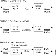 Diagram
The FastPAD meets the requirements of the ITU-T X.25 recommendation. It offers three types of X.25 interfaces (see the figure):
1. an interface with an X.25 subscriber,
2. an interface with a public packet switching network,
3. an interface to another FastPAD.
 X.25 Interface of the FastPAD
The behavior of the FastPAD in case of a protocol error depends on the type of interface. The selection of the type of interface is made in the configuration.
This interface is intended to connect X.25 subscribers to the FastPAD. There are two profiles available:
Profile 1: X.25 subscriber profile without additional services.
Profile 2: X.25 subscriber profile with additional services.
 X.25 Subscriber Interface
Profile 1 offers the following services:
The call confirmation packet format and the reset sent by the FastPAD are reduced (no address and no additional services).
Profile 2 has the following services available:
The call confirmation packet format and the reset sent by the FastPAD are extended (additional services but no address service).
This interface gives the FastPAD direct access to a public switched packet network or across a switched circuit network. Two profiles are available:
Profile 0: | Direct access connection to a public network with additional services; the throughput class and the packet window size are set to 2. |
Profile 3: | Direct access connection to a public network without additional services; the packet window size set to 3. |
 Connecting to the PDN
These types of interfaces with a PDN (Public Data Network) need special address processing.
The public network considers the private FastPAD network as a subscriber. Addressing the interface of the public network is dictated by the public network.
With the "Compacting/decompacting" tables in the FastPAD, it is possible to translate a private network address (DNICZOAB) into a sub-address and vice versa.
To enable the FastPAD to determine the position of the subscriber, the user has to supply also the subscriber number on the public network.
So, when configuring the FastPAD, the user has to complete the compacting/decompacting tables (C11) and the PDN address table (C10).
The PDN address table gives information only about public networks where two addresses (called/calling) are used. The calling address identifies then the switch access point to the public network.
The numeration of the public network can be transmitted by:
1. Compacting/decompacting (class 12, parameter 52 = 1): see paragraph A.
2. address in call packet (class 12, parameter 52 = 4): The private network "calling" and "called" addresses are transported across the private network in the complementary address extension service using the DTE marker (see the X.25 recommendations).

The lines with the public data network have to be configured with parameter 52 = 4.
Node Zl puts the private addresses in the extension address facility field and adds the DTE marker. When the marker already exists, the addresses are inserted after the marker.
To be able to reach subscriber B, the private address of DTE B is translated into a public address using the called address inversion table for outgoing calls. This address corresponds with the public address of node.
On the outgoing side of the public network, node Z2 re-forms the calling and called addresses, using the extension address facility. When only the facilities with the DTE marker are transmitted, the marker is suppressed.
For the operator, this procedure is transparent and compatible with subscriber's use of DTE marker and address extension facilities at least when the maximum facility field size of a call packet is respected (See ITU-T X.25 recommendations).
This interface is intended to connect two FastPADs to each other, directly or via a modem.
When the FastPADs are connected via modems, an automatic backup via the PSTN can be made (see the figure).
The internal protocol assures the continuation of the communication in progress during the switch over to the PSTN and back.
Backup takes place transparently for the users of the network.
The Network Management System is informed of the switch over to the PSTN by the reception of an outstanding event, CT117 closed (CT117 = standby indicator).
Switching back is indicated by the opening of the CT117 contacts.
 FastPAD Interface
There are four profiles available:
Profile 4: | Inter node line, receiving clock signals (RC), circuits 114/115. The primary address = 0l and the logical channels are scanned in decreasing order. |
Profile 5: | Inter node line, transmitting clock signals (TC), circuits 114/115. The primary address = 03 and the logical channels are scanned in increasing order. |
Profile 20: | Inter node line with automatic backup via PSTN. The primary address = O1 and the logical channels are scanned in decreasing order. |
Profile 21: | Inter node line with automatic backup via PSTN. The primary address = 03 and the logical channels are scanned in increasing order. |
The X.25 protocol used between the FastPAD requires that certain Parameters (primary address, scanning direction of logical channels) are in reverse on both ends of one FastPAD link. Profiles 4 and 5, 20 and 21 manage these reversals.
The following diagram describes the steps = of the configuration process of an X.25 line, using the profiles.
Additional parameters can be configured according to the specific needs of each user.
Often modified parameters are the following:
The X.25 line parameters that can be modified are described in Chapter 4.
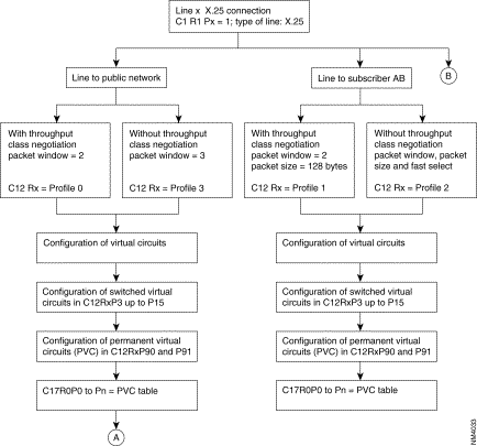 Configuration of an X.25 Line
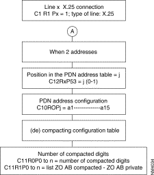 Configuration of an X.25 Line (Con't.)
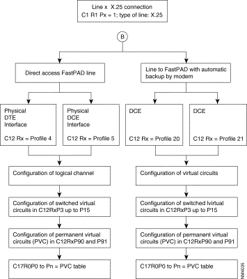 Configuration of an X.25 Line (Con't.)
With the FastPAD it is possible to connect three types of terminals to the X.25 network:
These terminals are managed respectively by the PAD (Packet Assembler Disassembler) and the VAP (Videotex Access Point) and PAD-M (Packet Assembler Disassembler Multistandard) functions of the FastPAD.
The protocols are defined in the recommendations:
· X.3, X.28 and X.29 for the PAD and the PAD-M. | |
· STUPAV/STUM, X.3, X.28 and X.29 for the VAP. | |
· X.3: | Defines parameters of the PAD in order to ensure optimum adaptation of the characteristics of the asynchronous terminal to those of the network. The values chosen for these parameters are associated with a line connected to an asynchronous terminal and defining the notion of profile. Each asynchronous terminal has a profile defined in the configuration (class 13). The meaning of each parameter is given in Appendix C. |
· X.28 | Defines the exchange procedure between an asynchronous terminal and the PAD to which it is connected. |
· X.29: | Defines procedure for the control of the PAD by an X.25 equipment in the case of a call between a synchronous terminal and the X.25 equipment. |
 Diagram
Asynchronous terminals can be connected to an FastPAD port directly (local) and remotely via a special link or via the PSTN. Multistandard PAD asynchronous terminals can be connected to an FastPAD port remotely via the PSTN
The terminal can be managed with the V.24 terminal interface or modem interface. Its two statuses can be:
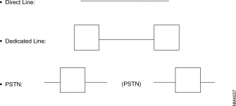
If the FastPAD equipment is configured with automatic speed recognition (RAV C12P4) and automatic parity recognition (RAP C12P28), the connection procedure is the following:
The cause of a repeated failure may be:
The logical connection established between the real terminal and the virtual terminal, managed by an application which is resident in the host. is realized by means of an X.25 virtual circuit.
The terminal or the host takes the initiative to establish the X.25 virtual circuit. In the case of VDMX terminals, the terminal takes the initiative to established the X.25 virtual circuit.
So we can classify the terminals as follows:
TTY = | Terminal managed by an operator or emulated software (virtual pc terminal): This terminal can transmit or receive the X.25 call. |
Minitel = | On a PSTN link: initiator and receiver of the call, |
| On a special or local link: initiation and reception of the call. |
LSCP = | Low speed computer equipment. This terminal receives the call from the network. |
LSCP-A = | Low speed calling equipment. This terminal transmits the call to the network. |
VDMX = | Multistandard Videotex Terminal: the multistandard PAD of the call initiator recognizes the standard use (Teletel, PRESTEL, BTX, multistandard or ASCII). |
 Management of the Logical Connection
Three possibilities are offered to establish a virtual circuit;
1. Addressed call: the X.121 address is indicated by the terminal according to the X.2B protocol. The VC is established in the following three cases only "call automatic" possibility is offered for a PAD-M:
 Presentation of a Network User Identifier (NUI)

 Using the Closed User Group (CUG) Optional Facility
2. Abbreviated call: the establishment of the virtual circuit is started by the terminal by transmitting a mnemonic to the FastPAD. The definition of the mnemonic is configured in the FastPAD.
3. Automatic call: the establishment of the virtual circuit is started by the FastPAD when the physical line is taken into service. The definition of the call linked with the line terminal is configured in the FastPAD.
It is advantageous to use the three methods mentioned above for the terminal types TTY and Minitel. With one configuration parameter the automatic call can be selected; the addressed and abbreviated calls are implicit when the automatic call has not been configured.
The mutual control between the PAD and the terminal is realized by the following mechanisms:
1. the XON/XOFF characters,
2. the interface signalling RTS/CTS,
3. the characters ENQ/ACK (Hewlett Packard protocol).
To configure an asynchronous line the following types of terminals can be selected:
1. 1) TTY terminal; XON/XOFF or/and RTS/CTS,
2. 2) HP terminal, ENQ/ACK,
3. 3) LSGP/LSCP-A terminal; XON/XOFF or RTS/CTS (local).
The set of X.3 profiles is according to ITU-T. Thus, an asynchronous line can be predefined with the X.3 parameters, adapted to the desired configuration.
Two extra facilities are offered by the FastPAD:
With each physical connection between the terminal and the FastPAD equipment, the line profile defined during configuration (class 13) is put into service. This profile can be modified by means of X.28 commands or upon reception of an X.29 message.
The X.28 procedure determines the commands accessible via an asynchronous terminal intended for the PAD to which it is directly connected. These commands are the following:
| Commands | Function | Response of PAD |
|---|---|---|
STAT | Request for status of virtual call between PAD and terminal | ENGAGED = VC established FREE = VC not established |
CLR | Request to clear call | CLR = call cleared |
PAR? No. of parameters | Request for value of one or more parameters EX: PAR? 1, 2, 5 Note: To determine the values of all the parameters, simply type PAR? | Parameters followed by their value EX: PAR 1: 0.2 : 1.5 : 1 |
SET? No. of parameters new values, etc. | Modification of value of one or more parameters EX: SET? 1: 0.2 : 0.4 : 3 | Parameters followed by their new value EX: PAR 1: 0.2 " 0.4 : 3 |
PROF Profile number | Choice of a standard profiles |
|
RESET | Resetting of a call |
|
INIT | Sending of an interrupt |
|
MSET? No. of parameters | Generation of PAD message for positioning of parameter | None or ERROR if refused by far end |
MPAR No. of parameters | Generation of PAD message for positioning of parameter, reading of parameter of far end | Parameters followed by their values |
RSET? No. of parameters | Generation of PAD message for positioning of parameter | Non or ERROR if refused by far end |
RPAR No. of parameters | Generation of PAD message for positioning of parameter, reading of parameter of far end | Parameter followed by their value |
The FastPAD equipment manages the "PAD messages" transmitted by the remote synchronous equipment, except for redial request messages.
The error correction procedure is a service offered by the YAP (Videotex Access Point) function. It corrects errors which are introduced by the network (PSTN) on the 1200 baud-channel of the VAP-terminal (minitel) connection.
There are two types of error corrections. Which one is used depends on the mode of the modem:
ECPN is activated (inactivated) on request of:
The ECPI is activated (inactivated) on request of:
The error threshold can be set with a configuration parameter: C12P90.
The transmission time-out of re-transmission requests (ECPN) is set with configuration parameter: C12P91.
When the request for the identification of a terminal on a PSTN line is configured (C12RiP39 = 10),The user must enter an NUI ON or NUI OFF command before the setup of any call.
The NUI ON command allows the entry of an identification (up to 15 decimal characters) which becomes the "calling" address in the transmitted call request packets.
The NUI OFF command is used to position the "Reverse Charging" (RC) facility in the call request packets.
When the user tries to set up a call without having first entered an NUI ON or NUI OFF command, the physical path is cut off.
The following diagram describes the phases in the configuration of an X.25 line using the profiles.
Many additional parameters may be configured depending on the specific requirements of each user.
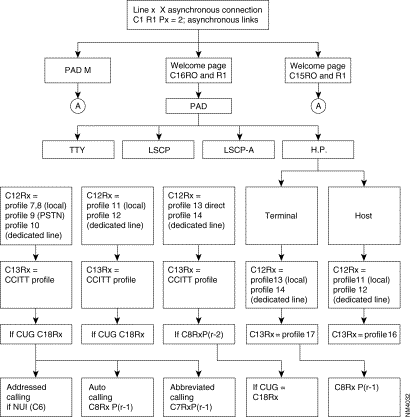 Configuration of an Asynchronous Line
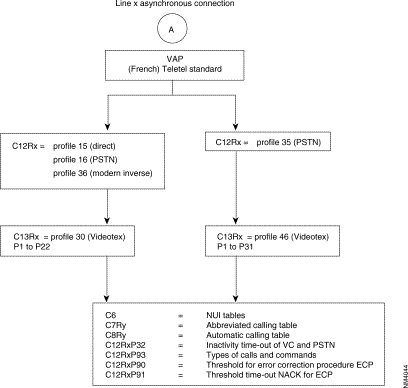 Configuration of an Asynchronous Line (Con't.)
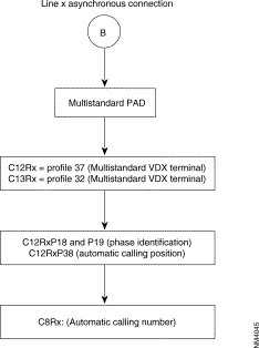 Configuration of an Asynchronous Line (Con't.)
The SLIP (Serial Line Internet Protocol)/PPP (point-to-Point Protocol) asynchronous interface allows the transparent handling of SLIP or PPP frames.
These frames are made up of asynchronous characters fLANked by termination characters:
At the X.25 packetizing level, only the second termination is a data input criterion, the first terminator being packetized at the beginning of the packet with the other bytes.
Two asynchronous profiles allow the use of these protocols
These profiles correspond to fixed values of X.3 parameters (except for parameters 2 (echo) and 6 (indications).
They may be used either at the configuration level (class 13, parameter 0) or dynamically with the X.28 "PROF" command followed by the profile number for the desired protocol.
Restriction
The values of the X.3 parameters must not be modified (except for parameters 2 and 6) by configuration.
It is possible to connect equipment of the type SNA to an X.25 network. SNA (System Network Architecture) is a system introduced by IBM.
The FastPAD assures the transport of the SDLC protocol (SNA, level 2) in the X.25 network.
The implementation of that transport is in accordance with the one accepted by IBM. This means that a "Logical Link Control" layer (LLC) is used under SDLC to transport the controller information.
There are two LLC protocols available:
That is why it is possible to have, for example, on one side a cluster controller (SNA node, type T2.0 or T2.1) connected in SDLC to a FastPAD and on the other side an SDLC host (SNA node, type T4) or X.25-NPSI.
The figure shows an example of the standard architecture for this type of network
 Example of Standard Architecture
To assure the transport of this protocol there are two types of interfaces available in the FastPAD:
This interface is intended to connect an IBM front-end Host computer (primary SNA node). It is called "SDLC Front-end". It can emulate a multipoint controller connection. The profile available for this type of interface is:
This interface is intended to connect the terminal controllers (Clusters; secondary SNA nodes). It is called "SDLC Remote". Each interface of this type can serve several multipoint controllers.
The profile available for this type of interface is:
The diagram describes the steps of the configuration process of an SDLC line, using the profiles.
Additional parameters can be configured according to the specific needs of each user. Details of the parameters are described in Chapter 4.
 Configuration of an SDLC Line
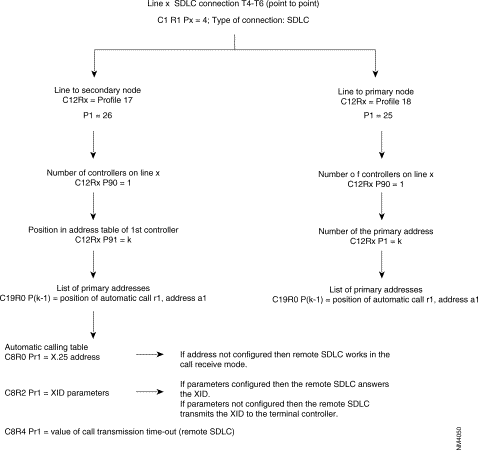 Configuration of an SDLC Line (Con't.)
The FastPAD can be connected to a packet switching network and to a circuit switching network. There are three connection possibilities:
EBS: Synchronous Standardized Input. An X.25 subscriber is connected across the switching circuit network to the FastPAD. Only incoming X.25 calls are accepted. The modem operates in automatic answering mode.
 Modem Operation
 Modem Operation
Conversion of the numeration between the FastPAD and the PSTN is necessary.
These services offer many applications.
Following two examples:


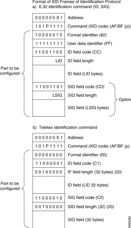 Diagram
In Case of a failure of the network (congestion, line or equipment failure), the FastPADs automatically establish a circuit via the PSTN.
To facilitate the configuration operations of the PSTN lines there are two profiles available in Cl2 and four in C13:
In class 12:
| Profile Nos. | For PSTN Lines |
|---|---|
40 | DTE PSTN back-up with V.25bis modem |
41 | DCE PSTN back-up with V.25bis modem |
In class 13:
| Profile Nos. | For PSTN Asynchronous Lines |
|---|---|
40 | PSTN back-up with V.25bis SBS |
41 | PSTN back-up with V.25bis EBS |
42 | PSTN back-up to V.25bis SBS + XID |
43 | PSTN back-up to V.25bis EBS + XID |
The following diagram gives the steps in the configuration process of a PSTN line using the standard profiles.
Additional parameters can be configured according to the specific needs of the user. The following parameters are often modified:
For a more detailed description of the parameters see Chapter 4.
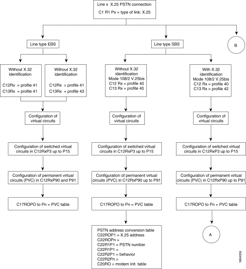 Configuration of a PSTN Line

 Configuration of a PSTN Line (Con't.)
 Configuration of a PSTN Line (Con't.)
Equipment of the type DSA can be connected to the FastPAD. DSA (Distributed System Architecture) is a network architecture introduced by Honeywell Bull.
The FastPAD assures the local emulation of the character synchronous VIP procedure (VIP = Visualizing Interactive Procedure) and the transport of the information messages.
The FastPAD network is transparent to the multipoint VIP link without reconfiguration of the Honeywell Bull equipment. The figure gives the standard architecture for this type of network.
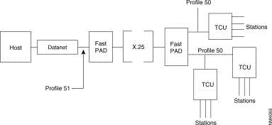 VIP Architecture
VIP architecture:
Datanet | = | Front-end for the central system (Host); |
TCU | = | Terminal Controller Unit |
Station | = | Terminal (Screen + printer). |
To assure a protocol transport, there are virtual circuits established between the two available types of interfaces in the FastPAD:
This Interface, intended to connect the Bull Host front-ends, is called: HPAD. It can emulate a multipoint controller connection.
The profile, available for this type of interface, is:
This interface, used to connect the terminal controllers, is called TPAD. Each interface of this type can support several multipoint controller connections.
The profile. available for this type of interface, is:
For each TCU an address is assigned.
The list of addresses of the terminal controllers. present on the VIP line, has to be configured in C13 of profile 50 (predefined list of station addresses).
For each TCU. that can be contacted by the host. the X.25 address of the corresponding HPAD interface must be known before the virtual circuit can be established (per station or per controller).
Thus, configuring the VIP protocol, the user has to complete the controller address table (C19) and the automatic calling table (C8).
The following diagram gives the steps in the configuration process of a VIP line using the standard profiles.
Additional parameters can be configured according to the specific needs of the user. Details of the parameters are described in Chapter 4.
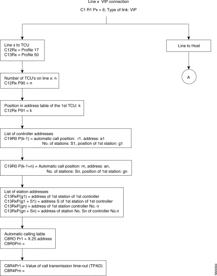 Configuration of a VIP Line

Equipment of the type BSC 2780/3780 can be connected to the FastPAD.
The FastPAD assures the local emulation of the character synchronous BSC 2780/3780 procedure (BSC = Binary Synchronous Communication) and the transport of the data messages.
The FastPAD network is transparent to the multipoint BSC link.
The figure gives the standard architecture for this type of network.

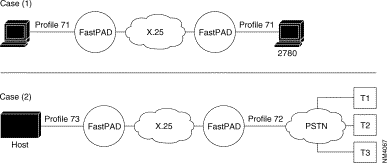 Standard Architecture
PSTN = Public Switched Telephone Network
CPU = Control Processor Unit
To assure the data transport of this protocol, a virtual circuit is established between the two types of interface, available on the FastPAD equipment:
This interface connects the BSC 2780/3780 equipment! that requests e transfer. With BSC 3780 it is possible to emulate several terminals via the PSTN; in that case the identification of the terminal has to be managed.
The available profiles for these types of interfaces are:
This interface is used to connect the BSC 2780/3780 equipment that receives the transfer request. The identification of the terminal has to be managed when the "calling" side connects several BSC 3780 terminals via the PSTN.
The available profiles are:
To enable the establishment of a virtual channel, it is necessary for the BSC 2780/3780 "calling as well as "called" side to know the X.25 address of the corresponding interface.
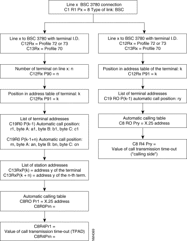
For that reason, the user has to configure this in the "automatic calling table" (classes 8 and 19) and if also the terminal identification has to be managed they have to be configured in class 13, profile 70.
The following diagram gives the steps in the configuration process of a SSC 2780/3780 line, using the standard profiles.
Additional parameters can be configured according to specific needs of the user.
Details of the parameters are described in Chapter 4.
 Configuration of a BSC 2780/3780 Line
Equipment of the type BSC 3270 can be connected to the FastPAD.
The FastPAD assures the local emulation of the character synchronous BSC 3270 procedure (BSC = Binary Synchronous Communication) and the transport of the data messages.
The FastPAD network is transparent to the multipoint BSC link. The figure gives the standard architecture for this type of network.
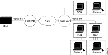
TCU | = | Terminal Controller Unit. |
Station | = | Terminal (screen or printer) |
To assure the data transport of this protocol, a virtual circuit is established between the two types of interface. available an the FastPAD equipment:
The interface, connecting the host interfaces, is called HPAD.
It emulates a multipoint connection of the controllers.
The available profile for this type of interface is:
This interface, connecting the terminal controllers, is called TPAD. Each interface of this type supports several controllers in a multipoint connection.
The available profile for this interface type is:
The address list for the terminals present on the BSC line must thus be configured in C13 profile 60 (predefined station address list).
Each terminal controller that wants to connect to a host, must know the X.25 address of the corresponding HPAD interface, to be able to establish a virtual circuit for each station or for each controller.
For this reason, the user has to configure the controller address table in class 19 and the automatic calling table in class 8.
The following diagram gives the steps in the configuration process of a BSC 3270 line, using the standard profiles.
Additional parameters can be configured according to specific needs of the user.
Details of the parameters are described in Chapter 4.
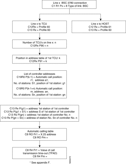 Configuration of a BSC 3270 Line
The transparent BSC (BSC-T) function is used to connect most variants of the BSC protocol through an X.25 network.
The chosen principle consists in detecting frames on the physical connection, packetizing them, directing them to an X.25 network, and transmitting them as they are to the remote BSC-T connection.
No local emulation of the BSC protocol takes place; hence there is no sensitivity to procedure variations and only the format of the frame has to be recognized.
Similarly, cyclic redundancy is not checked, and is carried without transformation in order to optimize the processing time in the concentrator.
What remains then is to ensure the possibility of recognizing the frame formats of the varying BSC standard protocol. This is achieved by the configuration of class 13 which, within the limits of the adapted structure, enables the recognition of most BSC type frames.
The configuration of this class is of primary importance for frame recognition, as configuration errors could lead to non-recognition of certain frames or erroneous interpretations of frames resulting in truncated frames.
Profiles exist; their suitability for the connected protocol must simply be ascertained.
It is possible to depart from the values given in the profiles. It is recommended that the validity at a profile of a modification for a given case should be checked out with the Cisco user support department.
In any case. responsibility for the selection of profiles or modifications in relation to profiles falls on the person making the configuration choices.
 BSC-T Connection in a Network
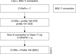
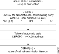
Two parts may be distinguished in the configuration of BSC-T connections:
These configurations follow the pLAN given in the block diagram below.
It is possible to modify the parameters of the connection given by the profiles, in Class 12 and 13.
Details about the parameters of Classes 12 and 13 are given in Chapter 4.
The securized virtual circuits offer the following functions:
For the user this service is transparent.
This securized service can be used for all transmission protocols as well as for the management functions.
To use this facility the following parameter value has to be set to "1":
The configuration manual gives the other possible values for securized virtual circuit.
When this parameter is set to "2", securization is not allowed. Each attempt to establish a securized virtual circuit results in clearing the subscriber.
When parameter 94 = "3"the securization is filtered. Generally, only the subscriber lines can be securized.
Filtered securization of a line can be used as shown in the following example:

Calls transmitted by the subscriber to his usual network are securized. Calls to another network are not securized. This possibility is offered only in the direction from subscriber to filtered line and if the securized subscriber and the filtered line to the other network are connected to the same FastPAD.
If the calls transmitted by the subscriber are not reliable, but if he can receive reliable calls, then parameter 94 has the value 3.
For routing
Barring exceptions (responsibility of the operator), these parameter should not be modified (class 24, recurrences 0 and 1).
The network virtual circuit is re-established when the calling securized party sends a new call packet, while, during the re-connection time. the securized called party waits for the call reception.
· number of call repeats: | C24R2P20 |
· "slow call" time-out: | C24R2P21(x l sec) |
It is possible to speed up the re-connection by configuring a lower value for the "slow call" time-out (recommended value: minimum 2 sec), but the processor load will increase at the cost of other FastPAD users.
Also the "wait for re-connection" time-out (default: 2 minutes) and the "number of call repeats can be changed.
When a clear of the network takes place, the call is re-transmitted after expiration of the "slow call" time-out.
Data recovery takes place after each re-establishment of virtual circuits but also when a network reset is received. However. the maximum number of recoveries is limited; it can De configured as follows:
The "fast select" facility is used by default by the securized virtual circuits though it can be "switched off" if the operator desires.
In that case, a supplementary packet has to be transmitted and the time to establish or to re-establish a securized virtual circuit is extended.
· "Fast select": | C24R2P54. |
It is possible to modify the transport window. The default value is "10". This rate is valid for the entire FastPAD, not only for the securized lines.
· Transport window: | C24R1P35. |
When it has not been possible to re-establish a connection, the X.224 and 8073 standards propose to wait (to freeze) for 2 minutes before using the reference number again. This time-out can be configured:
· Freezing time-out: | C24R1P23 (x 10 sec) C24R2P23 (x 10 sec). |
Address conversion can be configured the same way as it is configured for an X.25 line (C24R1P89).
However, the subscriber call request packet may be thus converted only:
The subscriber call packet has no address conversion in the X.25 network but only on both ends.
Only the call packet transmitted on a securized virtual circuit is converted, this packet is only intended for the "called" securized virtual circuit.
The securized function is configured with a certain number of logical channels (maximum number of securized VCs), the same way as for an X.25 link.
Modification of the number of logical channels is carried out the same way as for an X.25 link (class 24, recurrences 1 and 2).
Address conversion can be configured the same way as it is configured for an X.25 line (C24R1P89).
The packets transferred in the TPDU are configured with a size of 128 bytes (by default). A packet containing more than 128 bytes is split up.
Only in exceptional cases this value should be changed (because it must be the same in the entire network). in that case it should be configured in C24RlP62 to 67 (ESV/N4) and the double value in C24R2P62 to 67 (IR).
It is possible to subscribe to the reliable virtual circuit service for connection lines grouped under the same address, even if the lines are located on different modules at a unit or of several units.
The distribution of calls to the lines then takes place using equally shared routing, for example.
During e recall, the distribution conditions are often different from those of the initial call, and the reliable virtual circuit service must receive the new call on the same module as the initial call.
If the distribution of lines exceeds 1 module, the network interface must subscribe to the callback feature: C24R2P81 = 2 as must the links between the units.
This service is not available with management functions.
Frame relay (FR) is a frame mode transfer service for long distance communication (WAN: Wide Area Network). This service is based on the modified LAP-D structure (LAP-D: Link Access Procedure on D-channel). The term LAP-F stands for: LAP for Frame mode support services. LAP-F data is multiplexed on (OSI) level 2.
Signalling relative to this service is managed by the LMI function (Local Management Interface = ITU-T Q.933, Appendix A and ANSI T1.617 Appendix D of this manual).
LAP-F = ISO standard Q.922.
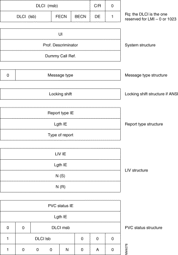
There are two types of frames:

Legend
DLCI | = | Data Link Connection Identifier |
DE | = | Discard Eligibility bit |
BECN | = | Backward Explicit Congestion Notification bit |
FECN | = | Forward Explicit Congestion Notification bit |
C/R | = | Command/Response indication bit |
msb | = | Most Significant Byte |
lsb | = | Least Significant Byte |
CRC | = | Cyclic Redundancy Check |
A local management interface of the frame service is offered. It enables a subscriber to determine the status of the PLLs of the network and prohibits him from using a PLL which is not available. It supplies the procedures making it possible to detect and modify the following events:
For this purpose, the LMI of the subscriber (subscriber LMI) regularly transmits status enquiry messages. The LMI of the network (network LMI) replies with status report messages.
Two standard protocols are used for the local management interface:
FRTE: | FR Interface which acts like a terminal with regard to network; it supports the FRI, FRSNA, FRIP and FRT Frame-relay stack. |
FRCE: | FR interface which acts like a network with regard to a subscriber; it supports the FRA Frame-relay stack. |
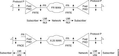 FastPAD Configuration as Subscriber LMI (UNI) or Network LMI (NUI)
The FastPAD can be configured as a subscriber LMI (UNI) (when it is facing an Frame Relay network), or a network LMI (NUI) (when it is facing an FR subscriber).
PLL = Permanent Logical Link
Sub-layer FR2.0 is the relay service. It manages only the bits representing the DLCI number in the heading.
Sub-layer FR2.1 is the frame switching and network congestion service. It manages the FECN, BECN, DE and C/R bits. RT2.0 and RT2.1 represents the core of Q.922.
Sub-layer FR2.2 represents the entire protocol as defined in Q.922. This protocol is generally active in the network periphery in the subscriber terminals.
The FastPAD equipment offers several types of interfaces:
A) The subscriber Interface
B) The Network Interfaces (FRTE)
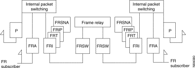
The following diagram gives the steps in the configuration process of a frame relay switch interface for an incoming and an outgoing line and using the standard profile.
Additional parameters can be configured according to specific needs of the user.
Details of the parameters are described in Chapter 4.
The two lines to be configured have to be on the same module.
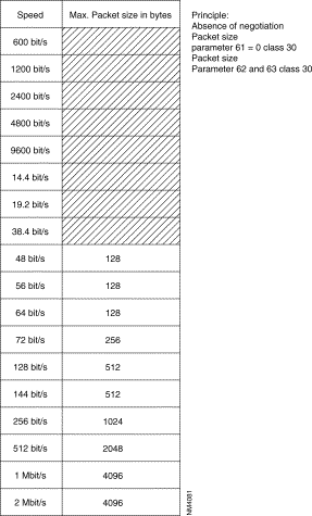 Speed versus Max. Packet Size
 Configuration of Frame Relay Lines
The following diagram gives the steps in the configuration process of an HDLC or frame relay subscriber Interface using the standard profiles.
Additional parameters can be configured according to specific needs of the user.
Details of the parameters are described in Chapter 4.
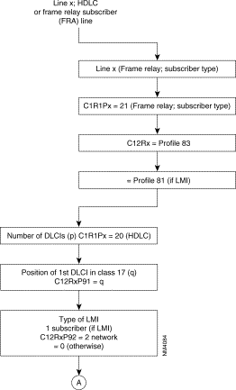 Configuration of an LDLC or Frame Relay Subscriber (FRA) Line

As these PLLs have no implicit physical output port, at least one frame relay line In class 1, recurrence 1 has to be configured 18 (frame relay) enabling the routing tables to be configured in class 32.
The frame relay physical lines have an 84 profile (DTE) or 85 profile (DCE) defined in class 12. For these two profiles, only the parameters related to the physical line level are significant and possibly an 84 profile in class 13 which defines the LMI parameters (LMI is optional). LMI is not offered for transit couples (FRSW).
In class 30, the connection parameters of levels 2 and 3 of each PLL are defined by means of profiles (see available profiles).
Class 32 represents the routing tables of all PLLs of the switch. There are two recurrences: one for incoming and one for outgoing lines. In each recurrence, the line number, the DLCI type and the DLCI number has to be configured.
The recurrence 0 describes the physical lines with the different DLCI numbers and their types.
Recurrence 1 describes the physical lines of the PLL: the PLL number and the recurrence of the profile defined in class 30 of the PLL are indicated.
REMARK: For simplification, it is recommended that the virtual line number and the DLCI number of the PLL should be made equal on the physical line.
This rule is applicable, for adjacent nodes in which, as in this example, line 160 should have an odd profile number. this departs from the FastPAD rule.


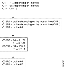
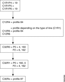
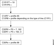
 Example of FNA/FRA Configuration
This local (AB SA) is used to format the address of the called number in the call packet as follows:

REMARK: It is possible to choose to configure only a local (AS) in C17 with all the restrictions that this implies. The calling address in the call-request packet then has the following form:


 FRSNA Example
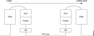

The SEP field of the multiframe protocol is negotiated between FRA. It is thus optional.


REMARKS
1. In these two examples, the X.25 VC encapsulated in FR is established end to end between two network elements via the FRA protocol.
2. In the following cases, the internal VC is established locally on each machine between the subscriber protocol (FRA, "P", SDLC, S.25, IP) and the protocol offered on the network interface (FRSNA, FRIP, FRT).


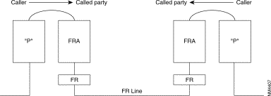


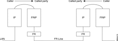

REMARKS
1. The FRI, FRSNA, FRIP and FRT stacks are represented by logic lines. As there may be several types of multiplexed stacks on a physical line, routing must be via the PLL ([65, 128] and [160, 239]) initialized in Class 32 Recurrence 1.
2. ZO (DNIC ZO AB) to PLL of normal/backup line output. The supporting VC (internal or external) is established by means of the routing tables (C9...). The end of the PLL allows the remote node to be identified by means of the associated ZO number. It is thus recommended that calls be routed by configuring the ZO of the remote equipment.

Example of routing table for PLL linking switch ZO = 00 with ZO = 01.
Routing table of switch 00:
Routing table of switch 01:
When several PLLs use different protocols, it is recommended that these internal VCs be routed by using different ZOs (one ZO per PLL) or routing at the level of the AB.
The ISDN function connects, in X.25 mode, the terminals of the FastPAD switches to the remote subscribers via the ISDN.
The FastPAD equipment meets the ITU-T requirements concerning ISDN (1430-1431, l440-l44l and l450-1451). The interface used gives access on S0-basis in user mode.
The remote subscribers can be:
X.25 data transfer takes place on one of the two B-channels of the S0 interface. This service is provided by Permanent Logical Links (PLLs) established at the S0 interface. Four PLLs are offered per subscriber access with a maximum bit rate of 9600 bit/s.
Data transfer is also offered without signalling.
The ISDN function provides for the backup or overflow of a dedicated line (LS).
The figure below shows the possible ISDN connections.
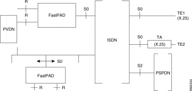
Legend:
TA | = | Terminal adapter |
PVDN | = | Private Data Network |
PSPDN | = | Packet Switched Public Data Network |
ISDN | = | Integrated Services Digital Network |
S0 | = | Basic interface (two B channels, one D channel at 16 kbit/s) |
S2 | = | Primary interface (thirty B channels, one D-channel at 64 kbit/s) |
TE1 | = | Terminal, representing an S0 interface |
TE2 | = | Terminal. representing an R-interface, connected to a terminal adapter |
The operator has to configure the number of B-channels (0 up to 2) which have to be managed in class 12, parameter 56.
The X.25 configuration parameters of the B-channels (this is in class 30) are dynamically allocated at the moment the connection is made. The standard profile of a D-channel for signalling is profile 47.
The E.164 address consists of an E.164 number and possibly a subaddress with up to 4 digits.
The operator can also choose the number of PLLs declared at the S0 interface (C12 P43) as well as the connection parameters defined in C30.
The available services are:
Terminals connected different ways to the ISDN can access to the FastPAD network via the ISDN by means of the FastPAD. The access of a PSPDN subscriber to a FastPAD network via a PLL is described in the section "Normal output" of this chapter.
In such an application, the call is transmitted by the terminal. It is received by the FastPAD via the signalling procedure of the D-channel. If possible, the FastPAD accepts the call and routs the call in the FastPAD network. After physical connection by the ISDN, the routing address is sent, being the X.25 protocol, by the calling terminal and by means of a standard call packet.
This type of application implies that the calling terminal transmits a double numeration: first one on the ISDN D-channel to obtain the FastPAD, then the second one on the B-channel of the X.25 FastPAD network to obtain the remote subscriber.

When the signalling detects an incoming call from the ISDN, the caller's identification procedure is initiated by checking the table in C22.
When the ISDN address of the caller is defined in C22, a recurrence number in class 30 is assigned to it; this recurrence defines the X.25 dynamic parameters used on the B-channel during the connection.
In C22R2 it is decided what actions have to be taken for known and unknown calling numbers. This could be:
The calling E. 164 address and the recurrence number in class 30 are remembered in case multiplexing has to be used on the D-channel. This is the case when more outgoing X.25 calls have the same E.164 destination address and the same dynamic X.25 parameters.
This service allows the connection of terminals, through a FastPAD network, to different users: the different possible accesses are:
In this type of application. the caller is the FastPAD network. It receives from the originating caller an X.121 address. Routing determines the S0 interface (S channel or PLL) on which the call is carried. In the case of B channel, the FastPAD converts the X.121 number into an El-4 address by means of a correspondence table.
In the case of a PLL, the FastPAD establishes the logical link if necessary (the connection parameters of the PLL are defined in C30).
The call-request packet is sent directly on the PLL.
It is also possible to send the E.164 address to the FastPAD in an X.25 call-request packet. In this case, the address must be preceded by a configured prefix and must be positioned in the called address as an X.121 address; the E.164 address should not be longer than 14 digits.
 Diagram
When the routing has selected an S0 interface to transfer the X.25 call, the following operations take place:
Multiple backup consists in associating with an X.121 number several ISDN numbers. It makes it possible to back up a dedicated line by means of different ISDN numbers and, preferably, on different nodes. It also allows the use of several interfaces in an MLP bundle.
If the ISDN interfaces are on different nodes, the variation in the cost of calls between two interfaces may be very large. It is necessary to associate with each lSDN number a priority configurable in C22R2 (action 7).
ISDN numbers are tried according to their priorities (the highest priority number is tried first). Likewise, an ISDN number must be tried several times before going on to the next node. The number of trials is configurable in C22R2 (action 5 or 6).
If all the tests with all the ISDN numbers fail, it is possible to restart another cycle of connection attempts. The number of cycles can be configured in C12 P67.
Three time-outs are configurable in C12:
The first two time-outs allow the time phasing of the different attempts.
The third limits the time of the different tests.
The duration of an attempt can vary and depends on the time-outs of the D protocol. It varies from a few hundreds of milliseconds to a few tens of seconds.
With this application two or more private networks are connected, permanently or as a back up, across an ISDN.
In this case it is an FastPAD module which is the caller. The decision to pass the call to the lSDN depends on the routing algorithm; the ISDN connection is considered as a normal physical connection. The following possibilities are offered:
The calls from the users are routed directly via the 5-channel; X.121-E.164 conversion is not necessary. This mode has to be used by the calling and called FastPAD in order to manage the allotment of the B-channels and to enable compatibility with the defined routing. The "connection/disconnection" outstanding event for a B-channel can be useful in this case.
When the physical link is established, the original call packet is transmitted via the selected B-channel. The second part of the FastPAD network makes sure that the call is routed to the final destination.

When a B-channel has been established to a given E.164 address, X.25 calls with the same E.164 address in the conversion table, are multiplexed via that B-channel. The other B-channel is only established when a different E.164 address is obtained or when there are no more free LCs On the first one, at least when overflow to the second channel is authorized.
The B-channel is disconnected when one of its virtual circuits is not active any more for a certain time. This time is configurable.
The ISDN can be connected as follows:
In each of the above mentioned configurations, the D-channel could be managing the permanent logical links (PLLs).
A) | S0 interface with two B-channels When the line number connected to the S0 interface (channel D) is "x" then the lines (x+1) and (x+2) are reserved for the B-channels. The other lines can be used for other purposes. |
B) | S0 interface with one B-channel When the line number connected to the S0 interface (channel D) is "x" then line (x+1) is reserved for the B-channel. The other lines can be used for other purposes |
C) | S0 interface without B-channel (packet mode in D only) When the line number connected to the S0 interface (channel D) is "x" then the line (x+1) can not be used. The other lines can be used for other purposes |
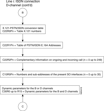
The following diagram describes the steps of the configuration process of an ISDN interface with D-channel without PLL and with or without (0 to 2) B-channels with or without PLL. Only the standard profiles are used.
Additional parameters can be configured according to specific needs of each user.
Details of the parameters are described in Chapter 4.

 Configuration of an ISDN Connection (Con't)

REMARKS: The parameters 22 and 23 define successively
The multiplication of the values of these two parameters defines the time between connection and moving into service of a B-channel.
The default values of these parameters in the standard synchronous profiles 4 and 5 are:
This makes the waiting time 2 x 3 = 6 sec.
When it concerns a connection to the ISDN, the physical circuits are reliable and there are no interface circuits. In that case it is possible to decrease the values of the 2 parameters, until they reach the value of the D-channel which is 400 msec. The recommended values are in that case:
Rerouting allows a server (called: the routing party) to select a received call and send it to another server (called: routed party), transparently for the subscriber.
The basic principles are the following:
The FastPAD offers the rerouting features according to two modes:
In both modes the rerouting function has two types of services:
The basic services as described in STURTEL are used. This includes the abbreviated names of the party (configurable), the message is rerouted to.
Two optional services are available, the same which are offered by TELETEL:
The parameters of the rerouting command are limited to 128 bytes if Fast Select is authorized on incoming/outgoing lines (C24R3P54 = 1). The rerouting function is available in all the nodes of the X.25 network. It is realized as an independent function establishing a connection between two FastPAD ports. The ports should manage the X.25 or the asynchronous (PAD or VIDEOPAD) protocol.
Access to the rerouting function is realized by subscription. For this purpose, the parameter of the line that received the call has to be configured:
C12P75 | = | 0; no rerouting |
| = | 1; rerouting |
or by using the following procedure:
The compression algorithm referenced LZ77 corresponds to Stac LZS compression. Stac is a registered trademark and LZS is a trademark of Stac Electronics.
This service makes it possible to reduce the length of the data in packets transmitted over the X.25 network between two switches. It is transparent for the subscriber and consequently be implemented whatever the type of subscriber line.
Entire sequences of packets (M bits) are managed so as to reduce the number of packets moving within the network.
 Diagram
Node = Host switch
The service may be established only between two users whose lines include compression subscription. All calls from a configured lines offer the service.
The subscription of a line for compression is defined by two parameters:
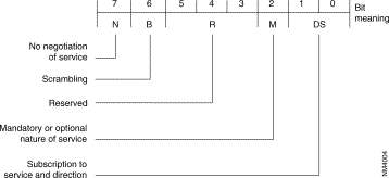 Configuration Parameters
 Configuration Parameters
This field determines first whether the line has a subscription (S = 1) or not (S = 0) to the compression service.
If yes, it indicates the direction in which it is implemented:
The field B indicates scrambled (B = 1) or unscrambled (B = 0) compressed data.
By default the compression service is negotiated between the Host switches (N = 0). Bit N allows the implementation of this service without negotiation (N = 1). In this case, buts D and S keep their meaning; bit M becomes imperative.
The grouping of packets makes it possible to concatenate in a packet leaving compression the result of the compression of several packets to be compressed, without Mbit.
The resulting packet is sent when it is full, or upon the expiry of a time-out if it is not full.
This service is de-activated during the processing of a packet sequence (M bit at 1), during which the management of the M bit for compression takes over.
The field RPQ indicates firstly whether the line is a subscriber (=0) or not (-0) for packet grouping.
If the line is a subscriber, this field also indicates the value of the time-out associated with this service. It is expressed in hundreds of milliseconds.
Possible values: 0 to 15
Default value: 0.
This parameter is significant only for compressed VCs established with equipment lower than V10.1 It indicates the period (in size of data to be compressed) of the compression rate measurement.
This measurement makes it possible to decide on possible resetting of the compression dictionary.
It is expressed in multiples of 32 bytes.
Possible values: 1 to 255 (32 to 8160 bytes).
Default value: 16 (512 bytes)
This parameter is significant only for compressed VCs established with equipment lower than V10.1
It indicates the ratio between the current compression rate and the maximum compression rate previously measured; below this ratio, the compression dictionary is reset.
It is expressed in percentage.
Possible values: 0 to 100
Default value: 90
Number of compression VCs managed on an FastPAD 1xx equipment or on the module 0 of an FastPAD 2xx equipment.
Number of compression VCs managed on module 1 of an FastPAD 2xx equipment.
Number of compression VCs managed on module 2 of an FastPAD 2xx equipment.
The implementation of compression requires the modification of these parameters and total reset of the equipment. The number of free buffers in the equipment depends to a great extent on these parameters (54 buffers per configured compression VC).
Possible values: 0 to 100 for equipment with 2Mbytes of RAM
Default value: 0
The management of the two different numbering pLANs (X.25 and PSTN/ISDN) enables a subscriber or a host to communicate with a remote subscriber connected to a grid X.25 network via a PSTN or ISDN network.
To provide this service, the original call request packet:
The Direction Management system extracts the PSTN/ISDN number as of the "called" X.25 address; the PSTN/ISDN number extracted is deduced from information configured in class 22:
The "ISDN/PSTN numbering pLAN "/"FastPAD address" adaptation takes place in association with the PDN processing (see corresponding chapter).
1. According to the X.121 address received, the PSTN or ISDN function carries out a search in the X.121 address table (C22 RO) to determine the additional information (C22 R2) making it possible to deduce, from the X.121 address, the PSTN or ISDN number.
2. If the extraction action is requested, the PSTN or ISDN number is extracted from the address field.
3. If a prefix elimination is defined in the X.121 address table (C22 RO), the prefix is eliminated from the PSTN or ISDN number extracted.
4. If the addition of a prefix is requested in the table of PSTN/ISDN numbers (C22 R1), the prefix is completed with the PSTN or ISDN number extracted (which may or may not have previously undergone elimination of the prefix).
5. The number of digits in the PSTN or ISDN number extracted is defined in the extraction action (C22 R2).
REMARK: The "called" X.25 address received does not undergo any modification after extraction.
Two subscribers A and B of two different private X.25 networks wish to communicate via the PSTN or ISDN network.

E: "Called" address
T: "Calling" address
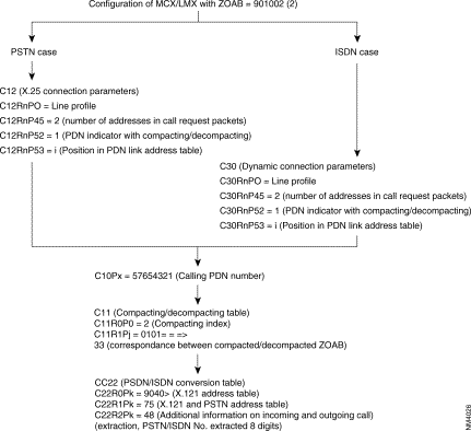 Configuration of FastPAD with ZOAB = 901002 (2)
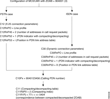 Configuration of FastPAD with ZOAB = 904001 (3)
1. The call request packet transmitted by A is in the following form:
2. The transmitted call has the following form:
1. The incoming call undergoes the following processing:
Processing of "called" address extraction (with prefix elimination/addition) at the PDN network interface does not allow restitution, in the confirmation packet of the "called" X.25 address of the original call request packet.
Consequently, the use of the reduced format (to 3 bytes) of the call confirmation is recommended.
When the complete format with address is used, the calling party receives in the call confirmation packet the "called party" address transformed into a "called party" PDN plus the compacted "called party" subaddress.
The structure of the called address field is in the following form:
 Structure of the Called Address Field
As the DNIC of the FastPAD numbering plan is fixed at 4 digits, the total number of digits in the PSTN/ISDN No. plus the SA should not be more than 11 digits.
The Direction Management does not manage the ISDN subaddress.
The FastPAD allows the connection of X.28 plus terminals to an x.25 network.
The protocols used for the management of these terminals are defined in recommendations X.3, X.29 and X.28 plus. The latter is very close to recommendation X.28 described in the section "X.25 Connection" of this chapter.
The terminal may be connected to the PAD directly, through a Dedicated Link or though a public switched telephone network (PSTN).
If the line is configured with Automatic Speed Recognition (ASR C12 P43), the user must enter a sequence enabling the PAD to define the line speed:
 Physical Connection of X.28 Terminals
Three possibilities are offered for virtual circuit establishment:
1. Addressed call
2. Abbreviated call
3. Automatic call
These commands are accessible via an asynchronous terminal intended for the PAD to which it is directly connected.
| Commands | Functions | PAD Response |
|---|---|---|
STAT | Request for status of virtual call between PAD and terminal | ENGAGED = VC established FREE = VC not established |
LIB or CLR | Request to clear the call | LIB or CLR = call cleared |
PAR? Parameter numbers | Request for value of one or more parameters Example: PAR? 1, 2, 5 Note: To determine the values of all the parameters, type PAR? | Parameters followed by their value Example: PAR 1: 0.2 : 1.5 :1 |
SET? Parameter numbers: new values, | Modification of a value of one or more parameters Example: SET? 1: 0.2 : 0.4 : 3 | Parameters followed by their value Example: PAR 1: 0.2 : 1.5 : 1 |
PROF Profile Number | Choice of a standard profile available in the PAD |
|
RESET | Reset of a call |
|
INT | Transmission of an interrupt |
|
MSET? No. of new parameter values | Generation of PAD parameter positioning message | None or ERROR if refused by the remote |
MPAR Parameter number | Generation of PAD parameter positioning message, reading of parameter from remote | Parameters followed by their value |
RESET? No. of new parameter values | Generation of PAD parameter positioning message | None or ERROR if refused by the remote |
RPAR Parameter numbers | Generation of PAD parameter positioning message, reading pf parameter by the remote | Parameters followed by their value |
D or DISC | Clearing of VC |
|
CONT | Return to transfer |
|
TPAR? Parameter number | Request for a value of one or more TELENET parameters Note: To determine the value of all the parameters, type TPAR? | Parameters followed by their value Example: TPAR 1: 0.2 : 1.5 : 1 |
ID (up to 15 digits) | Identification of PSTN network user | ERROR if string is wrong: alpha characters, plus 15 digits |
IDOFF | PSTN network user identification facility not used |
|
The following diagram describes the phases in the configuration process for an X.28+ line using the profiles.
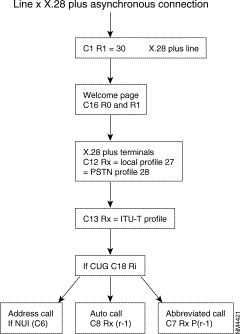 Configuration of an X.28 Plus Asynchronous Line
The management of switched lines (PSTN or ISDN) can be handled by the Dynamic Line Management function (DLM) incorporated in the equipment. It allows optimization of the use of switched lines for backup and for load overflow.
The DLM management function performs the following:
These services can, if necessary, be provided by FastPAD equipment without call interruption.
These functions may be supported by:
Two dimensioning optimization mechanisms (traffic overflow on switched lines) are offered:
The load thresholds for the overflow are determined, if the option is available, by means of load statistics through the analysis of line loading in time brackets of 24 hours.
In the absence of this option, the overflow load measurement mechanisms may be used independently in order to determine the loading thresholds.
In the event of excessive traffic on a line, it may be shared between this line and one or more other switched lines. Traffic sharing is handled using the X.25 MPL procedure. This overflow, local to a line, takes place without any interruption in the VCs established on this line.
In the event of excessive traffic on a line. the traffic can be switched over to a higher capacity switched line. Unlike overflow offered with the MPL procedure, this type of overflow is called CHANGEOVER. The VCs established on the changed over line are cut off. It is possible to mask the cutoff to the terminal equipment with the securized VC service.
Changeover takes place when all the VCs established on the line go through the same "access point" (example: front-end of a Host). This service can also be used for overflow for a line when MLP is not applicable (the remote equipment does not manage MLP).
Restriction: During the use of PLLs on the D-channel, the changeover is applied if all the VCs established on the PLL have been established on the initiative of the FastPAD.
Optimum use of switched lines is achieved by means of a set of basic services ("Toolbox") that may within certain limits be combined.
These services are as follows:
(*): limitations according to type of connection
The possible types of connection are the following:
Some services have restrictions depending on the type of connection and combinations of services are not offered.
For inputs, the use is identified by the standard elements of the ISDN access D protocol. These are the following:
These elements:
Identification and, consequently, combined use at input, is possible only on S0 eccesses incorporated in the equipment.
Access to switched lines may be handled by the DLM management function; this is done:
For each dedicated line of a node, the utilization conditions of the switched accesses for each DLM service must be specified. For this, the following information must be indicated for each line;
The list of switched parties is referenced by a unique X.25 address, which may be real or logic. This address is the switched network "Aimed Point" associated with the line.
It is possible to indicate, for each switched number associated with the aimed point, an associated behavior. This makes it possible to define:
The list of switched lines depends on the routing used and hence on the aimed point when the routing is carried out with the aimed point.
The DLM management function is called upon for routing.
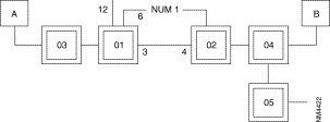 Diagram
S0 interfaces appear in the routing through the declaration of the two associated B channels.
Class 9 ZO unknown: | ZO = 04 |
| ZO = 02 - 4,6,0,3,49,13,14,7,8 |
| ZO = 05 |
3 = dedicated line
12 = S0 interface (12 D channel, 13 and 14 B channel)
06 = S0 interface (06 D channel, 07 and 08 B channel)
The DLM function is called upon for the backup of line 3. Call request packets are managed by DLM when line 3 is out of service.
To manage this backup, DLM knows the switched lines authorized (S0 6 and 12). The numbers to be used are defined by means of the switched aimed point associated with line 3. To accomplish this, in C12 R3. the remote equipment parameter delivers the position in C22 of the switched aimed point which corresponds here to the remote equipment.
 Diagram
DLM opens a 8 channel among the B channels of interfaces 6 and 12 with the number NUMl for the backup of line 3.
Routing with aimed point management associates the set of addresses with an equivalent address (called aimed point). Routing is then broken down into two stages:
With the same configuration as the preceding example, this results in the following:
 Diagram
The management of routing aimed points makes it possible to structure routing by stating that the access to nodes 04 and 05 takes place through node 02.
The configuration is simplified generally since, the only unknown ZO is 02 (immediate neighbor) and the only X.25/switched-number translation required is the address of 02, number NUM1.
The backups offered are the following:
Node (or combined line/node) backup is a basic offering through the integrated ISDN accesses thanks to the multiple backup. It is pointed out that in association with an X.25 address (or with a line through its associated switched aimed point), it is possible to define a list of switched network addresses to be used. This makes it possible, for example, to have a number to back up a line and in the event of failure (node out of service), to try another number in order to reach another node.
Centralized management of switched lines on these backup modes allows:
The implementation of backup by DLM is offered only in connection with the backup of a line and/or a node. It can be applied automatically on a call request packet or manually Upon authorization from a management central or from an operator.
This possibility is embodied in routing in accordance with the following general syntax:
<previous choice>, DLM, <SL-list,...>
with:
<previous_choice>: | Optional field designating, as applicable: a dedicated line or the main line of an MLP bundle. |
DLM: | Number of the DLM function (49 in decimal), |
<SL_list,...>, | Optional list of 1 to 5 switched lines of the unit, of the PSTN or ISDN type. In the case of ISDN, an S interface is designated by the contiguous list of its B channels or by the S interface itself. |
| <SL list,...> can be omitted only if <previous choice> is the PL of a bundle |
The routing configuration has the following form: class 9 rec xx: 4, nn, O,LL1,LL2,DLM,SL1,SL2,SL3...
where:
nn is the total number of lines.
When LL1 and LL2 are out of service, the call is transmi1ted to DLM. To back up the LL2, DLM uses one of the lines SL1, SL2 and SL3. The switched network number is deduced from the X.25 address regenerated by LL2.
Example: definition at lines:
0: | DL not forming part of an MLP bundle |
1: | DL main line of an MLP bundle |
2: | PSTN line |
3, 4, 5: | ISDN S0 interface (D channel + 2 B channels) |
6, 7, 8: | ISDN S0 interface (D channel + 2 B channels) |
9: | PSTN line |
160: | PLL on ISDN S0 interface |
The following combinations are considered valid:
0, 49, 2, 9, 160 | Line backup |
0, 49, 4, 5, 2, 7, 8 | Line backup |
160, 49, 3 | PLL backup |
1, 49 | Trunk line backup |
1, 49, 2, 4, 5 | Trunk line backup + node backup |
49, 7, 8, 4, 5 | Address backup |
The following combinations are wrong:
0, 49, 2, 4, 5, 7, 8, 9: | List of SLs limited to 5 elements |
0,49,4,2,5: | B channels must be contiguous |
0, 49,3, 6: | S interface must be designated by its B channels, |
2, 49, 4, 5: | < previous_choice > cannot be a switched line. |
The choice of this type of backup is obtained via the line, by positioning the behavior connection parame1er at "non-automatic backup". This type of backup must be configured on the two end switches of the link.
The opening of the backup can be authorized by modification of the behavior, or by a telemaintenance command indicating the switched aimed point associated with the line to be backed up. The line thus opened is closed automatically upon 0 VC detection. Calls to be backed up must consequently be sent before the expiry of the supervision time-out on the number of VCs.
The end of the backup, i.e. the disconnection of the switched lines opened for the backup. can be obtained automatically when the backed up lines go into service. The switched line centralized management system knows, for each line Opened, the switched network address of the other party. When a dedicated line goes into service and if the connection configuration of this line indicates "return to automatic backup", DLM closes all the switched lines whose destination address is included in the list of addresses of the switched aimed point associated with the line. The return of backup can be configured on both ends. It is possible to configure this service on only one of the two ends with certain restrictions when the switched accesses are not managed with the ISDN unit incorporated in the FastPAD equipment. The corresponding switched network must be known by the equipment to offer this service, which is not the case when it is called on the switched network on lines managed by PSTN modems or ISDN ATs. If the switched party is not known, DLM in any case does not cut off the established connections.
Load measurement is a service that can be used independently of load overflow. For each line, an outstanding event involving a threshold overshoot is generated when the measured load is higher than the upper threshold or lower than the lower threshold.
Outstanding events can be processed internally by the Dynamic Line Management function (DLM) and/or transmitted to a remote Network Management System.
The "upper threshold" outstanding event is repeated as long as the load is higher than the configured threshold.
The "lower threshold" outstanding event is repeated as long as a switched line of the "backup/overflow" (C12R5P128) type is connected.
In the case of an MLP bundle, it is sufficient that a line of this type be open for the outstanding event to be repeated with each consolidated measurement.
The transmission frequency for these outstanding events can be limited by a DLM management function parameter (C24R5P128). This parameter configures the time-out between transmission of two outstanding events concerning the same line (lower threshold and upper threshold).
Load measurement is carried out by the observation of traffic (transmit and receive directions) on the lines during a period of time. This may be configured (C24R5P127 in steps of 10 s) for all the lines.
For each line, the measurement of this period is compared with the associated thresholds. This comparison is made on the basis of the maximum incoming and outgoing traffic.
The use of a switched line to relieve the overloaded line (overflow) takes place when this comParison is positive n times consecutively. The parameter n can be configured for each line in C12RIP124.
The thresholds are expressed in occupation percentage. The calculation of the occupation percentage of a line is carried out using the speed declared during configuration.
For the integrated ISDN, the speed is fixed (64 kbytes) and not configurable; for this reason, the DLM management function does not take into account the configuration in calculating the occupation percentage of B channels.
For the cost of an S0 interface, it must be configured on the D channel.
The standard MLP procedure is located between layers 2 and 3 of Recommendation X.25. It enables an X.25 level 3 to use several X.25 level 2 (LAPB) and thus distribute the traffic of a call on several lines.
Maintenance of established calls during the disconnection of the line by the repetition of lost frames on another line or by waiting for reconnection of a line before interrupting the calls.

PL: | Principal Line (packet level active on this line) |
SL: | Secondary Line (no packet level active) |
P: | Packet |
F: | Frame |
L: | Line |
All the lines of a bundle must be on the same module.
A bundle is identified by the routing line Called the "principal line". The other lines are called "secondary lines". All the lines of a bundle (up to 8) must be located on the same module.
Backup and overflow of the lines of the bundle takes place without any virtual circuit (VC) break. In the case of remote equipment failure, backup is possible with VC breaks (possible use of securized virtual circuits).
The "line backup" service makes it possible to maintain the link between equipment by means of the remaining lines of the bundle or by opening an automatic or manual line.
Start-up and stopping of the "switched network line backup" service can be automatic or manual.
The opening of a switched backup in automatic mode is accomplished without a VC break and only when VCs have already been established in the bundle. The bundle is closed when no VC is established.
When subsequent calls are transmitted to the DLM function (routing configuration), a switched backup is opened to allow the reopening of the bundle.
Upon closing of the backup via the switched network without the use of the "automatic overflow" service, the opened switched line is closed upon a level 2 event on one of the secondary lines of the bundle in service.
When the automatic backup is used with the "automatic overflow" service, the cutoff of opened switched lines takes place according to the load. Automatic line backup must be configured on a single equipment (master).
This service allows overflow of part of the LS traffic of a bundle onto one or more switched lines. It may be manual or automatic (e.g. remote control from a Network Management System).
Opening and closing of switched lines in automatic mode takes place according to the bundle load measurement.
MLP bundle load measurement takes into account all the lines of the bundle whose level 2 is in service; it is carried out with the parameters of the principal line.
Only the maximum data rate of each line must be obligatorily configured in order to deduce the maximum data rate of the bundle. This is the sum of the bundle lines in service. The upper and lower thresholds as well as the consolidation configured on the secondary lines are not taken into account.
On each transmission of an "upper threshold" outstanding event, the DLM management function opens a switched line complying with the order of declaration of the lines in the bundle (C25). The opening of this switched line allows an increase in the maximum data rate of the bundle, leading la a atop in the overall load threshold of the bundle. Switched lines are opened one by one and their opening speed depends on the configuration of the load measurement.
When the dynamic link management (DLM) function is unable to connect a switched line in the trunk, a queuing time-out of 6 minutes (not configurable) is set. During this period, no overflow attempt is undertaken (upper threshold OEV ignored).
On each transmission of e "lower threshold" outstanding event, the DLM management function analyzes the possibility of closing the last switched line(s) opened. These lines are not closed under the following conditions:
MLP bundle consisting of an LS (main line of bundle) at 9.6 kbyte and an S0 access (2 B channels at 64 kbytes). The parameters for load measurement are:
P125 lower threshold: 40º/o
P126 higher threshold: 80%
P28 line speed: 10 (9.6 kbytes)
P124 consolidation: 2
P128......: 0 (LS)
Class 12 Secondary Line (D channel)
P128......: 1 (switched access)
For the other types of access, the line speed must also be configured.
P127 integration timing: 2 (or 20 seconds)

x: transmission of OEV + opening/closing
e: transmission of OEV
If automatic overflow has been configured:
Load > upper threshold LS = 7.7 kbytes opening 1 B channel
Load > upper threshold LS + 1B = 58 kbytes opening 1 B channel
Load < lower threshold LS + 1B = 58 kbytes closing B channel
Load < lower threshold LS =3.8 kbytes closing S channel
REMARK: If LS+ 1B: transmission of OEV lower threshold (LS + 1B) if load < 29 kbytes. Closing takes place if load < 3.8 kbytes.
The possibility of placing several switched lines with different addresses in an MLP bundle is used only when the switched access is capable of managing a list at numbers. In the event of failure on a number, the switched access must continue its connection attempts on the following numbers. It is pointed out that, as in certain modems and ISDN ATs, the FastPAD integrated ISDN access offers this service.
The sharing of switched accesses between several bundles is used only with the integrated ISDN accesses.
The changeover procedures can take place without a break in the call, using the securized VC service of FastPAD equipment. This service may, for example, be implemented on the "calling" or "called" subscriber connection equipment. The cutoff of a VC (line or node out of service in the network) is not immediately carried over to the subscribers. The "calling" subscriber equipment tries to reestablish another VC with the "called" subscriber connection equipment.
VC reestablishment takes place without any loss of data.
The use of centralized call management is mandatory for this service.
If a line is saturated, its traffic can be changed over to a switched line of higher capacity. Unlike the overflow offered with the MLP procedure, this type of overflow is called CHANGEOVER.
Changeover is caused by logically closing the saturated line. VC establishment must take place through the switched line opened for this purpose.

Under certain conditions, when all the traffic of a line converges towards a single access point, It is possible in the event of local saturation to change over the traffic from this line onto a switched line of higher capacity connected directly to the access point.
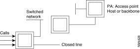
The conditions are:
On changing over to a switched line, the parameters of the switched LS are taken into account for load measurement on the switched line. This load measurement is carried out with consolidation, the lower threshold and the maximum rate configured on the switched LS. On the other hand, the upper threshold on a switched line opened for a changeover is managed with the parameters configured on this line (value of threshold), the only speed used is that of the switched line. (français: (valeur du seuil). seule la vitesse utilishée est celle de la LC). It is not useful in the case of a changeover to enter the parameters for threshold detection on the switched line. The only obligatory parameters are the maximum data rate and the cost.
For an S network managing the packet in D, load measurement takes place by PLL.
The operating mode described corresponds to the "automatic changeover" behavior configurable in Class 12 of each line (class 30 for the D-channel PLLs). The changeover must be configured on only one of the ends. This service allows the closing of an LS and complete changeover of its traffic onto a faster switched line as soon as the resources of the LS become saturated.
When the upper load threshold is reached, DLM looks in the routing configuration, using as reference the switched aimed point associated with the line, for the 4witched lines and the numbers that it is possible to use to carry overload changeover.
To accomplish this, it is mandatory for the routing of the switched aimed point to be of the type: <LS>, DLM, <SC>. <SC>.
When the connection of the switched line (SC) chosen is defective, dynamic line management (GDL) cuts off through a telemaintenance command the secondary line (LS) to be changed over. Putting this line out of service causes the clearing of all the VCs established. All callbacks are directed to the switched line by the routing configuration.
It is recommended, for callbacks, to use the aimed point routing in order to limit the configuration errors or, failing this, that the routing for these callbacks be also of the type <LS>, DLM, <SL>, <SL>...
When the lower load threshold (configured on original LS) is reached on the SL, the LS is reconnected to the disconnected SL. If it is not possible to reconnect the LS, the switched line is not disconnected. The 0 VG supervision mechanism for switched lines applies also for the switched lines opened for changeover. If a changed over LS goes into service this causes the disconnection of the switched line and consequently cancels the changeover.
The end having caused the changeover by opening a switched line (SL) and then by placing the overloaded secondary line (LS) out of service is not necessarily the one which receives the callbacks following the breaking of VCs established on the LS. Outside of the case of the integrated ISDN accesses (identification of caller), the called side cannot direct the callbacks to the switched line opened for this purpose.
Among the impossible combinations may be mentioned:
Routing with node and line backup DLM:
DLM is accessible through routing; its number is equal to 49. Network 9010. Backed up line: 3 node 03, backed up node: 02.
 Diagram
Class 9 ZO known: ZO = 02 -> 4, 6, 0. 3, 49. 13. 14, 7, 8.
3 = secondary line (LS)
12 = S0 interface (12 D channel, 13 and 14 B channel)
06 =S0 interface (06 D channel, 07 and 08 B channel)
DLM is called upon on a call request packet when line 3 Is out of service. A B channel among the B channels of interfaces 6 and 12 is used for the backup of line 3.
In class 12, recurrence 3, the remote equipment parameter (P129) provides the position in class 22 of the aimed point which, here, corresponds to the remote equipment.
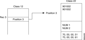 Diagram
In the same configuration as in the preceding example, it must be added that, in the line 3 connection parameters, the return of the backup is required (parameter 130 "behavior"). When this line goes into service, all the switched lines opened on the numbers NUM1 and NUM2 are cut off. The management of call backup by DLM is not necessary for this service.
All the equipment has the DNIC 9000
A and B are X.25 terminals subscribing to securized VC
N1: address E164 (ISDN) of the S0 interface on Z0 01, line 3.
N2: address E164 of S interface on Z0 02, line 4
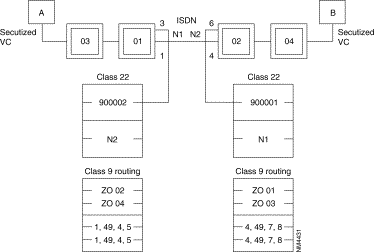 Diagram
In class 12 of line 1 of equipment 900001:
Number of consolidations: 2 (minimum)
Upper threshold: 70
Lower threshold: 40
Behavior: on-load changeover
Line 4 of equipment 900002 must be configured with an inactive behavior.
The "slow call" time-out of the securized VC must be more than Nsurv Tsurv of the changed over LSs because equipment 900002 does not detect the going out of service of LS 04 before this period of time during which all callbacks fail.
 Diagram
The use of the aimed point obviates the need to provide several inputs in the routing (and also in class 22) and consequently prevents configuration errors.
Consider two MLP bundles:
The two bundles share a switched line. All SLs are FastPAD integrated ISDN (S0 interface) accesses.
The configuration is the following:
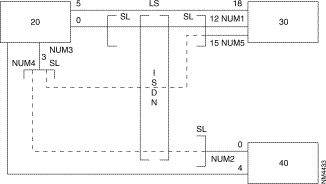 Diagram of Configuration
For each MLP bundle, it is necessary to give:
 Diagram
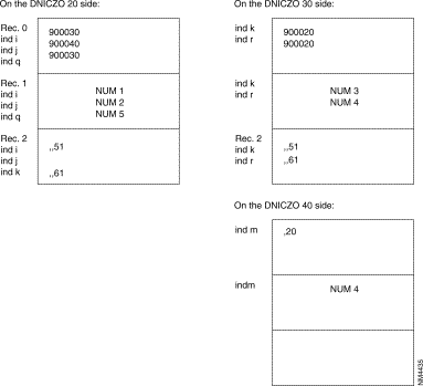
Load measurement configuration:
Node 20: | Class 12, line 5 |
Number of consolidations: | 3 |
Upper threshold: | 70 |
Lower threshold: | 40 |
Behavior: | Automatic overflow |
Node 20: | Class 24, rec 5 (DML parameterizing) |
Integration step: | 20 seconds |
128-kbyte line backup

Node 01: |
|
Line 3: | 128 kbyte LS |
Line 6: | Line not used |
Line 9: | S0 interface (09 D channel, 10 and 11 B channel) |
Node 04: |
|
Line 4: | Line not used |
Line 6: | S0 interface (6 D channel, 7 and 8 B channel) |
Node 02: |
|
Line 4: | 128 kbyte LS |
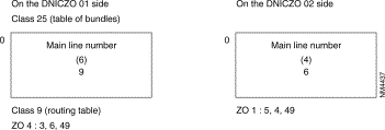 Diagram
If line 3 is out of service, routing transmits the calls to DLM when the bundle is inactive. DLM activates bundle 6 to transmit the calls. Subsequently, the calls will transit directly on bundle 6.
Like the IP stack used with the FastPAD product family, the SNMP stack is inherited from another device and fits a configuration structure based on Classes Recurrences Parameters(CRP). Because of this inheritance, configuration is very different from standard configuration. Also, on the profile used for this feature, all parameters—even those with a LAN comment in front—are not all relevant.
The following describes implementation, principles and configuration which are necessary in understanding and setting up the FastPAD for management using an SNMP manager.
The SNMP and IP routing feature are governed by the license "CLAN".
If administration functions of a homogeneous network such as DNA, DSA, SNA, are integrated within the communication architecture; the Simple Network Management Protocol (SNMP), defined in RFC 1157, provides a way of monitoring and controlling heterogeneous devices in local and wide-area networks.
SNMP servers are called Management Agents (MA) and maintain a set of structure tables containing information which may be requested by a Network Management Station (NMS) -also called client. Such information includes network operational reports and management capability.
The FastPAD supports the five SNMP V1 operations. There are two commands for obtaining information, one command to set variables, and a common response message to these commands. A separate command permits the agent to supply unsolicited information when a trap condition is encountered.
The FastPAD's implementation of SNMP meets requirements of MIB II (Management Information Base) according to RFC1213 for a limited number of objects.
The implemented MIB II objects are arranged into the following groups:
The detailed identification of objects in each of these groups is described in section "Group object" of this chapter.
Community names can be defined for Read-Only, Read/Write, and Trap.
Up to six different client addresses with level of access authorization can be defined.
Up to three different client addresses can be defined to receive trap messages.
The SNMP function above UDP works with an internal IP routing stack called Virtual Router (VR). This Virtual Router works internally according to RFC 1356. It means that independently of its own Host Id, it uses an X.121 address according to the internal numbering pLAN of the FastPAD family (DNIC ZO AB) and is reached using a Logical Link Connection (LLC) based on X.25.
This LLC is end-to-end over the network or local according to network topology and user's choice.
As any other entity, function or device used or connected to the FastPAD, the VR is identified by a subscriber number which maps with the Service Access Point (SAP) used by the Virtual Router.
This implementation is true for a module. So, in the case of a shelf system like the MP12 when rack-mounted, and the MPRxx, there are up to three SAPs per logical unit, one for each module.
SAPs are in fact seen as virtual lines.
The two next figures illustrate this concept.


Frip and Fra Frame-Relay stack make the translation between RFC 1490 and 1356.
The Virtual Router function (profile 112) is defined in Class 24 Recurrence X(6-8) and is governed by an optional software license. Corresponding code is CLAN.
The following Table 3-4 shows relations between modules, recurrences in Class 24 and SAP (virtual line).
| MO | M1 | M2 | |
|---|---|---|---|
SAP. virtual line | 60 | 61 | 62 |
Class 24 Rec X | 6 | 7 | 8 |
The subscriber number is assigned by using Parameter 46 in Class 24 Rec X.
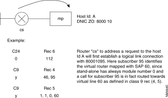
Example:


 C24

 Rec 6

 					Router "cs" to address a request to the Host Id A will first establish a Logical Link Connection 				with 80001095. Here subscriber 95 identifies the Virtual Router mapped with SAP 60, since stand-alone has always module number 0 and 				a call for subscriber 95 is in fact routed towards virtual line 60 as defined in Class 9 Rec(4,5).


 0
 112


 C9
 Rec 4

 y
 46, 95


 C9
 Rec 5

 y
 1, 1, 0, 60
Since shelf system uses up to three modules and each module has a specific Virtual Router, some tables must be shared. There are parameters that define the number of entries within tables and parameters to index the first entry within tables.
There are three parameters 27, 23, 26 in Class 24 Rec X(6-8) that are used to define routing.
A Virtual Router can have a different Logical Link Connection (up to 200). In Class 24 Rec X(6-8), Parameter 90 defines the number of LLC and Parameter 91 indexes the first entry in Class 17 Rec 0 where each LLC has a logical label Identifier (Id).
The structure of Class 17 Rec 0 is the following:
Figure 3-122 illustrates the principle in the case of an end-to-end X.25 LLC. This is also applicable in the case of FRI interconnection between FastPAD over a Frame-Relay network.
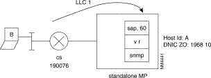
The VR on the stand-alone, using SAP 60 in this way, is identified as subscriber 54. The NMS B is able to send requests via the router "cs" using the LLC1 with the remote X.121 address 190076 (from the Mp point of view). The called address 19681054 is routed towards SAP 60.
C24 | Rec 6 for VR on M0 | C8 | Rec 0 | C9 | Rec 4 |
0 | 112 | 0 | 190076 remote x.121 @ | y | 54 subscriber 54 |
1 | 46, 54 subscriber 54 |
|
|
|
|
2 |
90, 1 1 LLC |
C8 |
Rec 1 |
C9 |
Rec 5 |
3 | 91, 1 First entry in C17 Rec 0 | 0 | 01, 80 | y | 1, 1, 0, 60 54 is routed on 60 |
|
| C8 | Rec 4 |
|
|
C17 | Rec 0 | 0 | 0 no slow call timer |
|
|
0 | 1, 1, 1 First entry in C8(0,1,4,5) | C8 | Rec 5 |
|
|
| LLC type is called LLC Id is 1 | 0 | CC, 08, 00 Ip NLPID for RFC 1356 |
|
|
NLPID stands for Network Layer Identifier Protocol.
One should know Frame-Relay configuration aspect, like encapsulation principle. For more details refer to the sections on Frame-Relay part and Encapsulation.
The following Figure 3-123 illustrates the case where the NMS works behind a router directly connected to the FastPAD. The reference point is from the type FRCE and the FRA stack will provide the Local Management Interface as a NUI.
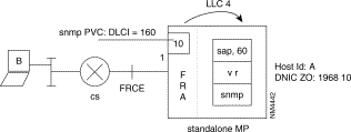
The NMS B will send requests to the SNMP agent via router "cs" using PVC 160. Port 1 is used for this connection and runs the FRA stack. Sub-interface 10 on port 1 is dedicated to PVC 160. The LLC has the Id 4 and is established locally from sub-interface 10 located on port 1 to SAP 60 represented here in this example by subscriber 71.
The following Table 3-5 shows the LLC configuration part.
| C 24 Rec 6 | C 12 Rec 1 | C 17 Rec 0 |
|---|---|---|
0 112 virtual router profile | 0 83 profile for FRA | 0 1,1,4 |
1 46,71 subscriber 71 | 1 90, 1 l LLC | 1: first entry in C 8 |
2 90,1 1 LLC | 2 91,2 second entry in C17 Rec 0 | 1: LLC type is called |
3 91,1 first entry in C17 Rec 0 |
| 4: LLC Id is 4. |
|
| 1 2,0,160,10 |
|
| 2: second entry in C 8 |
|
| 0: LLC type is calling |
|
| 160: DLCI 160 |
|
| 10: Sub-interface 10 |
| C 8 Rec 0 | C 8 Rec 1 | C 8 Rec 4 |
|---|---|---|
0 19681010 remote X.121 @ | 0 01,80 | 0 0 |
1 19681071 x.121 @ of the VR | 1 01,80 | 1 1 |
| C 8 Rec 5 | C 9 Rec 4 | C 9 Rec 5 |
0 CC,08,00 Ip NLPID for RFC 1356 | 9 10 subscriber 10 | 9 1,1,0,1 |
1 CC,03,CC Ip NLPID for RFC 1490 | y 71 subscriber 71 | y 1,1,0,60 |
One should know Frame-Relay configuration aspect, like encapsulation principle. For more details, refer to the section on Frame-Relay and Encapsulation.
The following Figure 3-124 shows the case where the NMS is located somewhere on the Frame-Relay network. The FastPAD is seen as a Customer Premise Equipment (CPE), the reference point is from the type FRTE, and the FRIP stack provides the LMI as a UNI.
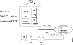
The NMS B sends requests via router "cs" which uses PVC 150 locally. At the remote point, the FastPAD uses PVC 300 on sub-interface 15 located on port 1. Sub-interface 15 can be reached internally via virtual line 170. In this example the VR uses subscriber number 44. The LLC Id is 2.
The following Table 3-6 illustrates this configuration part.
| C 24 Rec 6 | C 12 Rec 1 | C 9 Rec 4 | C 9 Rec5 |
|---|---|---|---|
0 112 Profile for VR | 0 84 (85) Profile for FRTE | 14 15 Subscriber 15 | 14 1,1,0,170 |
1 46,44 Subscriber 44 | y 44 Subscriber 44 |
| y 1,1,0,60 |
2 90,1 1 LLC |
|
|
|
3 91,1 1st entry in C17 Rec0 |
|
|
|
| C 17 Rec 0 | C 32 Rec 0 | C32 Rec 1 | C30 Rec 0 |
0 1,0,2 1: first entry in C 8 0: LLC type is calling 2: LLC Id is 2 | 0 1,,300 1: Port 1 300: DLCI 300 | 0 170,,300,0 170: vl_nb 170 300: DLCI 300 0: Rec 0 in C 30 | 0 121 Profile for FRIP
|
| C 8 Rec 0 | C 8 Rec 1 | C 8 Rec 4 | C 8 Rec 5 |
0 19681015 remote X.121 address | 0 01,80 | 0 1 Slow call timer | 0 CC,08,00 Ip NLPID RFC |
address |
| 0 1 Slow call timer | 0 CC,08,00 Ip NLPID RFC 1356 |
To be able to answer to SNMP requests the FastPAD needs a Host Id and a local Net Id.
The WAN IP address (Host Id) of the MP is defined in Class 31 Rec 7 while parameter 31 in class 24 Rec x(6-8) indexes the entry in this class.
Even if there is no physical LAN port, one must enter a LAN IP address in Class 31 Rec 8 and a local Net Id in Class 31 Rec(12-13). The LAN IP address is the same as the WAN IP address and belongs to the local Net Id, which is in fact, a range of IP addresses. For one given range (one entry in Rec 12, 13) the lowest Ip @ is set in Rec 12 while the highest is set in Rec 13.
For the SNMP application discussed here, this Net Id has in fact, a range of one IP address. This range will use the same IP address defined for the WAN and LAN.
Parameter 33 in Class 24 Rec X(6-8) indexes the entry for the LAN IP in Class 31 Rec 8 and its behavior in Class 31 Rec 11.
The structure of Class 31 Rec 11 is the following:
* for each entry there are 6 fields; the first field defines an entry index in Class 31 Rec(12-13), the other fields are not used and set to zero.
Ex: C 31 Rec 11
0 A,0,0,0,0,0
A: entry index in class 31 rec (12-13)
The following Figure 3-125 illustrates this principle.

From the NMS viewpoint the MP belongs to the Net Id A and its Host Id is 1. B sends requests via the gateway "cs" that establishes the LLC using the appropriate protocol.
The configuration is:
| C 24 Rec 6 | ||
|---|---|---|
0 | 112 | Profile for Virtual Router |
1 | 31,1 | first entry in C31 Rec 7 for the Wan Ip @. |
2 | 33,1 | first entry in C31 Rec (8, 11) for the LAN Ip @. |
| C 31 Rec 7 | ||
|---|---|---|
0 | 200,192,14,1 | Wan IP @. |
| C 31 Rec 8 | ||
|---|---|---|
0 | 200,192,14,1 | LAN IP @, which is the same as the Wan IP @C 31 Rec 11 |
0 | 1, 0, 0, 0, 0, 0 | 1: first entry in C 31 Rec (12,13). |
|
| f 0: not used. |
| C 31 Rec 12 | ||
|---|---|---|
0 | 200,192,14,1 | Lowest IP @ of the local Net Id. |
| C 31 Rec 13 | ||
|---|---|---|
0 | 200,192,14,1 | Highest IP @ of the local Net Id. |
By route, the Mp identifies a range of remote IP addresses mapped with an LLC Id. In Class 24 RecX(6-8) Parameter 28 defines the number of static route in Class 31 Rec 14 while Parameter 29 is an entry index in Class 31 Rec 14 which is used to link a range of IP address with an LLC Id.
The structure of Class 31 Rec 14 is the following:
* for each entry there are 3 fields, the first one defines an entry index in Class 31 Rec (12-13), the second defines the LLC Id and the last one is not used and set to 0.
Ex: C 31 Rec 14
In Figure 3-125 when the NMS B sends a request to the MP, the MP must send a response back to B using the destination address 194.10.20.10 that belongs to Net Id C. A remote range of IP addresses must be defined, as described in the next paragraph.
Figure 3-126 illustrates the case where:

The configuration will be:
| C 24 Rec 6 | C 31 Rec 7 | C 31 Rec 8 | C 31 Rec 11 |
|---|---|---|---|
0 112 Profile for VR 1 90,1 1 LLC 2 91,1 1st entry in C17 Rec 0 3 28,1 nbr of remote Ip range | 0 200,192,14,1 Wan Ip @ | 0 200,192,14,1 LAN Ip @ | 0 1,0,0,0,0 1: 1st entry in C31 Rec14 0: not used. |
4 29,1 1st entry in C31Rec14 |
|
|
|
5 31,1 1st entry in C31 Rec 7 |
|
|
|
6 33,1 1st entry in C31 Rec 8 |
|
|
|
7 46,40 Subscriber 40 |
|
|
|
| C 31 Rec 12 Lowest Ip @ | C 31 Rec 13 Highest Ip @ | C 31 Rec 14 | C 17 Rec 0 |
0 200,192,14,1 Local range 1 194,10,20,0 remote range | 0 200,192,14,1 Local range 1 194,10,20,255 remote range | 0 2,1,0 2: 2nd entry in C31 rec 12,13 1: LLC Id is 1. 0: not used | 0 1,1,1 1: 1st entry in C8 1: LLC type is called 1: LLC Id is 1 |
| C 8 Rec 0 | C 8 Rec 1 | C 8 Rec 4 | C 8 Rec 5 |
0 190076 | 0 01,80 | 0 0 | 0 CC,08,00 |
C 9 Rec 4 | C 9 Rec 5 |
|
|
y 40 | y 1,1,0,60 |
|
|
Figure 3-127 represents a case where MP B has four static routes and remote ranges of IP addresses.

Table 3-7 illustrates the corresponding configuration for MP B supposing that "cs" uses RFC 1356. Virtual Router B uses subscriber number 68. The configuration of the trunk port is not described here.
| C 24 Rec 6 | C 31 Rec 7 | C 31 Rec 8 | C 31 Rec 11 |
|---|---|---|---|
0 112 Profile for VR 1 90,4 4 LLC 2 91,1 1st entry in C17 Rec 0 3 28,4 4 remote Ip ranges 4 29,1 1st entry in C31 Rec 14 5 31,1 1st entry in C31 Rec 7 6 33,1 1st entry in C31 Rec8 7 46,68 subscriber 68 | 0 200,192,14,1 Wan Ip @ | 0 200,192,14,1 LAN Ip @ | 1: 1st entry in C31 Rec14 0: not used. |
| C 31 Rec 12 Lowest Ip @ | C 31 Rec 13 Highest Ip @ | C 31 Rec 14 | C 17 Rec 0 |
0 200,192,14,1 Local range 1 194,10,20,0 remote range 2 200,192,14,10 3 200,192,14,20 4 210,17,20,0 | 0 200,192,14,1 Local range 1 194,10,20,255 remote range 2 200,192,14,10 3 200,192,14,20 4 210,17,20,255 | 0 2,1,0 2: 2nd entry in C31 rec 12,13 1: LLC Id is 1. 1 3,2,0 2 4,4,0 3 5,3,0 | 0 1,1,1 1: 1st entry in C8 1: LLC type is called 1 : LLC Id is 1 1 2,0,2 2 3,0,3 3 4,0,4 |
| C 8 Rec 0 | C 8 Rec 1 | C 8 Rec 4 | C 8 Rec 5 |
0 190076 1 D 2 F 3 E | 0 01,80 1 01,80 2 01,80 3 01,80 | 0 0 1 1 2 1 3 1 | 0 CC,08,00 1 CC,08,00 2 CC,08,00 3 CC,08,00 |
| C 9 Rec 4 | C 9 Rec 5 |
|
|
y 40 | y 1,1,0,60 |
|
|
A static route represents an LLC and at least one remote range of IP addresses. It is possible to define several remote ranges of IP addresses per LLC.
Let's take the previous example. The MP F with the Host Id 210.17.20.1 can be reached from MP B using the LLC 3. However the FastPAD MP F is connected to the MP E, so if the MP E has a static route (using LLC x) to reach MP F, then the MP B does not need anymore of LLC 3.
Figure 3-128 illustrates the modifications.

Table 3-8 shows the configuration. Difference from the previous configuration are in bold characters. Only 3 LLC is used now on MP B.
| C 24 Rec 6 | C 31 Rec 7 | C 31 Rec 8 | C 31 Rec 11 |
|---|---|---|---|
0 112 Profile for VR 1 90,3 3 LLC 2 91,1 1st entry in C17 Rec 0 3 28,4 4 remote Ip ranges 4 29,1 1st entry in C31 Rec 14 5 31,1 1st entry in C31 Rec 7 6 33,1 1st entry in C31 Rec8 7 46,68 subscriber 68 | 0 200,192,14,1 Wan Ip @ | 0 200,192,14,1 LAN Ip @ | 1: 1st entry in C31 Rec14 0: not used. |
| C 31 Rec 12 Lowest Ip @ | C 31 Rec 13 Highest Ip @ | C 31 Rec 14 | C 17 Rec 0 |
0 200,192,14,1 Local range 1 194,10,20,0 remote range 2 200,192,14,10 3 200,192,14,20 4 210,17,20,0 | 1 194,10,20,255 remote range 2 200,192,14,10 3 200,192,14,20 4 210,17,20,255 | 2: 2nd entry in C31 rec 12,13 1: LLC Id is 1. 0: not used 1 3,2,0 2 4,4,0 3 5,2,0 | 0 1,1,1 1: 1st entry in C8 1: LLC type is called 1 : LLC Id is 1 1 2,0,2 2 3,0,4 |
| C 8 Rec 0 | C 8 Rec 1 | C 8 Rec 4 | C 8 Rec 5 |
0 190076 | 0 01,80 1 01,80 2 01,80 | 0 0 1 1 2 1 | 0 CC,08,00 1 CC,08,00 2 CC,08,00 |
| C 9 Rec 4 | C 9 Rec 5 |
|
|
y 40 | y 1,1,0,60 |
|
|
Still discussing the previous example, one does not define two remote IP ranges for MP E&F. Instead, one single remote IP range can be defined including the two previous configurations, since both are behind the same remote Wan. Table 3-9 shows the differences from previous configuration in the section "General routing principle" on this chapter.
| C 24 Rec 6 | C 31 Rec 7 | C 31 Rec 8 | C 31 Rec 11 |
|---|---|---|---|
0 112 Profile for VR 1 90,3 3 LLC 2 91,1 1st entry in C17 Rec 0 3 28,3 3 remote Ip ranges 4 29,1 1st entry in C31 Rec 14 5 31,1 1st entry in C31 Rec 7 6 33,1 1st entry in C31 Rec8 7 46,68 subscriber 68 | 0 200,192,14,1 Wan Ip @ | 0 200,192,14,1 LAN Ip @ | 1: 1st entry in C31 Rec14 0: not used. |
| C 31 Rec 12 Lowest Ip @ | C 31 Rec 13 Highest Ip @ | C 31 Rec 14 | C 17 Rec 0 |
0 200,192,14,1 Local range 1 194,10,20,0 remote range 2 200,192,14,10 3 200,192,14,20 | 0 200,192,14,1 Local range 1 194,10,20,255 remote range 2 200,192,14,10 3 210,17,20,255 | 0 2,1,0 2: 2nd entry in C31 rec 12,13 1: LLC Id is 1. 0: not used 1 3,2,0 2 4,4,0 | 0 1,1,1 1: 1st entry in C8 1: LLC type is called 1 : LLC Id is 1 1 2,0,2 2 3,0,4 |
| C 8 Rec 0 | C 8 Rec 1 | C 8 Rec 4 | C 8 Rec 5 |
0 190076 1 D 2 E | 0 01,80 1 01,80 2 01,80 | 0 0 1 1 2 1 | 0 CC,08,00 1 CC,08,00 2 CC,08,00 |
| C 9 Rec 4 | C 9 Rec 5 | ||
y 40 | y 1,1,0,60 |
|
|
To simplify the table and configuration, a default route can be defined. Parameter 26 in Class 24 Rec X(6-8) is set to 1(see Chapter 4).
The default route is identified with an LLC Id defined in Class 31 Rec 15 while parameter 30 in Class 24 Rec X(6-8) defines the entry index within this table.
By using the default route option, the example described in Chapter 4 could now be the following:

| C 24 Rec 6 | C 31 Rec 7 | C 31 Rec 8 | C 31 Rec 11 |
|---|---|---|---|
0 112 Profile for VR 1 90,1 1 LLC 2 91,1 1st entry in C17 Rec 0 3 28,0 nbr of remote Ip range 4 29,0 1st entry in C31Rec14 5 31,1 1st entry in C31 Rec 7 6 33,1 1st entry in C31 Rec 8 7 46,40 Subscriber 40 8 26,1 intermediate+default 9 30,1 1st entry in C31 Rec 15 | 0 200,192,14,1 Wan Ip @ | 0 200,192,14,1 LAN Ip @ | 0 1,0,0,0,0 1: 1st entry in C31 Rec14 0: not used. |
| C 31 Rec 12 Lowest Ip @ | C 31 Rec 13 Highest Ip @ | C 31 Rec 15 | C 17 Rec 0 |
0 200,192,14,1 Local range | 0 200,192,14,1 Local range | 0 1
| 0 1,1,1 1: 1st entry in C8 1: LLC type is called 1 : LLC Id is 1 |
| C 8 Rec 0 | C 8 Rec 1 | C 8 Rec 4 | C 8 Rec 5 |
0 190076 | 0 01,80 | 0 0 | 0 CC,08,00 |
| C 9 Rec 4 | C 9 Rec 5 |
|
|
y 40 | y 1,1,0,60 |
|
|
Each SNMP command has a community string. These strings are assigned in class 31 recurrence 19. The community string acts like a password to authenticate messages sent between the manager and agent, and to authorize access either for read-only or for read-write.
Class 31 Rec 19 has the following structure:
0 | for Read-Only |
|---|---|
1 | for Read/Write |
2 | for trap messages |
A maximum list of 6 addresses determining which hosts can send requests to the router is configurable in Class 31 Recurrence 20. Each entry may apply to the read-only or read-write SNMP agent.
Class 31 Rec 20 has the following structure for each entry.
X | A,B,C,D, x |
ABCD: | Represents the IP address of the client. |
x: | is an index which defines which authorization level is required according to the definition done in Class 31 Rec 19. |
Ex:
C 31 Rec 19
0 public
1 private
2 public
C 31 Rec 20
0 | 194,10,20,10,1 means that the client using IP address 194.10.20.10 has access to R/Winformation if its community string is "private." |
Up to three client's addresses that may receive Trap messages are configurable in class 31 recurrence 21. One community string set in class 31 recurrence 19 is included in Trap messages.
The string has a maximum length of 14 characters.
The following generic traps are available: Link Up, Link down, Authentication, Cold start, Warm up.
All SNMP client and server (agent) messages are received on UDP port number 161, except trap messages, which are received on UDP port number 162. These port numbers are configurable in class 31 recurrence 22.
Example
Figure 3-130 illustrates the SNMP management of three FastPADs from the NMS B located on the LAN using Net Id 195.15.14.0 via the access gateway "CS". NMS B has an R/W access using the community string "private".

It uses an FRA stack on the FRCE reference point where PVC 110 uses subinterface on port 0.
On the trunk port 4 at the FRTE reference point it uses a FRIP stack where PVC 315 uses subinterface 15 and virtual line 170.
The Virtual Router uses subscriber number 95 and its SAP is 60.
LLC 2 is established from subinterface 10 to the VR and is its default route.
LLC 1 is established from the VR to subinterface 15 and will be used by the following remote range of IP @: 204.179.26.110-204.179.26.113
On both reference points it uses LMI ANSI.
On trunk port 0 at the FRTE reference point it uses a FRIP stack where PVC 315 uses subinterface 15 and the virtual line 190.
The Virtual Router uses subscriber number 95 and its SAP is 60.
On port 4 the X.25 Protocol is used. The FRIP will make translation between RFC 1490 and 1356.
LLC 2 is established from the VR to subinterface 30 and is its default route.
LLC 1 is established from the VR to the M0's VR of MPR24 C and will be used by the following remote range of IP @: 204.179.26.111-204.179.26.113.
On trunk port 0 the X.25 protocol is used.
On M0: the Virtual Router uses subscriber 95 and its SAP is 60.
On M1: the VR uses subscriber 96 and its SAP is 61.
On M2: the VR uses subscriber 97 and its SAP is 62.
The following tables shows the corresponding configurations for each of the MP's.
| C1 Rec1 | C12 Rec0 | C12 Rec4 | C13 Rec 0 | C13 Rec 1 |
|---|---|---|---|---|
0 21 FRCE type 4 19 FRTE/SE type | 0 83 FRA profile 0 90,1 1 LLC 2 91,3 3rd entry in C17 Rec0 3 92,2 LMI NUI | 0 84 FR profile 1 92,1 LMI UNI | 0 84 LMI profile | 0 84 LMI profile |
| C24 Rec 6 | C9 Rec 4 | C9 Rec 5 | C17 Rec 0 | |
0 112 VR profile 1 90,2 2 LLC 2 91,1 1st entry in C17 Rec 0 3 23,1 intermediate routing 4 26,1 static and default route 5 27,0 Always set to 0 6 28,1 nbr of remote IP range 7 29,1 1st entry in C31 Rec 14 8 30,1 1st entry in C31 Rec 15 9 31,1 entry in C31 Rec 7 10 32,1 always set to 1 11 33,1 entry in C31 Rec 8,11 12 46,95 subscriber number | 9 10 subscriber , subinterface 14 15 36 95 | 9 1,1,0,0 port number 0 18 1,1,0,170 virtual line 170 36 1,1,0,60 SAP 60 | 0 1,0,1 1: 1 st entry in C8 0: LLC type is calling 1: LLC Id is 1. 1 2,1,2 2: 2nd entry in C8 1: LLC type is called. 2: LLC Id is 2. 2 3,0,110,10 3: 3rd entry in C8 0: LLC type is calling 110: PVC is 110 10: Subinterface 10 | |
| C31 Rec 7 | C31 Rec 8 | C31 Rec 11 | C31 Rec 15 | |
0 204,179,26,86 Wan Ip @ | 0 204,179,26,86 LAN IP @ | 0 1,0,0,0,0,0 1: 1st entry in C31 Rec 12,13 | 0 2 2: LLC Id for the default route | |
| C31 Rec 12 LOWEST IP @ | C31 Rec 13 HIGHEST IP @ | C31 Rec 14 | C30 Rec 0 | |
0 204,179,26,86 Lowest locale 1 204 179,26,110 Lowest remote on LLC 1 | 0 204,179,26,86 Highest locale 1 204,179,26,113 Highest remote on LLC 1 | 0 2,1,0 2: 2nd entry in C31 Rec 12,13 1: LLC Id is 1 | 0 121 FRIP profile | |
| C8 Rec 0 | C8 Rec 1 | C8 Rec 4 | C8 Rec 5 | |
0 90000015 1 90000010 2 90000060 | 0 01,80 1 01,80 2 01,80 | 0 1 1 0 2 1 | 0 CC,08,00 1 CC,08,00 2 CC,08,00 | |
| C32 Rec 0 | C32 Rec 1 | C31 Rec 19 | C31 Rec 20 | |
0 4,,315 | 0 170,,315,0 | 0 public read only 1 private R/W 2 public trap | 0 195,15,14,13,1 1: R/W access | |
| C31 Rec 21 |
|
|
| |
0 195,15,14,13 Trap destination |
|
|
| |
Table 3-12 shows the configuration for the MP B.
| C1 Rec 1 | C12 Rec 0 | C12 Rec 4 | C13 Rec 0 |
0 19 FRTE/SE type 4 1 X.25 type | 0 84 FR profile 1 92,1 LMI UNI | 0 4 X.25 DTE profile
| 0 84 LMI profile
|
| C24 Rec 6 | C9 Rec 4 | C9 Rec 5 | C17 Rec 0 |
0 112 VR profile 1 90,2 2 LLC 2 91,1 1st entry in C17 Rec 0 3 23,1 intermediate routing 4 26,1 static and default route 5 27,0 Always set to 0 6 28,1 nbr of remote IP range 7 29,1 1st entry in C31 Rec 14 8 30,1 1st entry in C31 Rec 15 9 31,1 entry in C31 Rec 7 10 32,1 always set to 1 11 33,1 entry in C31 Rec 8,11 12 46,95 subscriber number | 9 30 subscriber , subinterface 36 95 | 29 1,1,0,190 virtual line 170 36 1,1,0,60 SAP 60
| 1: 1 st entry in C8 0: LLC type is calling 1: LLC Id is 1. 1 2,1,2 2: 2nd entry in C8 1: LLC type is called. 2: LLC Id is 2. |
| C31 Rec 7 | C31 Rec 8 | C31 Rec 11 | C31 Rec 15 |
0 204,179,26,110 Wan Ip @ | 0 204,179,26,110 LAN IP @ | 0 1,0,0,0,0,0 1: 1st entry in C31 Rec 12,13 | 0 2 2: LLC Id for the default route |
| C31 Rec 12 LOWEST IP @ | C31 Rec 13 HIGHEST IP @ | C31 Rec 14 | C30 Rec 31 |
0 204,179,26,110 Lowest locale 1 204 179,26,111 Lowest remote on LLC 1
| 0 204,179,26,110 Highest locale 1 204,179,26,113 Highest remote | 0 2,1,0 2: 2nd entry in C31 Rec 12,13 1: LLC Id is 1 | 0 121 FRIP profile |
| C8 Rec 0 | C8 Rec 1 | C8 Rec 4 | C8 Rec 5 |
0 19681095 1 80000030 | 0 01,80 1 01,80 | 0 1 1 0 | 0 CC,08,00 1 CC,08,00 |
| C32 Rec 0 | C32 Rec 1 | C9 Rec 0 | C9 Rec 1 |
0 0,,440 | 0 190,,440,0 | 0 1968 | 0, 1, 1, 0, 4 |
| C31 Rec 19 | C31 Rec20 | C31 Rec 21 |
|
0 public read only 1 private R/W 2 public trap | 0 195,15,14,13,1 1: R/W access | 0 195,15,14,13 Trap destination |
|
Table 3-13 shows the configuration for the MPR24 C.
| C 1 Rec 1 | C 12 Rec 0 | C 9 Rec 4 | C 9 Rec 5 |
0 1 X.25 type | 0 5 X.25 DCE profile | 36 95 subscriber , subinterface 37 96 38 97 | 36 1,1,0,60 SAP 60 37 1,1,0,60 SAP 61 38 1,1,0,62 SAP 62 |
| C 24 Rec 6 | C 24 Rec 7 | C 24 Rec 7 | C 17 Rec 0 |
0 112 VR profile 1 90,3 3 LLC 2 91,1 1st entry in C17 Rec 0 3 23,1 intermediate routing 4 26,1 static and default route 5 27,0 Always set to 0 6 28,2 2 remote IP range c31r14 7 29,1 1st entry in C31 Rec 14 8 30,1 1st entry in C31 Rec 15 9 31,1 1st entry in C31 Rec 7 10 32,1 always set to 1 11 33,1 1st entry in C31 Rec 8,11 12 46,95 subscriber number | 0 112 VR profile 1 90,1 1 LLC 2 91,4 4th entry in C17 Rec 0 3 23,1 intermediate routing 4 26,1 static and default route 5 27,0 Always set to 0 6 28,0 0 remote Ip range c31r14 7 29,0 0 entry in C31 Rec 14 8 30,2 2nd entry in C31 Rec 15 9 31,2 2nd entry in C31 Rec 7 10 32,1 always set to 1 11 33,2 2nd entry in C31 Rec 8,11 12 46,96 subscriber number | 0 112 VR profile 1 90,1 1 LLC 2 91,5 5th entry in C17 Rec 0 3 23,1 intermediate routing 4 26,1 static and default route 5 27,0 Always set to 0 6 28,0 0 remote Ip range c31r14 7 29,0 0 entry in C31 Rec 14 8 30,3 3rd entry in C31 Rec 15 9 31,3 3rd entry in C31 Rec 7 10 32,1 always set to 1 11 33,3 3rd entry in C31 Rec8,11 12 46,97 subscriber number | 0 1,1,1 1: 1 st entry in C8 1: LLC type is called 1: LLC Id is 1. 1 2,1,2 2: 2nd entry in C8 1: LLC type is called. 2: LLC Id is 2. 2 3,0,3 3: 3rd entry in C8 0: LLC type is calling 3: LLC Id is3 3 4,1,4 4: 4th entry in C8 1: LLC type is called 4: LLC Id is 4 4 5,1,5 5: 5th entry in C8 1: LLC type is called 5: LLC Id is 5 |
| C 31 Rec 7 | C 31 Rec 8 | C 31 Rec 11 | C 31 Rec 15 |
0 204,179,26,111 Wan Ip @ M0 1 204,179,26,112 Wan Ip @ M1 2 204,179,26,113 Wan Ip @ M2 | 0 204,179,26,111 LAN IP @ M0 1 204,179,26,112 LAN IP @ M1 2 204,179,26,113 LAN IP @ M2 | 0 1,0,0,0,0,0 1: 1st entry in C31 Rec 12,13 1 2,0,0,0,0,0 2: 2nd entry in C31 Rec 12,13 2 3,0,0,0,0,0 3: 3rd entry in C31 Rec 12,13 | 0 1 LLC Id for the default route on M0 1 4 LLC Id for the default route on M1 2 5 LLC Id for the default route on M2 0 1 LLC Id for the default route on M0 |
| C 31 Rec 12 LOWEST IP @ | C 31 Rec 13 HIGHEST IP @ | C 31 Rec 14 | ||||
0 204,179,26,111 Lowest locale on M0. 1 204 179,26,112 Lowest remote on LLC 2 of M0. 2 204,179,26,113 Lowest remote on LLC 3 of M0. | 0 204,179,26,111 Highest locale on M0. 1 204,179,26,112 Highest remote on LLC 2 of M1. 2 204,179,26,113 Highest remote on LLC 3 of M0. | 0 2,2,0 2: 2nd entry in C31 Rec 12,13 2: LLC Id is 2 0: not used 1 3,3,0 3: 3rd entry in C31 Rec 12,13 3: LLC Id is 3 |
| |||
| C 8 Rec 0 | C 8 Rec 1 | C 8 Rec 4 | C 8 Rec 5 | |||
0 80000095 1 19681096 2 19681097 3 19681095 4 19681095 | 0 01,80 1 01,80 2 01,80 3 01,80 4 01,80 | 0 1 1 0 2 0 3 1 4 1 | 0 CC,08,00 1 CC,08,00 2 CC,08,00 3 CC,08,00 4 CC,08,00 | |||
| C 32 Rec 0 | C 32 Rec 1 | C 9 Rec 0 | ||||
0 0,,440 | 0 190,,440,0 | 0 8000 | ||||
| C 31 Rec 19 | C31 Rec 20 | C31 Rec 21 | ||||
0 public read only 1 private R/W 2 public trap | 0 195,15,14,13,1 1: R/W access | 0 195,15,14,13 Trap destination | ||||
1. Private MIB is not available. To configure equipment, a standard function has to be used. This means that FastPAD devices must be interconnected using an FRI stack on the trunk port for at least one PVC. In the case of a meshed network, those PVC can be used to carry SNMP data flow.
2. When the NMS is directly connected behind an MP via a router using Frame-Relay; the FRA stack is used since the connection is done at an FRCE reference point.
3. When the NMS is behind a router connected to the Frame-Relay backbone, the FRIP stack has to be used on at least one of the FastPADs. After that, point 1 or a point-to-multipoints PVC from the router viewpoint is also possible, but the number of PVC can be important.
A detailed identification of the objects in each of these groups follows. An asterisk appears when the value of the object is not significant (generally set to 0).
There are seven objects in the system group, and each is identified in Table 3-14
| Name | Meaning | Access |
|---|---|---|
sysDescr | Description of device | Read only |
sysObjectID | Identity of agent software | Read only |
sysUpTime | Elapsed time since last restarted | Read only |
sysContact | Name of person to contact | Read-write |
sysName | Device name | Read-write |
sysLocation | Physical location of device | Read-write |
sysServices | Services offered by device | Read only |
This group is illustrated in Table 3-15. There is a column for each interface and a row for each of the objects identified.
| Object Name | Meaning | Access |
|---|---|---|
ifIndex | Interface number | Read only |
ifDescr | Interface description | Read only |
ifType | Interface type | Read only |
ifMtu | Maximum octets in datagram | Read only |
ifSpeed | Bandwidth in bits per second | Read only |
ifPhysAddress | Lowest layer physical address | Read only |
ifAdminStatus | Interface status desired | Read-write |
ifOperStatus | Interface status current | Read only |
ifLastChange | Value of sysUpTime on interface | Read only |
ifInOctets | Total octets received on interface | Read only |
ifInUcastPkts | Number of packets to n + 1 layer | Read only |
ifInNUcastPkts | Non-unicast packets to n + 1 layer | Read only |
ifInDiscards | Inbound discarded packets/flow control | Read only |
ifInErrors | Inbound packets discarded due error | Read only |
ifInUnknownProtos | Inbound packets with protocol error | Read only |
ifOutOctets | Total octets transmitted on interface | Read only |
ifOutUcastPkts | Transmit requests from layer n + 1 | Read only |
ifOutNUcastPkts | Number non-unicast transmit requests | Read only |
ifOutDiscards | Outbound packets discarded/flow control | Read only |
ifOutErrors | Outbound packets discarded due error | Read only |
ifOutQlen * | Packet size of output queue | Read only |
ifSpecific | MIB-specific pointer | Read only |
This group consists of twenty simple objects and three objects that are identifiers to subtables. The object ipAddrTable defines a subtable of five objects containing destination addresses and associated interface numbers, subnet-masks, broadcast address, and maximum size for reassembly.
The object ipRoutingTable is not available. It defines a subtable of 13 objects containing destination addresses and routing metrics.
The object ipNetToMediaTable is not available. It defines a subtable of 4 objects containing equivalent value of ifIndex, media-dependent physical address, corresponding IpAddress, and a mechanism to invalidate the corresponding ipNetToMediaTable.
The object ipRoutingDiscards is not available.
The simple available objects are listed in Table 3-16.
| Object Name | Meaning | Access |
|---|---|---|
ipForwarding | Acting as gateway or host | Read-write |
ipDefaultTTL | Default time-to-live for packets | Read-write |
ipInReceives | Datagrams received from interfaces | Read only |
ipInHdrErrors | Datagrams discarded due to format error | Read only |
ipInAddrErrors | Datagrams discarded due to invalid address | Read only |
ipForwDatagrams | Datagrams forwarded | Read only |
ipInUnknownProtos | Datagrams directed to invalid protocols | Read only |
ipInDiscards | In datagrams discarded for flow control | Read only |
ipInDelivers | Datagrams delivered to n + 1 layer | Read only |
ipOutRequests | Datagrams received from n + 1 layer | Read only |
ipOutDiscards | Out datagrams discarded for flow control | Read only |
ipOutNoRoutes | Datagrams discarded due no route | Read only |
ipReasmTimeout * | Timeout value for reassembly queue | Read only |
ipReasmReqds * | Fragments received needing reassembly | Read only |
ipReasmOKs * | Datagrams successfully reassembled | Read only |
ipFragFails * | Failures detected by reassembly algorithm | Read only |
ipFragOKs * | Datagrams successfully fragmented | Read only |
ipFragFails * | Fragmentation required but prohibited | Read only |
ipFragCreates * | Number fragments created at this entity | Read only |
The subtable defined by the object ipAddrTable contains the following objects listed in Table 3-17.
| Object Name | Meaning | Access |
|---|---|---|
ipAdEntAddr * | IP address of this entry | Read only |
ipAdEntIfIndex * | Interface number | Read only |
ipAdEntNetMask * | Subnet-mask for IP address | Read only |
ipAdEntBcastAddr * | LSB of broadcast address | Read only |
ipAdEntReasmMaxSize * | Largest datagram able to reassemble | Read only |
There are 26 counters in the ICMP group. Each is identified in Table 3-18.
| Object Name | Meaning | Access |
|---|---|---|
icmpInMsgs | Messages received (including errors) | Read only |
icmpInErrors | Messages received with errors | Read only |
icmpInDestUnreachs | Destination unreachables received | Read only |
icmpInTimeExcds | Time exceeded messages received | Read only |
icmpInParmProbs | Parameter problems received | Read only |
icmpInSrcQuenchs | Source quench received | Read only |
icmpInRedirects | Redirect messages received | Read only |
icmpInEchos | Echo request messages received | Read only |
icmpInEchoReps | Echo reply messages received | Read only |
icmpInTimestamps | Timestamp request messages received | Read only |
icmpInTimestampReps | Timestamp reply messages received | Read only |
icmpInAddrMasks | Address mask request messages received | Read only |
icmpInAddrMaskReps | Address mask reply messages received | Read only |
icmpOutMsgs | Messages sent (including errors) | Read only |
icmpOutErrors | Messages not sent due flow control | Read only |
icmpOutDestUnreachs | Destination unreachable messages sent | Read only |
icmpOutTimeExcds | Time exceeded messages sent | Read only |
icmpOutParmProbs * | Parameter problem messages sent | Read only |
icmpOutSrcQuenchs * | Source quench messages sent | Read only |
icmpOutRedirects * | Redirect messages sent | Read only |
icmpOutEchos * | Echo request messages sent | Read only |
icmpOutEchoReps | Echo reply messages sent | Read only |
icmpOutTimestamps * | Timestamp request messages sent | Read only |
icmpOutTimestampReps * | Timestamp reply messages sent | Read only |
icmpOutAddrMasks * | Address mask request messages | Read only |
icmpOutAddrMaskReps * | Address mask reply messages sent | Read only |
Two RFCs define the extension of MIB II to described the Frame-Relay interface. RFC 1604 for DCE and RFC 1315 for DTE. Only global physical interface management is proposed and restrained to the description in the MIB II of the interface group. Transmission groups is for subsequent study. One * means not used, ** means not available.
| Object Name | Meaning | Access |
|---|---|---|
ifIndex | Interface number | Read only |
ifDescr | Interface description | Read only |
ifType | Interface type | Read only |
ifMtu | Maximum octets in datagram | Read only |
ifSpeed | Bandwidth in bits per second | Read only |
ifPhysAddress | Lowest layer physical address | Read only |
ifAdminStatus | Interface status desired | Read-write |
ifOperStatus | Interface status current | Read only |
ifLastChange | Value of sysUpTime on interface | Read only |
ifInOctets | Total octets received on interface | Read only |
ifInUcastPkts | Number of packets to n + 1 layer | Read only |
ifInNUcastPkts | Non-unicast packets to n + 1 layer | Read only |
ifInDiscards | Inbound discarded packets/flow control | Read only |
ifInErrors | Inbound packets discarded due error | Read only |
ifInUnknownProtos | Inbound packets with protocol error | Read only |
ifOutOctets | Total octets transmitted on interface | Read only |
ifOutUcastPkts | Transmit requests from layer n + 1 | Read only |
ifOutNUcastPkts | Number non-unicast transmit requests | Read only |
ifOutDiscards | Outbound packets discarded/flow control | Read only |
ifOutErrors | Outbound packets discarded due error | Read only |
ifOutQlen * | Packet size of output queue | Read only |
ifSpecific | MIB-specific pointer | Read only |
IfName ** | not used |
|
IfInMulticastPkts ** | nbr of multicast frames received error free | Read only |
IfInBroadcastPkts ** | not used |
|
IfOutMulticastPkts ** | nbr of multicast frames transmitted error free | Read only |
IfOutBroadcastPkts ** | not used |
|
IfHCInBytes ** | nbr of bytes received useful for .DS3 interface | Read only |
IfHCOutBytes ** | nbr of bytes transmitted useful .DS3 interface | Read only |
IfLinkUpDownTrapEnble ** | trap transmission authorization | Read only |
IfHighSpeed | rate in Mbps, if lower that 1Mbps then set to 0 | Read only |
IfPromiscuousMode | set to False |
|
IfConnectorPresent | set to False |
|
Class 24 Rec X(6-8) 6 for M0, 7 for M1, 8 for M2 | Class 9 Rec 4 Subscriber number for VR | ||||||||
|---|---|---|---|---|---|---|---|---|---|
0 1 2 3 4
5 6 7 8 9 10 11 12 | 112 90,x 91,o 23,1 26,x
27,1 28,x 29,p 30,q 31,r 32,1 33,s 46,z | profile for virtual router number of LLC up to 200 (0-200) 1st entry in C17 Rec 0 up to 200 (0-200) intermediate routing routing option: 0 static route; 1 static route & default one.
static route type number of remote Ip @ range C31 Rec 14 1st entry in C31 Rec 14 entry in C31 Rec 15 for the default route (0-3) entry index in C31 Rec 7 for the Wan Ip @ always set to 1.(number of local range of Ip@) entry index in C31 Rec 8, 11 for the LAN Ip @ and its behavior. subscriber number.(default one is 95). | Class 9 Rec 5 SAP (virtual line) for VR | ||||||
x | 1,1,0,y |
| |||||||
|
|
| y= | 60 if on M0 | |||||
|
|
|
| 61 if on M1 | |||||
|
|
|
| 62 if on M2 | |||||
|
|
|
|
| |||||
|
|
|
|
| |||||
|
|
|
|
| |||||
|
|
|
|
| |||||
|
|
|
|
| |||||
|
|
|
|
| |||||
|
|
|
|
| |||||
|
|
|
|
| |||||
Class 31 Rec 7 Recurrence for the Wan Ip address (Host Id) |
| Class 31 Rec 19 for Community string | ||
r |
|
|
| 0 for read-only 1 for read/write 2 for trap messages |
Class 31 Rec 8 Recurrence for the LAN Ip address. |
| |||
s |
|
|
| |
Class 31 Rec 11 Recurrence for the behavior of the LAN Ip @ |
|
| ||
s | t,0,0,0,0,0 |
|
|
|
t: | entry index in C31 Rec 12,13 for the Local range of Ip @ |
| ||
Class 31 Rec 12 Recurrence where is define the LOWEST Ip @ of the range. |
| Class 31 Rec 20 for Client @(up to 6) X A, B, C, D, z A, B, C, D is the IP @ z: entry index(0-2) in C31 Rec 19 | ||
Class 31 Rec 13 Recurrence where is define the HIGHEST Ip @ of the range. |
|
| ||
Class 31 Rec 14 Mapping between the range of Ip @ and the LLC Id. |
| Class 31 Rec 21 for Trap DA (up to 3) | ||
p | A,B,0 |
|
|
|
| A:entry index in C31 Rec (12, 13) B: LLC Id(1-199) 0: field not used, always 0. |
|
| |
|
|
| ||
|
|
| ||
Class 31 Rec 15 up to three entries |
| Class 8 Rec 0 Remote X.121 @ | ||
q | B |
|
|
|
| B: for the LLC Id of the default route |
| Class 3 Rec 1 Fast select | |
Class 17 Rec 0 Mapping between the LLC Id and the remote X.121 @. |
| x 01, 80 optional | ||
o | A, B, C, 0 A: first entry in C8 B: LLC type; 0 calling, 1 called, 2 mixed, 3 datagramme C: LLC Id 0: field not used always 0. |
| Class 3 Rec 4 Slow call timer | |
|
| x 0 inactive | ||
|
| 1 steps of 10s | ||
|
| Class 8 Rec 5 Encapsulation type | ||
|
| x CC, 08, 00 for IP and RFC 1356 or Virtual Router. | ||
|
|
|
| CC, 03, CC for IP and FRA |
![]()
![]()
![]()
![]()
![]()
![]()
![]()
![]()
Posted: Thu Jan 25 13:45:57 PST 2001
All contents are Copyright © 1992--2001 Cisco Systems, Inc. All rights reserved.
Important Notices and Privacy Statement.