|
|

| RFC 1661 | The point to point protocol |
|---|---|
RFC 1638 | PPP Bridging Control Protocol |
RFC 1332 | The PPP Internet Protocol Control protocol |
RFC 1377 | The PPP OSI Network Layer Control protocol |
RFC 1552 | The PPP Internetwork Packet eXchange Control protocol |
RFC 1662 | PPP in Holding Framing |
The following options are not implemented:

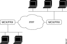
PPP is a protocol used for multiplexed LAN transport over a point-to-point link.
IN V12.2, the use of this protocol is possible over a synchronous line.
PPP consists of main components:
The LAN protocols that are supported are IP, IPX, CNLP and the bridge mode.
The supported LCP options are MRU (Maximum-Receive-Unit) and Magic-Number.
The MRU option specifies the maximum size of the information transported, in bytes, in the PPP packet received by the local equipment.
The Magic-Number option is a method of detecting loops on the link either in the negotiation phase or in the traffic phase. Its implementing triggers the periodic transmission of LCP maintenance messages in the traffic phase.
When a physical line switches into service, the PPP function starts by activating the LCP protocol which negotiates the global parameters of the link such as the size of the exchanged packets (MRU) or the use of a loop detection mechanism (Magic-Number).
Once the LCP connection has been made, the various configured NCP levels attempt in turn to make a connection with the corresponding remote level.
When an NCP level has been established, the associated LAN information can then circulate over the link.
An LCP or NCP connection can be cut off:
Whatever the reason for the cutoff, the disconnected protocol remains frozen for a configurable period of time. When the freeze period is over, it will make another attempt at connection.
During the freeze period, the protocol in question may be activated by a connection request from the remote end.
To be protected from possible looping during the negotiation phase, an LCP or NCP protocol will consider itself to be out of service if it does not manage to connect after a configurable period of time equal to the freeze period. This timer also protects the terminating phase of a connection.
Once the MRU negotiations are over, these is no further check on the size of the received frames on the PPP line so as to remain compatible with some of the equipment on the market which never negotiates the MRU.
The periodic transmission of the LCP Echo-Request maintenance messages depends on the implementation of the Magic-Number by both sites.
The administrative closing of an NCP at the request of an SNMP manager is not supported.
The PPP function supports the addition, removal or the substitution of a PPP line by the simple selective reinitialization.
The parameters needed for service configuration are as follows:
C1R1 PPP line type = 39
C12Ri PPP line configuration parameters
P0 PPP profile (123)
P28 Line speed
P46 Local subscriber number
P103 to 106 NCP activation
P115 to 119 parameters relative to LCP/NCP protocols
P120 to 121 parameters relative to the Magic-Number option
P122 to 123 parameters relative to the MRU option
 Example
The nodes are IP routers interconnected via a PPP link.
| Node 1 configuration | Comments | Node 2 configuration |
|---|---|---|
C1R1P1 = 39 C1R1P0 = 123 C1R1P46 = 1 C1R1P103 = 1 C1R1P104 = 0 C1R1P105 = 0 C1R1P106 = 0 C1R1P120 = 1 | PPP line type PPP profile Local subscriber number IPCP activation BRDGCP not activated IPXCP not activated CLNPCP not activated Implementation of Magic-Number | C1R1P2 = 39 C1R2P0 = 123 C12R2P46 = 2 C12R2P103 = 1 C12R2P104 = 0 C12R2P105 = 0 C12R2P106 = 0 C12R2P120 = 1
|
C35R0P0 = 1,0,1,0 | Remote VP number on module 0 =0 | C35R0P0 = 1,0,1,0 |
C36R0P0 = 900010001 | X121 address of target point (Note 1) | C36R0P0 = 900020002 |
C36R2P0 = 0 | VP No. associated with target point | C36R2P0 = 0 |
C36R3P0 = 1,0,0 | Connection characteristics (Note 2) | C36R3P0 = 1,0,0 |
C36R3P0 = 1,250,1 | silence timer = 2500s, call retransmission timer = 10 s | C36R4P0 = 1,250,1 |
C41R1P0 = 0 | VP No. (same as C36R2P0) | C41R1P0 = 0 |
C41R2P0 = 194,107,114,1 | Local IP address associated with VP | C41R2P0 = 194,107,114,1 |
C42R0P0 = 194,107,114,2 C42R1P0 = 90001001 | Distant IP address X121 address of target point | C42R0P0 = 194,107,114,1 C42R1P0 = 90002002 |
![]()
![]()
![]()
![]()
![]()
![]()
![]()
![]()
Posted: Thu Jan 25 13:58:58 PST 2001
All contents are Copyright © 1992--2001 Cisco Systems, Inc. All rights reserved.
Important Notices and Privacy Statement.