|
|

Frame relay (FR) is a frame mode transfer service for long distance communication WAN (Wide Area Network).
The frame relay is part of the fast frame switching technologies.
It multiplexes data at level 2 (ISO layer modeling link layer) without resuming transmission on errors.
To do this, it is different from the X.25 protocol and brings to the benefit of applications progress made with data transmission networks making level 2 error detection processing and transmission recovery on detected errors pointless.
It is simplified with respect to the X.25 protocol; the frame relay protocol offers shorter switch crossing times and faster bit rates.
The service is based on the modified LAP-D (LAP-D : Link Access Procedure on D-channel) frame structure, designated as LAP-F (defined by IUT-T recommendation Q.922).
Like X.25, the frame relay offers services in the connected mode.
The existence of a logical end to end location requires the prior permanent connection (PVC : Permanent Virtual Connection) with associated signaling (LMI or Local Management Interface, defined in IUT-T recommendation Q.933 Appendix A and standard ANSI T1.617 Appendix D).
The frame relay technology applies to WAN networks and various interworking standards with all the protocols that exist make this a multiprotocol transport service ideal for establishing intersite WANs (interworking with X.25, SNA, Apple Talk, IP, IPX, DECNET).
The performance of the frame relay also makes it possible to transport voice and images, whether correlated or not, with data originating from LANs.
There are two types of frames:

DLCI = Data Link Connection Identifier Destination identifier address field
DE = Discard Eligibility bit Marks a frame as eligible for deletion in case of congestion
BECN = Backward Explicit Congestion Notification bit Transmission upstream of congestion difficulty
FECN = Forward Explicit Congestion Notification bit Transmission downstream of congestion problem detection
C/R = Command/Response indication bit This bit is not used at frame relay level. It is used at higher level protocols.
msb = Most Significant Byte
lsb = Least Significant Byte
LMI signaling can be of three types:
Three major interfaces have been defined by the Frame Relay Forum.
UNI (User to Network Interface)
NNI (Network to Network Interface) (not supported by V12.2).
NUI (Network to User Interface).
The subscriber LMI (LMI UNI) regularly transmits status inquiry messages and the network LMI (LMI NUI) answers with status report messages.
LMI UNI signaling enables subscribers to find out about the PVC status of the network, thus inhibiting the use of an unavailable PVC and supplies procedures for detecting and modifying the following events:
Two standard protocols are used for the local management interface:
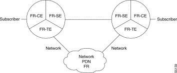
FR-TE = Network access
FR-CE = Subscriber access
Supported protocols: FR-CE and FR-TE interfaces can be transparent or manage encapsulation corresponding to the higher transported level protocol.
FRA (or FRAV) : FR subscriber connecting to an X.25 network.
FRSNA : Transport of SNA flow as per RFC 1490
FRIP : Transport of LAN adaptation protocol as per RFC 1490.
FRT : No processing performed
FRI : Reliable transport on frame relay
FRSW : Specific case of FRI where relay operation is simplified. This interface is used more particularly for connection of voice boards.
FRAV: Automatic recognition of transported protocol type and selection of one of the above modes.
The traffic profile associated with a Frame Relay connection is defined by a set of parameters.
CIR (Committed Information Rate) Corresponds to the maximum average rate per connection (PVC) for a period T.
Bc (Committed burst) Maximum duration a connection may use to transmit one or several frames consecutively.
Be (Extended Burst) Additional tolerance on the value of Bc.
CIR = 0 : The network does not guarantee data transfer.
Positioning of the DE bit of the frames which may lead to elimination of frames on the following nodes in case of congestion.
Congestion management is based on the control of the bit rate received from the user to the network. Management is shared between end equipment and network nodes, as follows:
FR-CE interface
FR-TE interface
Stringent checking of the rate received from the user is carried out in the access equipment. This check is performed by DLCI. The possible rate checking strategies are:
S1 = Control: "traffic policing (discard but don't delay)" Standardized management of CIR. The received frame transit time is privileged. In case of congestion, access frames are discarded.
S3 = Smoothing: "traffic shaping (delay but don't discard )" Optimized congestion management, limits frame loss. Outside congestion, traffic is smoothed on Bc+Be to minimize frame loss risks. On network congestion indication, FRAD (access equipment) privileges transit time by discarding excess frames (> Bc).
S4 = Permanent smoothing: "traffic shaping (delay and discard only if no more memory)" Optimized congestion management to minimize frame loss. The traffic is always smoothed. Outside of congestion, it is smoothed on Bc+Be, as in previous case. On network congestion indication, the FRAD continues to smooth but on Bc.
Table 13-1 summarizes the strategies and location of the flow control.
| Strategies | Definition of control strategy | Control location | Recommendation |
|---|---|---|---|
S1 | CIR control user to network direction | CE,TE | FR User |
S3 | smoothing during transmission outside of congestion | TE | FR User |
S4 | permanent transmission smoothing in user to network direction | TE | Non-FR User |
 Example
There are two cases of flow control (CIR):
Network Not Congested
If the network is not congested: As long as the amount of information received is below the Bc credit, frame switching will take place transparently in real time. When the amount of information received without a bit DE set to 1 exceeds the Bc credit and is less than the Bc+Be credit, the frame is switched in real time with discard priority information (bit DE set).
For the control strategy (S1):
When the authorized Be credit is exceeded, all the frames with bit DE = 1 are discarded. defined. When the amount of information received exceeds the Bc+Be credit, all the received frames are discarded.
For strategies S3 and S4 : defined. When the amount of information received exceeds the Bc+Be credit, received frame switching is suspended. Frame switching is resumed as soon as the rate drops between Bc+Be.
| Rate Strategy | DE=1, d< Be | DE=0 Bc<d<Bc+Be | DE= d>Be | DE=1 or 0 d>Bc+Be |
|---|---|---|---|---|
S1 | S | SDE | R | R |
S3 | S | SDE | SLBe | SLBe |
S4 | S | SDE | SLBe | SLBe |
R = frame "discarded"
S = frame "switched" in real time
SDE = frame "switched" in real time. The DE bit is set to 1
SLBe = frame transmitted with smoothing on Bc+Be
On reception of a set BECN,
For strategies 1 and 3: All the received frames are discarded.
For strategy 4 : The traffic at CIR is reduced and received frame switching is suspended. It is resumed as soon as the rate drops below Bc. If the network is still congested in spite of smoothing (more than 50% received frames containing BECN bit during smoothing time interval), traffic is reduced with a drop to 1/8th of the current CIR up to the minimum CIR. If the congestion decreases (less than 50% frames received containing bit BECN during the smoothing time interval), the traffic is smoothed to 9/8th of the current CIR up to the configured CIR.
The network is considered to be no longer congested when all the frames received from the network no longer have a BECN bit for a given time interval (ª 200 ms by default).
| Rate Strategy | DE=0, d < Bc | DE=1 d > Bc | DE=1 or 0 d > Bc |
|---|---|---|---|
S1 | S | R | R |
S3 | S | R | R |
S4 | S | S | SLBc |
SLBc = frame transmitted with smoothing on Bc
Congestion control in an FR network takes place generally on trunk lines by managing the filling rate of the frames in the transmission queues.
When the congestion thresholds of these queues are reached, the defense mechanisms are implemented that are graduated according to the COS (Class Of Service, see below). A first defense level consists in setting the FECN and BECN bits for the congested DLCIs.
Management in this way relieves congestion for the user by reducing the flow of data to be switched in the network. It is aimed at establishing a stable slaving loop between user and network.
To offer a slaving loop to all types of traffic, including unidirectional traffic like file transfers, the distant end equipment receiving the FECN frame notified by the network may return spontaneously to the transmitter a specific slaving frame containing the BECN bit = 1 and bit DE=0.
Slaving frames are generated and processed at the FRTE interface of the end equipment as a function of a configuration parameter (par 73).
Each FR connection belongs to one of the following flow types:
To offer a fair share of the physical line passband between UBR, VBR and VBR-TR users, 2 transmission queues are implemented per trunk line (1 queue per COS).
Priority FA (VBR-TR) : a safeguard threshold limited to 512 elements. In practice, this FA only contains n elements (a few dozens). This number n corresponds to the voice frames awaiting transmission i.e., at most, the number of n connections multiplexed on the physical line.
Non-priority FA (VBR/UBR) : 4 thresholds are defined, threshold1, threshold2, threshold3 and threshold4.
A Frame Relay network is a way of interconnecting FR users as well as users dialoguing with any protocols.
On access, FR users are connected to the network solely by PVC FRs whereas Legacy protocol users are connected to the network with PVCs or SVCs (e.g. X25). Any data transfer on a PVC FR is only possible once a connection has been established.
In the case of a PVC connection (FR, SDLC, LAN) to a PVC FR, connection is internal to the equipment (between input and output). This connection is established at the initiative of one of the calling ends. The calling end must indicate the address of the other connection end (the called end). Each connection end is associated with an address that can be deduced from the configuration (implicit) or indicated specifically as a configuration (explicit). It is advisable for the calling end to be the line connected to the subscriber (FR_CE type), with the other end on the network line (FR_TE type).
Example : Simple switching of transparent FRAV frame
Case of PVC-PVC connection attached to FR
To connect between DLCI1 and DLCI2, the address of DLC12 is associated with DLCI1. DLCI1 is the calling end and DLCI2 is the called end.
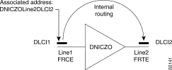 Example
The information needed for configuring a DLCI is:
Each attached DLCI is associated with a virtual line (VL) number (used by routing).

The attached DLCI type is configured in class 30 and the DCL2 is configured in class 32.
The attached DLCIs can be configured at the user or network end as follows:
C32R0 : physical_line, (empty=FF), DLCI, [cos/priority]
R1 : [num_lv], [establishing_mode], (empty=FF), rec_c30
R2 : [CIR], [Bc], [Be], [CIR_min], [strategy]
R3 : [distant_address]

The principle here again is that of positioning the QOS of a DLCI (CIR, strategy etc.) on the user end. The exceptions are when the user is a Protocol P that is not FR (X25, FRAD, ...) and wishes to go out over a public FR network (DTE) or when the DLCI is of the FRI type). In this case, the QOS is configured on the network end.
The interpretation of the configured values of CIR, CIR_min, Bc, Be and strategy is connected to the value assigned to the COS (Class Of Service) field.
* COS VBR-TR (1)
The other CIR, CIR_min, Bc,Be, strategy parameters are not significant. However, if these parameters are configured, the values must belong to the authorized range. Other wise, the DLCI is not initialized.
* cos VBR (0)
If the CIR is not configured, the DLCI will be activated without congestion management.
If the values of the CIR,CIR min,Bc,Be parameters are not included between 1 and 47, the DLCI will not be taken into consideration (EVR (significant event) config error). Depending on the CIR, Bc must be in a range of values. These values are described in Table 13-4. If the Bc is outside the range, it will be set to the value closet to the authorized range. Therefore, we have Bc < range => Bc= Bc min, Bc > range => Bc=Bc max. The CIR min must be less than the CIR, otherwise, CIR min = CIR.
When the CIR_min, Bc, Be, strategy parameters are absent, they are deduced from the rules: CIR_min=Bc=CIR; Be=2 * CIR. The default strategy is checking except as concerns the protocol FRI, for which the strategy is set during smoothing.
* cos UBR (2)
If the CIR is not configured, it is assimilated to a null CIR. All the other CIR values will be refused (EVR (significant event) configuration error). The CIR min and Bc parameters will not be significant. If Be is not configured then it will be at Be= U% line. The default strategy is that of checking except for the FRI protocol for which the strategy is forced on smoothing.
* cos not configured
By default, cos equals the value VBR.
| CIR or CIR min | Bcmin | Bcmax | Page Bc |
|---|---|---|---|
0 | 0 | 0 |
|
1.2 | 2.4 | 4.8 | 0.6, 1.2, 2.4, 4.8 |
2.4 | 1.2 | 9.6 | 1.2, 2.4, 4.8, 9.6 |
4.8 | 2.4 | 19.2 | 2.4, 4.8, 9.6, 14.4, 19.2 |
9.6 | 4.8 | 38.4 | 4.8, 9.6, 14.4, 19.2, 32, 38.4 |
14.4 | 7.2 | 57.6 | 9.6, 14.4, 19.2, 32, 38.4, 48, 56 |
19.2 | 9.6 | 76.8 | 9.6, 14.4, 19.2, 32, 38.4, 48, 56, 64, 72 |
32 | 16 | 128 | 19.2, 32, 38.4, 48, 56, 64, 72, 96, 128 |
38.4 | 19.2 | 153.6 | 19.2, 32, 38.4, 48, 56, 64, 72, 96, 128, 144 |
48 | 24 | 192 | 32, 38.4, 48, 56, 64, 72, 96, 128, 144, 192 |
56 | 28 | 224 | 32, 38.4, 48, 56, 64, 72, 96, 128, 144, 192 |
64 | 32 | 256 | 32, 38.4, 48, 56, 64, 72, 96, 128, 144, 192, 256 |
72 | 36 | 288 | 38.4, 48, 56, 64, 72, 96, 128, 144, 192, 256 |
96 | 48 | 384 | 48, 56, 64, 72, 96, 128, 144, 192 to 384 in steps of 64 |
128 | 64 | 512 | 64, 72, 96, 128, 144, 192 to 512 in steps of 64 |
144 | 72 | 576 | 72, 96, 128, 144, 192 to 576 in steps of 64 |
192 | 96 | 768 | 96, 128, 144, 192 to 768 in steps of 64 |
256 | 128 | 1024 | 128, 144, 192 to 1024 in steps of 64 |
320 | 160 | 1280 | 192 to 1028 in steps of 64 |
384 | 192 | 1536 | 192 to 1536 in steps of 64 |
448 | 224 | 1792 | 256 to 1792 in steps of 64 |
512 | 256 | 2048 | 256 to 2048 in steps of 64 |
576 | 288 | 2304 | 320 to 2048 in steps of 64 |
640 | 320 | 2560 | 320 to 2048 in steps of 64 |
704 | 352 | 2816 | 384 to 2048 in steps of 64 |
768 | 384 | 3072 | 384 to 2048 in steps of 64 |
832 | 416 | 3328 | 448 to 2048 in steps of 64 |
896 | 448 | 3584 | 448 to 2048 in steps of 64 |
960 | 480 | 3840 | 512 to 2048 in steps of 64 |
1024 | 512 | 4096 | 512 to 2048 in steps of 64 |
1088 | 544 | 4352 | 576 to 2048 in steps of 64 |
1152 | 576 | 4608 | 576 to 2048 in steps of 64 |
1216 | 608 | 4864 | 640 to 2048 in steps of 64 |
1280 | 640 | 5120 | 640 to 2048 in steps of 64 |
1344 | 672 | 5376 | 704 to 2048 in steps of 64 |
1408 | 704 | 5632 | 704 to 2048 in steps of 64 |
1472 | 736 | 5888 | 768 to 2048 in steps of 64 |
1536 | 768 | 6144 | 768 to 2048 in steps of 64 |
1600 | 800 | 6400 | 832 to 2048 in steps of 64 |
1664 | 832 | 6656 | 832 to 2048 in steps of 64 |
1728 | 864 | 6912 | 896 to 2048 in steps of 64 |
1792 | 896 | 7168 | 896 to 2048 in steps of 64 |
1856 | 928 | 7424 | 960 to 2048 in steps of 64 |
1920 | 960 | 7680 | 960 to 2048 in steps of 64 |
1984 | 992 | 7936 | 1024 to 2048 in steps of 64 |
2048 | 1024 | 8192 | 1024 to 2048 in steps of 64 |
The establishing mode of an FRAV (C32R1) station can take on different values which determine a more or less complex behavior in association with the DLCI :
* calling type (value 0)
* called type (value 1)
As soon as the virtual line is switched on (or the DLCI becomes available if the LMI is configured on the FR line) the station stands by to receive a call from the distant end and checks the caller address.
* mixed type (value 2)
Same behavior as for the calling type but enabling call collisions that is "recovers" by means of a random value call-back time-out.
* datagram type (value 3)
On reception of the first datagram after the virtual line is switched on (or the DLCI becomes available if the LMI is configured on the FR line), a call is emitted to the distant end. The first datagram received and the others that arrive during the setting up of the support CV are stored in an internal queue capable of holding up to datagrams. Beyond that, the datagrams are trashed and a loss EVR (significant event) is generated.
If a call is received from the distant end before the first datagram is received, it is processed in the same way as on the mixed type stations.
This mode can be used when the FR connection passes through a switched network. This can be a packet switching network (X25) or a circuit switching one (ISDN). This mode is capable of liberating the resources of this type of network in the absence of traffic.

* called without caller check type (value 4)
Type defined for TRANSPAC behaving like the called type except for the check of the caller address check which is not carried out.
It should be noted that a DLCI FRAV of this type offers the same functionality as the DLCI of an LV FRT.
* called type dynamically managing RFC1356 (value 6 - FRIP);
On reception of a call, the User Call Data (DAU) is analyzed. If it contains a valid RFC1356, encapsulation/decapsulation of the corresponding RFC1490 will b e implemented on all the datagrams.
If the DAU does not contain an RFC1356, the datagrams will be managed transparently.
Note that a DLCI of this type offers the same functionality as the DLCI of a virtual line LV FRIP.
* datagram type managing NULL-Encapsulation (value 5)
If the support CV has not already been established when the first datagram is received, it will be analyzed to check that it conforms to RFC1490 (byte 03). The emitted call DAU is then set to 00 (NULL encapsulation) and the null encapsulation is applied to all the datagrams.
If the datagram is not compliant with RFC1490 it will be managed transparently (empty DAU).
If a call is received before the first datagram is received, management will be as in the case of a "called with RFC" situation.
* datagram type dynamically managing RFC1490 (value 7)
If the support CV has not already been established when the first datagram is received, it will be analyzed to identify its RFC1490. The emitted call DAU then contains the corresponding RFC1356 and the appropriate encapsulation /decapsulation is applied to all the datagrams. If the datagram is not compliant with RFC1490 it will be managed transparently. If a call is received before the first datagram, management will be the same as for the "called with RFC".
For the connections based on DLCIs with a protocol in the SVC mode with multiplexing (in particular X25), there is no internal connection. Data transfer on this type of PVC takes place after the setup of an end to end connection between subscribers ( CV X25 for instance). However, this type of DLCI can be compared to a DLCI of the called type. If routing is on the physical line, it will be necessary to associate it with a called party address for this DLCI. This address must contain all the subscribers that can be connected through this PVC.
Example of X25 connection to a Frame Relay access:
Case where the virtual line is not assigned to the DLCI.
In the node Z0 configuration, the DLCI used for reaching subscribers to node Z1, will be referenced with address DNICZ1. The calls will first be routed over the physical line. Locally with respect to the line, the DLCI is chosen by comparison between the received called address and the address associated with the DLCI by configuration
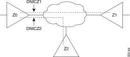
Class 9
Z1 -> line2
Z2 -> line2
 Example of PVC-attached PVC:
* FR_CE end (user)
C32R0 / 0 : 1,,901,0 cos VBR (0) on the DLCI 901 of line 1
R1 / 0 : ,,,1 LV of dynamic number described in C30R1 (Pr 83)
R2 / 0 : 6,,,,1 CIR called party = 6 (9600 bit/s); strategy = control
R3 / 0 : 900000020902 address to call to reach network DLCI
(sub-address = 0902 = DLCI output)

C30R1 : 0,83 FRAV profile (without deltas)
* FR_TE end (network)
C32R0 / 1 : 2,,902 DLCI 902 of line 2
R1 / 1 : ,,,1 LV of dynamic number described in C30R1
R2 / 1 : DLCI of called type without check by default
R3 / 1 : QOS expressed at user end (default values =FF)
The backup configuration can be obtained with or without the use of the notion of a virtual line.
Example of backup without the use of a virtual line.
In this case, the DLCI3 must be identified as a backup of DLCI2. To do so, DLCI3 is declared to be of the called type without checking and using as associated address: DNICZOLine2DLCI2 .
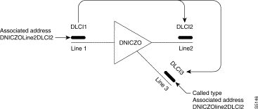 Example of Back-Up Without the Use of a Virtual Line
| Class 32 | DLCI1 DLCI2 |
|---|---|
rec 0, parameter i : line1, ,DLCI1,priority | rec 0, parameter j : Line2 , ,DLCI2,priority |
rec1, : ,0(calling), ,ind30n | rec1, : , 4, ,ind30m |
rec2 | rec2 |
rec3 : DNICZOLine2 DLCI2 | rec3 : |
DLCI3 backup |
rec 0, parameter k : line2, ,DLCI3,priority |
rec1, : ,4 (called without check), ,ind30i |
rec2 |
rec3 : DNICZOLine2 DLCI2 |
The ISDN accesses support the PVC Frame Relay on channels B. ISDN can be used as a backup or as direct access to for the FR access points except for switch connections for PVC-PVC. The DLCI activated on channels B will depend on the ISDN address of the distant end. In the definition of the PVC FR, it is therefore necessary to associate an ISDN address with them through a class 22 index. On the establishing of a channel B. all the DLCIs with an associated ISDN corresponding to the ISDN address of the distant equipment will be activated.
Access to a DLCI on channels B, cannot be accomplished via the virtual line concept. Routing will be solely on channel D or in conjunction with the overflow backup function (GDL).
The behavior of the LMI on ISDN is optimized to shorted the DLCI availability detection time. The last polling is performed after one second. The following are carried out in accordance with T391. It is highly advisable to use the RAPID mode to detect the availability of the LMI DCLIs.
The backup service is offered for cases A and B.
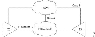 Back-Up Service is Offered for Cases A and B
An emergency shutdown is possible using GDL when the line or the comes back into service. In the case of a PVC emergency shutdown, it is necessary to assign a virtual line to each PVC to be backed-up (see the example below).
There are two channel B cutoff modes. Either cutoff on 0 CV, or cutoff due to traffic absence. The choice of behavior is made in class 12 associated with channel D (P60 or P76), but cutoff is still effective in the case of a backup or when the backed up subscribers are of the "datagram" type in that the necessary internal connection between the subscriber and the Frame Relay output is only requested on data reception. In addition, in the event of LMI being used, the polling frequency must be at least twice the inactivity surveillance period.
Backup is on line or when the PVC is out of service. In both cases, all the DLCIs provided for on the ISDN are set up systematically.
If the backed-up PVC has the same properties when it is backed up on ISDN (same DLCI number and same protocol), a single DLCI declaration will suffice. Otherwise it will be necessary to configure the DLCI of the normal line and the backup DLCI on ISDN.
Examples case of connection to an FR network offering a backup service on ISDN
1/ One DLCI for the normal line and one for the backup line.
Declaration of DLCI2 on line2, backup by ISDN with the address NUMRNIS. The ISDN access is located on line3. The backup on ISDN uses the same DLCI number and the same properties (FRAV- transparent).
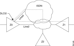 Example
parameter line2 : 19 (line type = FR)
parameter line0 : 14 (line type = channel D)
parameter line1 : 15 (line type = channel B)
rec line 2 : Profiles 84 or 85 (FRTE/FRCE)
rec line 3: Profile 47 (ISDN)
rec 0, parameter i : line2,ind22,DLCI2,cos
rec1, : , , ,ind30i
rec2
rec3
rec0, parameter ind22
rec1, parameter ind22 : NUMRNIS
rec2, parameter ind22: 70(incoming and outgoing call), ind30j , 19 (line type =FR)
rec ind30i: profile 83 (FRAV)
rec ind30j: Profiles 84 or 85 (FRTE/FRCE)
AB = line2 -> 4 (1+nbackup),2,0,line2,line0
2/ Two different DLCIs for the normal line and for the backup line DLCI 2 is backed up by DLCI3 on the ISDN access. Under these conditions two DLCIs must be defined. With respect to the previous example, The following configuration elements are changed:
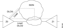 Configuration
DLCI2: no reference to ISDN
rec 0, parameter i : line2, ,DLCI2,priority
rec1, : , , ,ind30i
rec2
rec3
DLCI0: line number not to be specified. However, DLCI0 must be identified as backup of DLCI2, hence the associated address of recurrence 3..
rec 0, parameter j : ,ind22,DLCI0, priority
rec1, : ,01(called type) , ,ind30i
rec2 rec3 : DNICZOLine2DLCI2
rec0, parameter 22,
rec1, parameter ind22 : NUMRNIS
rec2, parameter ind 22: 70 (incoming and outgoing call), ind30j , 19 (line type =FR)
rec ind30i: profile 83 (FRAV)
rec ind30j: Profiles 84 or 85 (FRTE/FRCE)
3) Emergency line shutdown
The following elements must be added to the previous examples:
rec line2 P129 : ind22 P130 : 1 (emergency shutdown)
AB= line2 -> 4(1+nbackup),3,0,line2,49 (GDL),line0
DLCI 2 and 0 of line 2 are backed up by ISDN. The backing up of DLCI2 uses the ISDN1 address and the backup of DLCI3 uses the ISDN2 address. To shut down the backup, assign a virtual line to each of these DLCIs. The DCLIs on the backed up line must be configured with shutdown of the backup and the DLCIs on ISDN without shutdown of the backup. It is necessary to declare the DLCIs on the backed up line and on the backup line because they do not have exactly the same properties.
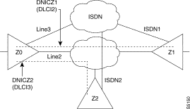 Example
parameter line2 : 19 (line type = FR)
parameter line0 : 14 (line type = channel D)
parameter line1 : 15 (line type = channel B)
rec line 2 : Profiles 84 or 85 (FRTE/FRCE)
rec line 3: Profile 47 (ISDN)
rec 0, parameter i : line2,,DLCI2,cos ec1, : LP1, , ,ind30i rec3 : DNICZ1 DLCI on line3 (ISDN) rec 0, parameter k: ,ind22k,DLCI2,prio ec1 : , , ,ind30k rec3 : DNICZ1 | rrec 0 parameter j : line2,,DLCI3,cos ec1 :LV2 , , ,ind30j rec3 : DNICZ2
rec 0 parameter l : ,ind22l,DLCI3,prio rec1, : , , ,ind30k rec3 : DNICZ2 |
(protocol on DLCIs)
rec ind30i Par 0 =86 (profile fri) Par 129= ind22k Par 130= 1 (backup off)
recind30j Par 0= 86 (profil fri) Par 129= ind22l Par 130= 1 (backup off)
recind30k Par 0= 86 (profile fri)
(correspondence X25/RNIS,RTC)
rec0 Par ind22k DNICZ1 Par ind22l DNICZ2
rec1 Par ind22k RNIS1 Par ind22l RNIS2
rec2 Par ind22k 70,ind30k,19 Par ind22l 70,ind30k,19
(routing) Z1 -> 4,3,0,LP1,49 (gdl), line0 (rnis)
The following diagram gives the steps in the configuration process of a pair of transit frame relay types using the standard profiles.
Many additional parameters can be configured according to specific needs of the user. Details of the parameters are described in chapter 8.
Reminders:
| Speed | Max Packet size in bytes |
|---|---|
600 bit/s |
|
1200 bit/s |
|
2400 bit/s |
|
9600 bit/s |
|
14,4 kbit.s |
|
19,2 kbit.s |
|
38,4 kbit.s |
|
48 kbit.s | 128 |
56 kbit.s | 128 |
64 kbit.s | 128 |
72 kbit.s | 256 |
128 kbit.s | 512 |
144 kbit.s | 512 |
256 kbit.s | 1024 |
512 kbit.s | 2048 |
1 Mbit.s | 4096 |
2 Mbit.s | 4096 |
Absence of negotiation
Packet size
Parameter 61 = 0 class 30
Packet size
Parameters 62 and 63 class 30
This table is dimensioned for 32 byte voice frames every 20 ms with one voice channel.
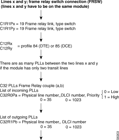 Configuration
The following diagram gives the steps in the configuration process of an HDLC or frame relay subscriber interface using the standard profiles.
Additional parameters can be configured according to specific needs of the user.
Details of the parameters are described in chapter 8.
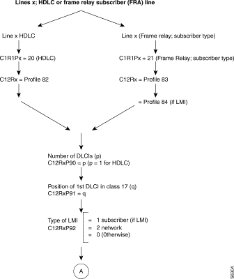 Configuration
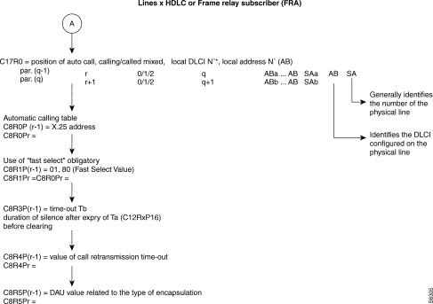 Line x HDLC or Frame Relay Subscriber (FRA)
As these PVCs have no implicit physical output port, at least one frame relay line in class 1, recurrence 1 must be configured "19" (frame relay) enabling the routing tables to be configured in class 32.
The frame relay physical lines have an 84 profile (FR_TE) or 85 profile (FR_CE) defined in class 12.
In class 30, the connection parameters of each PLL are defined by means of profiles (see available profiles).
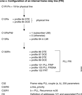 Configuration
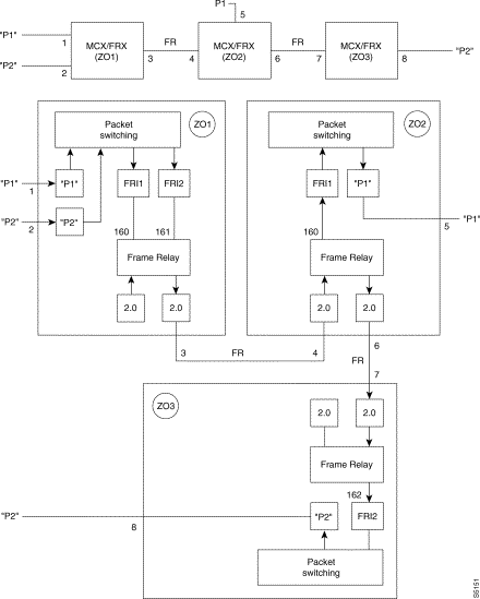 Diagram
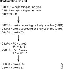 Configuration
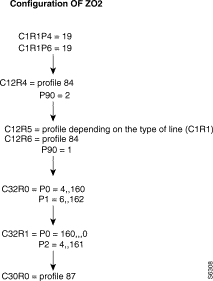 Configuration
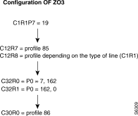 Configuration
Example of FNA/FRA Configuration
 Example
P4 = 21 
line 4 = FRA
P0 = 83 
FRA profile
P1 = 90,2 
2 DLCIs (101 and 88)
P2 = 91,10 
rest of description in C17R0 row 10
P3 = 92,2 
LMI of NUI (Network to user) type and still of network type
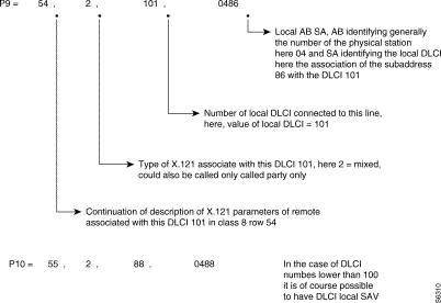 C17R0
C17R0
This local (AB SA) is used to format the address of the called in the call packet as follows:

 Diagram
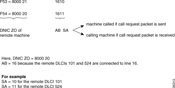 C8R0
C8R0
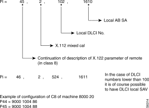 C17R0
C17R0
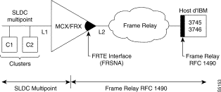
1. Line L1: (See SNA/SDLC configuration in chapter 3.5.1).
2. Line L2: C1R1L2 = 19 frame relay
C1R12R2 = Profile 84 or 85
C32R0 po = 2,,1,
C32R1 po = 160,,,0
C30R0 = Profile 120
Frame relay subscriber using FRI for encapsulation.
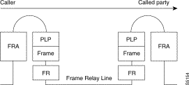 Frame Relay Subscriber using FRI for Encapsulation
FR (2) | Frame (2) | Packet (3) | SEP (FRA) | DATA | CRC |
The SEP field of the multiframe protocol is negotiated between FRA. It is thus optional.
Any subscriber using FRI for encapsulation.
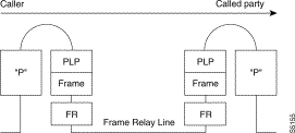 Any Subscriber using FRI for Encapsulation
FR (2) | Frame (2) | Packet (3) | DATA | CRC |
REMARKS
Frame relay subscriber using FRT.
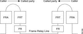 Frame Relay Subscriber using FRT
FR (2) | SEP (FRA) | DATA | CRC |
Any subscriber using FRT
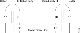 Any Subscriber using FRT
FR (2) | DATA | CRC |
SDLC subscriber using FRSNA
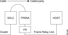
FR (2) | LLC2 | QLLC | DATA | CRC |
X.25 subscriber using FRSNA (MPSI)

FR (2) | LLC2 | QLLC | DATA | CRC |
LAN subscriber using FRIP.
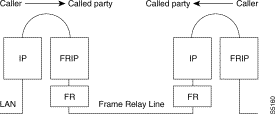
FR (2) | RFC1490 | DATA | CRC |
REMARKS
 .
.
Example of routing table for PVC linking switch ZO = 00 with ZO = 01.
Routing table of switch 00:
Routing table of switch 01:
When several PLLs use different protocols, it is recommended that these internal VCs be routed by using different ZOs (one ZO per PVC) or routing at the level of the AB.
![]()
![]()
![]()
![]()
![]()
![]()
![]()
![]()
Posted: Thu Jan 25 14:01:51 PST 2001
All contents are Copyright © 1992--2001 Cisco Systems, Inc. All rights reserved.
Important Notices and Privacy Statement.