|
|

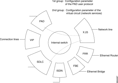
For each terminal connected to a line of the FastPad there are, whatever protocol is used, two groups of parameters to configure:
Group 1: | Parameters defining the choice and the decision to use a protocol "p" on a certain line (to configure on C1R1P0 to 35). |
| For each user line the additional parameters allow to configure the functional options offered. |
Group 2: | Parameters defining the X.25 Interface of the user line facing the X.25 node, represented by the internal switch of the FastPad. This switch manages the virtual circuit between the network line and the user line. |
| These are the network parameters of level (OSI) 3 of the X.25 recommendation. |
With this organization, all network services can be offered to each line, independent of their protocol.

These parameters define the operation mode of the following levels:
These parameters define the level 3 interface facing the internal switch. The following parameters are distinguished:
Example: CUG, throughput class, reversed charging...
Example: Packet length, window size...
They are put together for all protocols in Cl2Rx and the following classes, as a function of the protocol.
X.25 | C12 | X.25 parameters |
Asynchronous | C7 | Abbreviated calling table |
| C8 | Automatic calling table |
| C13 | Parameter X.3 |
X.25 PVC | C17 | PVC table |
| C8 | Automatic calling table |
X.25 PSTN | C13 | Extension parameters |
| C20 | Modem initialization table |
| C21 | XID frame table |
| C22 | X.25/PSTN conversion table |
SDLC | C8 | Automatic calling table |
| C19 | Clusters |
VIP | C8 | Automatic calling table |
| C13 | Station address |
| C19 | Controllers |
BSC 2780/3780 | C8 | Automatic calling table |
| C13 | Station address |
| C19 | Terminal description |
BSC 3270 | C8 | Automatic calling table |
| C13 | Station Address |
| C19 | Controller description |
HDLC and Frame-Relay | C8 | Automatic calling table |
Frame-Relay (subscriber) (FRA)/FRCE | C17 | DLCI table |
Frame-Relay/FRTE,FRSE | C32 | Frame relay PLL couple |
Transit type | C30 | Dynamic X.25 parameters on network FR or B or D channels. |
Network (FRTE) | C30 | Dynamic X.25 parameters on network FR or B or D channels. |
D channel (ISDN) | C22 | X.121-PSTN/ISDN conversion table |
B channels (ISDN) | C30 | Dynamic X.25 parameters on network FR or B or D channels. |
PLL in D channel (ISDN) | C13 | PLL/TEI/profile number relations (defined In C30). |
| C30 | Dynamic X.25 parameters on network FR or B or D channels. |
| C22 | X.121-PSTN/ISDN conversion table. |
MLP | C25 | MLP bundle |
Virtual IP router | C24 | Parameters of IP router connection |
Connection | C17 | LLC table |
| C8 | Automatic calling table |
SNMP, IP Routing | C31 | SNMP and IP router |
They are put together in C12Rx for each protocol and in C18 when a CUG has been allocated to the X.25 call. See Connection Profiles and Parameters chapter of this manual.
To facilitate the operations, the operator has a number of profiles available. A profile is a predefined set of parameters of the groups 1 and 2.
The address fields, present in the call packet. are used to identify the two communicating parties. They are connected to each other when the X.25 virtual circuit is established.
The presence of the fields depends on the type of line. It is configured in C12RxP45:
When one address has been selected the type of address changes with the origin of the call:
The FastPad address format is derived from the network address and it is structured in three hierarchical levels (see "General routing principle" of this chapter).
To adapt the external subscriber format to the internal network format, there is an internal address conversion mechanism; it is available for each line (subscriber and network).
Two tables are available. These tables are configurable for each line and they can be accessed via C9R11 and C9R12.
This conversion takes place according to the value of parameter C12RxP89.
There is an additional feature introduced when the address to convert is not configured in the tables; the call will be refused or the call will be returned in its original format. The choice of the behavior depends on the parameter C12RxP89.
Table C9R11P0 to P199 adapts the external address to the internal address.
The different possibilities are:
Table C9R12P0 to P199 adapts the internal addressing to the external addressing plan.
The different possibilities are here also:
1. Description
2. "Aimed Point" Address
3. Configuration of "Aimed Point"
| · C12R3P89 |
| = | 64 |
|
|
|
|
| Calculation of aimed point. | |
| · C9R11 | PY | = | 567AAAAAA | Initial address + absorption |
|
| Py + 1 |
| 9000 | Calculated address of aimed point |
| · C9RO | Px | = | 9000 | Known DNIC |
| · C9R1 | Px | = | 1, 1, 0, 2 | Routing on 1 line, 1 line, fixed 0 to line 2. |

4. Constraints and Limits
The purpose of this service is to enable a private network composed of several subassemblies, and knowing only the addresses belonging to its own numbering plan, to access a remote subassembly via the "Transpac" network. What is involved is the provision of an end-to-end service between users of a private network via "Transpac." In a transparent manner for the users (in particular as concerns their numbering plan).
A configuration parameter, by line, allows the backup at the input of the switch (or the reproduction at the output of the switch) of the following parameters in an address extension facility:
A second configuration parameter, by line, allows the determination of the behavior to be adopted on the X.25 fields at the input of the switch.
The processing resulting there from may include:
and the possible actions may be:
In practice, to allow access to the intelligent network of Transpac, the functional steps are:
The addresses of the calling party, the called party (and possibly the CUG and RC) are reproduced on any subscriber output line to the private network management.

Addresses a and b are in the private network addressing plan.
Addresses A, B, X, Y are the addresses of the ports.
(0) - | The call-request packet sent on the "private network management" subscriber line has the following form: | |
| @ calling: a | @ called: b |
During the processing of the incoming call, the addresses are modified after backup in the address extension facility
| @ calling: A | @called: | @IR | (Intelligent Network Server address) |
| CUG and RC according to the configuration. | |||
(1) - | The call transmitted to Transpac is the following: | |||
| @ calling: A | @called: | @IR |
|
Address extension:
| @ calling: a | @ called: b |
CUG and RC according to the configuration
(2) - | The call transmittal by Transpac is the following: | |
| @ calling: XA | @ called: B |
Address extension:
| @ calling: XA | @ called: B |
| CUG and RC according to the configuration | |
(3) - | On the "private network management' subscriber line there is a reproduction of the addresses, of the CUG and the RC (according to configuration) | |
| @ calling: a | @ called: b |
Private network management configuration:
By line, two connection parameters are defined:
The values used are:
By default, this parameter is equal to 0 (no processing).
Parameter 111 consequently makes it possible, at the input of the switch, to back up in the "address extension" DTE facility the addresses and even the CUG and RC. This backup takes place before any actions that may be requested by the parameter 112. At the output, this same parameter allows the reproduction of these data from the address extension facility.
Parameter 112 defines the behavior to be adopted. This behavior corresponds to a row in class 26. Class 26 "Table of X.25 field modifications" has only one recurrence and 20 parameters (each parameter has 24 bytes). This parameter is valid only if parameter 111 is different from 0 and is analyzed only on an incoming call.
By default, parameter 112 is equal to 0, which means; no X.25 field to be modified. Value 1 points to parameter 0 in C26 (value 2 to parameter 1 in C26, etc.).
The actions in C26 have the following format:
Type_action, X.25 field, <value> <value>:optional | ||
Type_action: | A | Reserved (e.g. Addition at input of FastPad) |
| B | Addition at output of FastPad |
| C | Change |
| D | Destroy |
| F | Forbid |
X.25 field: | E | called party address |
| A | calling party address |
| F | Facility |
| B, C, D | reserved |
This service allows the checking of the address furnished by the DTE (caller's address at the request of the called party; its called party address upon call confirmation or clearing request) and enables the DTE to use signalling packets having both caller and called party addresses.
For a two-address DTE, the service allows the checking of the caller's address (respectively the called party's address furnished by the DTE during the accepted call or clearing request). If the addresses are not identical, the call is cleared. Otherwise, the call continues normally. The check is carried out in relation to the secondary address if it is configured; otherwise in relation to the main address.
For a single-address DTE, the secondary address (or the main address if the secondary address is not configured) of the DTE is inserted. If the length of the sub-address plus the address to be inserted is more than 15 digits, the call is cleared. This processing replaces the usual address completion processing.
For a non X.25 DTE, the address to DNICZOAB format generated by the FastPad is replaced by the secondary (or main) address.
For a two-address DTE, the main address received is replaced by the secondary address of the DTE (if the latter is configured).
If the length of the secondary address plus the SA is more than 15 digits, the final address is truncated.
For a single-address DTE, the address furnished is eliminated to leave only the SA.
Called party address
In two-address mode:
In single address mode:
In single-address mode.
If the calling address if furnished, the call is freed.
Only the following combinations are managed:
Line 1 of equipment 900240 is a subscriber line with private network addressing. It is configured as 1 address. and subscribes to called party and calling party address transport. The addresses of the outgoing call-request packet from the FastPad must be modified to furnish:
Moreover, the addition of the facility F70100 is desired at the output of FastPad.
The configuration is then as follows:
| Pl11 = | 3 private network management (transport @ calling party and @ called party) |
| Pl12 = | 1 behavior in C26 |
| PO:DACE90402180BFF701000
|
|
In two-address mode:
In single-address mode:
This service is implemented from a connection parameter allowing its activation. This parameter is defined in C12P89. Parameter 89 is already used for address conversions and the Aimed Point. Bit 7 remains available. By default, this bit is equal to 0 and the service is thus not activated. This bit, called "DTE" address presence authorized" is coded as follows: bit 7: DTE address check/insertion (1/0: yes/no).
To check or be able to insert the address furnished by the DTE, C9R11 is used (conversion of address on incoming call). This table can contain 100 addresses. For the same DNICZOAB, a main address and secondary address may exist. In order to identify a secondary address, it is marked with an "E" at the end of the DNICZOAB referring to the secondary address.
The order in which the main and secondary addresses are filled in on the same line in C9R11 is not subject to any constraint. However, it is recommended that the main address be configured first and then the secondary address in order to minimize the travel time of the table during a call from the remote network (in fact, the main address which allows the routing through the use of Aimed Point).
This conversion makes it possible:
Reminder:
Profile 564 is used at the remote network FastPad interface. This profile differs from profile 0 on four parameters:
This functionality is used to present an address other than the main address to any party as a calling address. This address, called the Secondary address, is the one appearing on the invoice.
This service does not use any configuration parameter through DTE access.
When a secondary address is present on a DTE access, this address is stored in C9R11, the letter E being marked at the end of the corresponding DNICZOAB. When the main and secondary addresses are configured. the main address is first filled in on C9R11 (to allow routing) and then the secondary address.
Mode 1: address with Ctrl/insertion parameter = yes
The secondary address S is inserted as calling address if it is present. Otherwise, it is the main address P which is inserted.
Mode 2: addresses with Ctrl/insertion parameter = yes
When the secondary address is filled in, the checking of the caller's address furnished by the DTE covers this secondary address. If the secondary address is not configured, the check is carried out with the main address.
Mode 1: address with Ctr/insertion parameter = yes
The main address is removed from the called address.
Mode 2: addresses with Ctr/insertion parameter = yes
The call transits in the network with its main address to allow routing. If the secondary address is provided for, the call is presented to the DTE with its secondary address (or else with its main address).
It is the secondary address it is provided for (or else the main address) which is inserted by the network (or by the DTE when it is authorized to furnish its address) in the called party address field of a communication packet accepted or on a clearing request in association with the CLAMN service.
The routing available in the FastPad network is a decentralized service and thus managed in each switching node (subscribers node and transit node).
The routing service is activated systematically in each switch. It analyzes the called address of the incoming call packet.
The next step is, by means of decision tables, to deduce the configured routing and the outgoing line number enabling the called party to be reached.
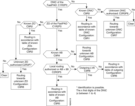
The routing service uses a fixed internal addressing plan which allows the consultation of routing tables. To allow the adaptation of addressing to the DNIC ZO AB format used by the routing service, a certain number of mechanisms may be put in place:
Consecutively, the routing algorithm is executed as follows:
1. Conversion of the called address (if necessary),
2. or aimed point, or intelligent network access, hierarchical analysis of the called address field according to three levels as mentioned in Chapter 4 (configuration).

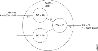
Example: Subscriber A, identified by its address 9000 10 01, establishes a virtual circuit with subscriber B with network address 9000 20 02. The following takes place:

1. Routing activated in the node with ZO = 10:
2. Routing activated in the node with ZO = 20:
During implementation of a new network, the system can take into account additions and withdrawals of subscribers and nodes, without constantly changing the routing tables.
There is another feature available when the called address is not configured in the tables.
There are two configuration possibilities:
This deterministic routing is then reported in the adjacent network element (other switch, terminal).
When it is not possible for the routing to deliver a call the following will happen:
![]()
![]()
![]()
![]()
![]()
![]()
![]()
![]()
Posted: Thu Jan 25 13:57:34 PST 2001
All contents are Copyright © 1992--2001 Cisco Systems, Inc. All rights reserved.
Important Notices and Privacy Statement.