|
|

Table Of Contents
Configuring Phones to Make Basic Calls
Prerequisites for Configuring Phones to Make Basic Calls
Restrictions for Configuring Phones to Make Basic Calls
Information About Configuring Phones to Make Basic Calls
Digit Collection on SIP Phones
Session Transport Protocol for SIP Phones
How to Configure Phones for a PBX System
SCCP: Creating Directory Numbers
SCCP: Assigning Directory Numbers to Phones
SIP: Creating Directory Numbers
SIP: Assigning Directory Numbers to Phones
SIP: Verifying Dial Plan Configuration
SIP: Selecting Session-Transport Protocol for a Phone
SIP: Disabling SIP Proxy Registration for a Directory Number
Configuring Codec for Local Calling Between SIP and SCCP Phones
How to Configure Phones for a Key System
SCCP: Creating Directory Numbers for a Simple Key System
SCCP: Configuring Trunk Lines for a Key System
SCCP: Configuring Individual IP Phones for Key System
How to Configure Cisco ATA, Analog Phone Support, Remote Phones, and Cisco IP Communicator
Troubleshooting Cisco ATA Support
Using Call Pickup and Group Call Pickup with Cisco ATA
SCCP: Configuring Analog Phone Support
SCCP: Verifying Analog Phone Support
SCCP: Configuring Cisco IP Communicator Support
SCCP: Verifying Cisco IP Communicator Support
SCCP: Troubleshooting Cisco IP Communicator Support
Configuration Examples for Making Basic Calls
Configuring SCCP Phones for Making Basic Calls: Example
Configuring SIP Phones for Making Basic Calls: Example
Disabling a Bulk Registration for a SIP Phone: Example
Remote Teleworker Phones: Example
Feature Information for Configuring Phones to Make Basic Calls
Configuring Phones to Make Basic Calls
Last Updated: September 25, 2007This module describes how to configure Cisco Unified IP phones in a Cisco Unified Communications Manager Express (Cisco Unified CME) system so that you can make and receive basic calls.
Note
If you used Cisco Unified Communications Express - QCT to generate a basic telephony configuration, you can skip this module unless you want to modify the configuration to add phones.
Finding Feature Information in This Module
Your Cisco Unified CME version may not support all of the features documented in this module. For a list of the versions in which each feature is supported, see the "Feature Information for Configuring Phones to Make Basic Calls" section.
Contents
•
•
•
•
•
•
•
•
Prerequisites for Configuring Phones to Make Basic Calls
•
•
•
Restrictions for Configuring Phones to Make Basic Calls
•
%DIALPEER_DB-3-ADDPEER_MEM_THRESHOLD: Addition of dial-peers limited by available memory
To configure more dial peers or ephone-dns, increase the DRAM in the system. A moderately complex configuration may exceed the default 256 MB DRAM and require 512 MB DRAM. Note that many factors contribute to memory usage, in addition to the number of dial peers and ephone-dns configured.
Information About Configuring Phones to Make Basic Calls
To configure phones to make basic calls, you should understand the following concepts:
•
•
•
Phones in Cisco Unified CME
An ephone, or "Ethernet phone," for SCCP or a voice-register pool for SIP is the software configuration for a phone in Cisco Unified CME. This phone can be either a Cisco Unified IP phone or an analog phone. Each physical phone in your system must be configured as an ephone or voice-register pool on the Cisco Unified CME router to receive support in the LAN environment. Each phone has a unique tag, or sequence number, to identify it during configuration.
Directory Numbers
A directory number, also known as an ephone-dn for SCCP or a voice-register dn for SIP, is the software configuration in Cisco Unified CME that represents the line connecting a voice channel to a phone. A directory number has one or more extension or telephone numbers associated with it to allow call connections to be made. Generally, a directory number is equivalent to a phone line, but not always. There are several types of directory numbers, which have different characteristics.
Each directory number has a unique dn-tag, or sequence number, to identify it during configuration. Directory numbers are assigned to line buttons on phones during configuration.
One virtual voice port and one or more dial peers are automatically created for each directory number, depending on the configuration for SCCP phones, or for SIP phones, when the phone registers in Cisco Unified CME.
The number of directory numbers that you create corresponds to the number of simultaneous calls that you can have, because each directory number represents a virtual voice port in the router. This means that if you want more than one call to the same number to be answered simultaneously, you need multiple directory numbers with the same destination number pattern.
The directory number is the basic building block of a Cisco Unified CME system. Six different types of directory number can be combined in different ways for different call coverage situations. Each type will help with a particular type of limitation or call-coverage need. For example, if you want to keep the number of directory numbers low and provide service to a large number of people, you might use shared directory numbers. Or if you have a limited quantity of extension numbers that you can use and you need to have a large quantity of simultaneous calls, you might create two or more directory numbers with the same number. The key is knowing how each type of directory number works and its advantages.
Not all types of directory numbers can be configured for all phones or for all protocols. In the remaining information about directory numbers, we have used SCCP in the examples presented but that does not imply exclusivity. The following sections describe the types of directory number in a Cisco Unified CME system:
•
•
•
•
Single-Line
A single-line directory number has the following characteristics:
•
•
•
•
•
Note that you must make the choice to configure each directory number in your system as either dual-line or single-line when you initially create configuration entries. If you need to change from single-line to dual-line later, you must delete the configuration for the directory number, then recreate it.
Figure 7 shows a single-line directory number for an SCCP phone in Cisco Unified CME.
Figure 7 Single-Line Directory Number
Dual-Line
A dual-line directory number has the following characteristics:
•
•
•
•
•
•
•
Note that you must make the choice to configure each directory number in your system as either dual-line or single-line when you initially create configuration entries. If you need to change from single-line to dual-line later, you must delete the configuration for the directory number, then recreate it.
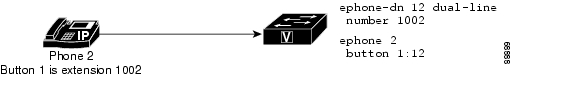
Figure 8 shows a dual-line directory number for an SCCP phone in Cisco Unified CME.
Figure 8 Dual-Line Directory Number
Two Directory Numbers with One Telephone or Extension Number
Two directory numbers with one number have the following characteristics:
•
•
•
•
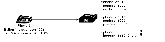
Figure 9 shows a phone with two buttons that have the same number, extension 1003. Each button has a different directory number (button 1 is directory number 13 and button 2 is directory number 14), so each button can make one independent call connection if the directory numbers are single-line and two call connections (for a total of four) if the directory numbers are dual-line.
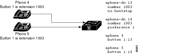
Figure 10 shows two phones that each have a button with the same number. Because the buttons have different directory numbers, the calls that are connected on these buttons are independent of one another. The phone user at phone 4 can make a call on extension 1003, and the phone user on phone 5 can receive a different call on extension 1003 at the same time.
The two directory numbers-with-one-number situation is different than a shared line, which also has two buttons with one number but has only one directory number for both of them. A shared directory number will have the same call connection at all the buttons on which the shared directory number appears. If a call on a shared directory number is answered on one phone and then placed on hold, the call can be retrieved from the second phone on which the shared directory number appears. But when there are two directory numbers with one number, a call connection appears only on the phone and button at which the call is made or received. In the example in Figure 10, if the user at phone 4 makes a call on button 1 and puts it on hold, the call can be retrieved only from phone 4. For more information about shared lines, see the "Shared" section.
The examples in Figure 9 and Figure 10 show how two directory numbers with one number are used to provide a small hunt group capability. In Figure 9, if the directory number on button 1 is busy or does not answer, an incoming call to extension 1003 rolls over to the directory number associated with button 2 because the appropriate related commands are configured. Similarly, if button 1 on phone 4 is busy, an incoming call to 1003 rolls over to button 1 on phone 5.
Figure 9 Two Directory Numbers with One Number on One Phone
Figure 10 Two Directory Numbers with One Number on Two Phones
Dual-Number
A dual-number directory number has the following characteristics:
•
•
•
•
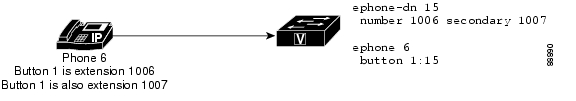
Figure 11 shows a directory number that has two numbers, extension 1006 and extension 1007.
Figure 11 Dual-Number Directory
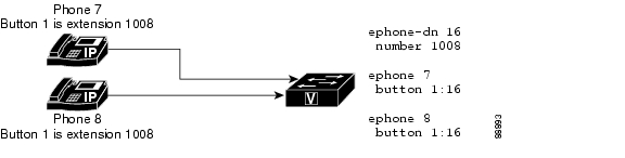
Shared
A shared directory number has the following characteristics:
•
•
•
Because these phones share the same directory number, if the directory number is connected to a call on one phone, that directory number is unavailable for other calls on the second phone. If a call is placed on hold on one phone, it can be retrieved on the second phone. This is like having a single-line phone in your house with multiple extensions. You can answer the call from any phone on which the number appears, and you can pick it up from hold on any phone on which the number appears.
Figure 12 shows a shared directory number on phones that are running SCCP. Extension 1008 appears on both phone 7 and phone 8.
Figure 12 Shared Directory Number
Overlaid
An overlaid directory number has the following characteristics:
•
•
•
•
Overlaid directory numbers provide call coverage similar to shared directory numbers because the same number can appear on more than one phone. The advantage of using two directory numbers in an overlay arrangement rather than as a simple shared line is that a call to the number on one phone does not block the use of the same number on the other phone, as would happen if it were a shared directory number.
For information about configuring call coverage using overlaid ephone-dns, see "Configuring Call-Coverage Features" on page 581.
You can overlay up to 25 lines on a single button. A typical use of overlaid directory numbers would be to create a "10x10" shared line, with ten lines in an overlay set shared by ten phones, resulting in the possibility of ten simultaneous calls to the same number. For configuration information, see the "SCCP: Creating Directory Numbers for a Simple Key System" section
Monitor Mode for Shared Lines
In Cisco CME 3.0 and later versions, Monitor mode for shared lines provides a visible line status indicating whether the line is in-use or not.
When the line is in use, it cannot be used for incoming or outgoing calls. A monitor-line lamp can be off or unlit only when its line is in the idle call state. The idle state occurs before a call is made and after a call is completed. For all other call states, the monitor line lamp is on or lit.
The line button for a monitored line can also be used as a direct-station-select for a call transfer when the monitored line is in an idle state. In this case, the receptionist who transfers a call from a normal line can press the Transfer button and then press the line button of the monitored line, causing the call to be transferred to the phone number of the monitored line.
For configuration information, see the "SCCP: Assigning Directory Numbers to Phones" section.
Monitor mode is intended for use only in the context of shared lines so that a receptionist can visually monitor the in-use status of several users' phone extensions; for example, for Busy Lamp Field (BLF) notification. To monitor all lines on an individual phone so that a receptionist can visually monitor the in-use status of that phone, see the "Watch Mode for Phones" section.
For BLF monitoring of speed-dial buttons and directory call-lists, see "Configuring Presence Service" on page 843.
Watch Mode for Phones
In Cisco Unified CME 4.1 and later versions, a line button that is configured for Watch mode on one phone provides Busy Lamp Field (BLF) notification for all lines on another phone (watched phone) for which the watched directory number is the primary line. Watch mode allows a phone user, such as a receptionist, to visually monitor the in-use status of an individual phone. The line and line button on the watching phone are available in watch mode for visual status only. Calls cannot be made or received using a line button that has been set in watch mode. Incoming calls on a line button that is in watch mode do not ring and do not display caller ID or call-waiting caller ID.
The line button for a watched phone can also be used as a direct-station-select for a call transfer when the watched phone is idle. In this case, the phone user who transfers a call from a normal line can press the Transfer button and then press the line button of the watched directory number, causing the call to be transferred to the phone number associated with the watched directory number.
For configuration information, see the "SCCP: Assigning Directory Numbers to Phones" section.
Note
For best results when monitoring the status of an individual phone based on a watched directory number, the directory number configured for watch mode should not be a shared line. To monitor a shared line so that a receptionist can visually monitor the in-use status of several users' phone extensions, see the "Monitor Mode for Shared Lines" section.
For BLF monitoring of speed-dial buttons and directory call-lists, see "Configuring Presence Service" on page 843.
PSTN FXO Trunk Lines
In Cisco CME 3.2 and later, IP phones running SCCP can be configured to have buttons for dedicated PSTN FXO trunk lines, also known as FXO lines. FXO lines may used by companies whose employees require private PSTN numbers. For example, a salesperson may need a special number that customers can call without having to go through a main number. When a call comes in to the direct number, the salesperson knows that the caller is a customer. In the salesperson's absence the customer can leave voice mail. FXO lines can use PSTN service provider voice mail: when the line button is pressed, the line is seized, allowing the user to hear the stutter dial tone provided by the PSTN to indicate that voice messages are available.
Because FXO lines behave as private lines, users do not have to dial a prefix, such as 9 or 8, to reach an outside line. To reach phone users within the company, FXO-line users must dial numbers that use the company's PSTN number. For calls to nonPSTN destinations, such as local IP phones, a second directory number must be provisioned.
Calls placed to or received on an FXO line have restricted Cisco Unified CME services and cannot be transferred by Cisco Unified CME. However, phone users are able to access hookflash-controlled PSTN services using the Flash soft key.
In Cisco Unified CME 4.0, the following FXO trunk enhancements were introduced to improve the keyswitch emulation behavior of PSTN lines on phones running SCCP, in a Cisco Unified CME system.
•
•
•
•
For configuration information, see the "SCCP: Configuring Trunk Lines for a Key System" section.
Analog Phones
Cisco Unified CME supports analog phones using Cisco Analog Telephone Adaptors (ATAs) or FXS ports in SCCP mode or H.323 mode, and supports fax machines on Cisco ATA or FXS ports in H.323 mode. The FXS ports used for analog phones or fax can be on the Cisco Unified CME router or on a Cisco VG 224 voice gateway or Integrated Services Router (ISR). This section provides information on the following topics:
Cisco ATAs in SCCP Mode
You can configure the Cisco ATA 186 or Cisco ATA 188 to cost-effectively support analog phones using SCCP in Cisco IOS Release 12.2(11)T and later. Each Cisco ATA enables two analog phones to function as IP phones. For configuration information, see the "Configuring Cisco ATA Support" section.
FXS Ports in SCCP Mode
FXS ports on Cisco VG 224 Voice Gateways and Cisco 2800 Series and Cisco 3800 Series ISRs can be configured for SCCP supplementary features. For information about using SCCP supplementary features on analog FXS ports on a Cisco IOS gateway under the control of a Cisco Unified CME router, see SCCP Controlled Analog (FXS) Ports with Supplementary Features in Cisco IOS Gateways.
FXS Ports in H.323 Mode
FXS ports on platforms that cannot enable SCCP supplementary features can use H.323 mode to support call waiting, caller ID, hookflash transfer, modem pass-through, fax (T.38, Cisco fax relay, and pass-through), and PLAR. These features are provisioned as Cisco IOS voice features and not as Cisco Unified CME features. Note that when using Cisco Unified CME, you can configure FXS ports in H.323 mode for call waiting or hookflash transfer, but not both at the same time.
The following links provide details on configuring analog phone features for FXS ports in H.323 mode:
•
•
•
•
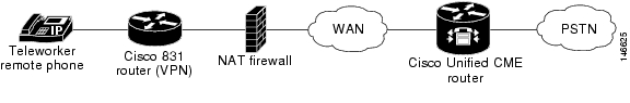
Remote Teleworker Phones
IP phones or instances of Cisco IP Communicator can be connected to a Cisco Unified CME system over a wide area network (WAN) to support teleworkers who have offices that are remote from the Cisco Unified CME router. The maximum number of remote phones that can be supported is determined by the available bandwidth.
IP addressing is a determining factor in the most critical aspect of remote teleworker phone design. The following two scenarios represent the most common designs, the second one is the most common for small and medium businesses:
•
•
–
–
Figure 13 Remote Site IP Phones Using NAT
Media Termination Point for Remote Phones
Media termination point (MTP) configuration is used to ensure that Real-Time Transport Protocol (RTP) media packets from remote phones always transit through the Cisco Unified CME router. Without the MTP feature, a phone that is connected in a call with another phone in the same Cisco Unified CME system sends its media packets directly to the other phone, without the packets going through the Cisco Unified CME router. MTP forces the packets to be sourced from the Cisco Unified CME router.
When this configuration is used to instruct a phone to always send its media packets to the Cisco Unified CME router, the router acts as an MTP or proxy and forwards the packets to the destination phone. If a firewall is present, it can be configured to pass the RTP packets because the router uses a specified UDP port for media packets. In this way, RTP packets from remote IP phones can be delivered to IP phones on the same system though they must pass through a firewall.
You must use the mtp command to explicitly enable MTP for each remote phone that sends media packets to Cisco Unified CME.
One factor to consider is whether you are using multicast music on hold (MOH) in your system. Multicast packets generally cannot be forwarded to phones that are reached over a WAN. The multicast MOH feature checks to see if MTP is enabled for a phone and if it is, MOH is not sent to that phone. If you have a WAN configuration that can forward multicast packets and you can allow RTP packets through your firewall, you can decide not to use MTP.
For configuration information, see the "SCCP: Enabling a Remote Phone" section.
G.729r8 Codec on Remote Phones
You can select the G.729r8 codec on a remote IP phone to help save network bandwidth. The default codec is G.711 mu-law. If you use the codec g729r8 command without the dspfarm-assist keyword, the use of the G.729 codec is preserved only for calls between two phones on the Cisco Unified CME router (such as between an IP phone and another IP phone or between an IP phone and an FXS analog phone). The codec g729r8 command has no affect on a call directed through a VoIP dial peer unless the dspfarm-assist keyword is also used.
For configuration information, see the "SCCP: Enabling a Remote Phone" section.
For information about transcoding behavior when using the G.729r8 codec, see the "Transcoding When a Remote Phone Uses G.729r8" section on page 325.
Digit Collection on SIP Phones
Digit strings dialed by phone users must be collected and matched against predefined patterns to place calls to the destination corresponding to the user's input. Before Cisco Unified CME 4.1, SIP phone users had to press the DIAL soft key or # key, or wait for the interdigit-timeout to trigger call processing. In Cisco United CME 4.1 and later, two methods of collecting and matching digits are supported for SIP phones, depending on the model of phone:
KPML Digit Collection
Key Press Markup Language (KPML) uses SIP SUBSCRIBE and NOTIFY methods to report user input digit by digit. Each digit dialed by the phone user generates its own signaling message to Cisco Unified CME, which performs pattern recognition by matching a destination pattern to a dial peer as it collects the dialed digits. This process of relaying each digit immediately is similar to the process used by SCCP phones. It eliminates the need for the user to press the Dial soft key or wait for the interdigit timeout before the digits are sent to Cisco Unified CME for processing.
KPML is supported on Cisco Unified IP Phones 7911G, 7941G, 7941GE, 7961G, 7961GE, 7970G, and 7971GE. For configuration information, see the "SIP: Enabling KPML" section.
SIP Dial Plans
A dial plan is a set of dial patterns that SIP phones use to determine when digit collection is complete after a user goes off-hook and dials a destination number. Dial plans allow SIP phones to perform local digit collection and recognize dial patterns as user input is collected. After a pattern is recognized, the SIP phone sends an INVITE message to Cisco Unified CME to initiate the call to the number matching the user's input. All of the digits entered by the user are presented as a block to Cisco Unified CME for processing. Because digit collection is done by the phone, dial plans reduce signaling messages overhead compared to KPML digit collection.
SIP dial plans eliminate the need for a user to press the Dial soft key or # key, or to wait for the interdigit timeout to trigger an outgoing INVITE. You configure a SIP dial plan and associate the dial plan with a SIP phone. The dial plan is downloaded to the phone in the configuration file.
You can configure SIP dial plans and associate them with the following SIP phones:
•
If a matching dial plan is not found and KPML is disabled, the user must wait for the interdigit timeout before the SIP NOTIFY message is sent to Cisco Unified CME. Unlike other SIP phones, these phones do not have a Dial soft key to indicate the end of dialing, except when on-hook dialing is used. In this case, the user can press the Dial soft key at any time to send all the dialed digits to Cisco Unified CME.
•
When you reset a phone, the phone requests its configuration files from the TFTP server, which builds the appropriate configuration files depending on the type of phone.
•
•
For configuration information for Cisco Unified CME, see the "SIP: Configuring Dial Plans" section.
Session Transport Protocol for SIP Phones
In Cisco Unified CME 4.1 and later versions, you can select TCP as the transport protocol for connecting supported SIP phones to Cisco Unified CME. Previously only UDP was supported. TCP is selected for individual SIP phones by using the session-transport command in voice register pool or voice register template configuration mode. For configuration information, see the "SIP: Selecting Session-Transport Protocol for a Phone" section.
How to Configure Phones for a PBX System
This section contains the following tasks:
•
•
•
•
•
•
•
•
•
•
SCCP: Creating Directory Numbers
To create a directory number in Cisco Unified CME for a SCCP phone, intercom line, voice port, or a message-waiting indicator (MWI), perform the following steps for each directory number to be created. Each ephone-dn becomes a virtual line, or extension, on which call connections can be made. Each ephone-dn configuration automatically creates one or more virtual dial peers and virtual voice ports to make those call connections.
Note
Prerequisites
•
Restrictions
•
SUMMARY STEPS
1.
2.
3.
4.
5.
6.
DETAILED STEPS
What to Do Next
After creating directory numbers, you can assign one or more directory number to a Cisco Unified IP phone. See "SCCP: Assigning Directory Numbers to Phones" section.
SCCP: Assigning Directory Numbers to Phones
This task sets up the initial ephone-dn-to-ephone relationships—that is, how and which extensions appear on each phone. To create and modify phone-specific parameters for individual SCCP phones, perform the following steps for each SCCP phone to be connected in Cisco Unified CME.
Note
Prerequisites
•
•
Restrictions
•
SUMMARY STEPS
1.
2.
3.
4.
5.
6.
7.
8.
DETAILED STEPS
What to Do Next
•
•
Examples
The following example assigns extension 2225 in the Accounting Department to button 1 on ephone 2.
ephone-dn 25
number 2225
name Accounting
ephone 2
mac-address 00E1.CB13.0395
type 7960
button 1:25
SIP: Creating Directory Numbers
To create a directory number in Cisco Unified CME for a SIP phone, intercom line, voice port, or a message-waiting indicator (MWI), perform the following steps for each directory number to be created. Each directory number becomes a virtual line, or extension, on which call connections can be made. Each directory number configuration automatically creates one or more virtual dial peers and virtual voice ports to make those call connections.
Prerequisites
•
•
Restrictions
•
•
•
SUMMARY STEPS
1.
2.
3.
4.
5.
DETAILED STEPS
SIP: Assigning Directory Numbers to Phones
This task sets up which extensions appear on each phone. To create and modify phone-specific parameters for individual SIP phones, perform the following steps for each SIP phone to be connected in Cisco Unified CME.
Note
SUMMARY STEPS
1.
2.
3.
4.
5.
6.
7.
8.
9.
DETAILED STEPS
What to Do Next
•
•
•
SIP: Configuring Dial Plans
Dial plans enable SIP phones to recognize digit strings dialed by users. After the phone recognizes a dial pattern, it automatically sends a SIP INVITE message to Cisco Unified CME to initiate the call and does not require the user to press the Dial key or wait for the interdigit timeout. To define a dial plan for a SIP phone, perform the following steps.
Prerequisites
•
•
Restrictions
•
•
•
voice register dialplan 10type 7940-7960-otherspattern 1 66...pattern 2 91.......pattern 3 .SUMMARY STEPS
1.
2.
3.
4.
5.
or
filename filename6.
7.
8.
9.
DETAILED STEPS
Step 1
enable
Example:Router> enable
Enables privileged EXEC mode.
•
Step 2
configure terminal
Example:Router# configure terminal
Enters global configuration mode.
Step 3
voice register dialplan dialplan-tag
Example:Router(config)# voice register dialplan 1
Enters voice register dialplan configuration mode to define a dial plan for SIP phones.
Step 4
type phone-type
Example:Router(config-register-dialplan)# type 7905-7912
Defines a phone type for the SIP dial plan.
•
•
•
•
Step 5
pattern tag string [button button-number] [timeout seconds] [user {ip | phone}]
or
filename filename
Example:Router(config-register-dialplan)# pattern 1 52...
or
Router(config-register-dialplan)# filename dialsip
Defines a dial pattern for a SIP dial plan.
•
•
•
•
•
•
•
•
or
Specifies a custom XML file that contains the dial patterns to use for the SIP dial plan.
•
•
Step 6
exit
Example:Router(config-register-dialplan)# exit
Exits dialplan configuration mode.
Step 7
voice register pool pool-tag
Example:Router(config)# voice register pool 4
Enters voice register pool configuration mode to set phone-specific parameters for a SIP phone.
•
Step 8
dialplan dialplan-tag
Example:Router(config-register-pool)# dialplan 1
Assigns a dial plan to a SIP phone.
•
Step 9
end
Example:Router(config-register-global)# end
Exits to privileged EXEC mode.
Examples
The following example shows the configuration for dial plan 1 which is assigned to SIP phone 1.
voice register dialplan 1
type 7940-7960-others
pattern 1 2... timeout 10 user ip
pattern 2 1234 user ip button 4
pattern 3 65...
pattern 4 1...!
!
voice register pool 1
id mac 0016.9DEF.1A70
type 7961GE
number 1 dn 1
number 2 dn 2
dialplan 1
dtmf-relay rtp-nte
codec g711ulaw
What to Do Next
If you are done modifying parameters for SIP phones, you must generate a new configuration profile and restart the phones. See "Generating Configuration Files for Phones" on page 265.
SIP: Verifying Dial Plan Configuration
Step 1
This command displays the configuration information for a specific SIP dial plan.
Router# show voice register dialplan 1Dialplan Tag 1Config:Type is 7940-7960-othersPattern 1 is 2..., timeout is 10, user option is ip, button is defaultPattern 2 is 1234, timeout is 0, user option is ip, button is 4Pattern 3 is 65..., timeout is 0, user option is phone, button is defaultPattern 4 is 1..., timeout is 0, user option is phone, button is defaultStep 2
This command displays the dial plan assigned to a specific SIP phone.
Router# show voice register pool 29Pool Tag 29Config:Mac address is 0012.7F54.EDC6Number list 1 : DN 29Proxy Ip address is 0.0.0.0DTMF Relay is disabledCall Waiting is enabledDnD is disabledkeep-conference is enableddialplan tag is 1kpml signal is enabledservice-control mechanism is not supported...Step 3
This command displays the dial plan assigned to a specific template.
Router# show voice register template 3Temp Tag 3Config:Attended Transfer is disabledBlind Transfer is enabledSemi-attended Transfer is enabledConference is enabledCaller-ID block is disabledDnD control is enabledAnonymous call block is disabledVoicemail is 62000, timeout 15Dialplan Tag is 1Transport type is tcpSIP: Enabling KPML
To enable KPML digit collection on a SIP phone, perform the following steps.
Prerequisites
•
Restrictions
•
•
SUMMARY STEPS
1.
2.
3.
4.
5.
6.
DETAILED STEPS
What to Do Next
If you are done modifying parameters for SIP phones, you must generate a new configuration profile and restart the phones. See "Generating Configuration Files for Phones" on page 265.
SIP: Selecting Session-Transport Protocol for a Phone
To change the session-transport protocol for a SIP phone to TCP, from the default of UDP, perform the following steps.
Prerequisites
•
•
Restrictions
•
SUMMARY STEPS
1.
2.
3.
4.
5.
DETAILED STEPS
What to Do Next
•
•
•
SIP: Disabling SIP Proxy Registration for a Directory Number
To prevent a particular directory number from registering with an external SIP proxy server, perform the following steps.
Prerequisites
•
•
Restrictions
•
SUMMARY STEPS
1.
2.
3.
4.
5.
6.
DETAILED STEPS
What to Do Next
•
•
Configuring Codec for Local Calling Between SIP and SCCP Phones
To designate a codec for individual phones to ensure connectivity between SIP and SCCP phones connected to the same Cisco Unified CME router, perform the following steps for each SIP or SCCP phone.
Note
Prerequisites
•
•
Restrictions
•
•
SUMMARY STEPS
1.
2.
3.
or
voice register pool-tag4.
5.
DETAILED STEPS
What to Do Next
•
•
•
How to Configure Phones for a Key System
This section contains the following tasks:
•
•
•
SCCP: Creating Directory Numbers for a Simple Key System
To create a set of directory numbers with the same number to be associated with multiple line buttons on an IP phone and provide support for call waiting and call transfer on a key system phone, perform the following steps.
Restrictions
•
•
SUMMARY STEPS
1.
2.
3.
4.
5.
6.
or
huntstop7.
8.
DETAILED STEPS
Examples
The following example shows the configuration for six instances of directory number 101, assigned to the first six buttons of an IP phone.
ephone-dn 10
number 101
no huntstop
ephone-dn 11
number 101
preference 1
no huntstop
ephone-dn 12
number 101
preference 2
no huntstop
ephone-dn 13
number 101
preference 3
no huntstop
ephone-dn 14
number 101
preference 4
no huntstop
ephone-dn 15
number 101
preference 5
ephone 1
mac-address 0001.2345.6789
type 7931
button 1:10 2:11 3:12 4:13 5:14 6:15
SCCP: Configuring Trunk Lines for a Key System
To set up trunk lines for your key system, perform only one of the following procedures:
•
•
SCCP: Configuring a Simple Key System Phone Trunk Line Configuration
Perform the steps in this section to:
•
•
Prerequisites
•
voice-port 1/0/0connection plar-opx 801 <<----Private number•
dial-peer voice 111 potsdestination-pattern 811 <<----Trunk-tagport 1/0/0Restrictions
•
•
•
•
•
•
•
•
•
–
–
–
–
•
•
SUMMARY STEPS
1.
2.
3.
4.
5.
6.
DETAILED STEPS
Examples
The following example shows the configuration for six instances of directory number 101, assigned to the first six buttons of an IP phone, plus four PSTN line appearances that are assigned to buttons 7 to 10.
ephone-dn 10
number 101
no huntstop
ephone-dn 11
number 101
preference 1
no huntstop
ephone-dn 12
number 101
preference 2
no huntstop
ephone-dn 13
number 101
preference 3
no huntstop
ephone-dn 14
number 101
preference 4
no huntstop
ephone-dn 15
number 101
preference 5
ephone-dn 51
number 801
trunk 811 monitor-port 1/0/0
ephone-dn 52
number 802
trunk 812 monitor-port 1/0/1
ephone-dn 53
number 803
trunk 813 monitor-port 1/0/2
ephone-dn 54
number 804
trunk 814 monitor-port 1/0/3
ephone 1
mac-address 0001.2345.6789
type 7931
button 1:11 2:12 3:13 4:14 5:15 6:16 7:51 8:52 9:53 10:54
voice-port 1/0/0
connection plar opx 801
voice-port 1/0/1
connection plar opx 802
voice-port 1/0/2
connection plar opx 803
voice-port 1/0/3
connection plar opx 804
dial-peer voice 811 pots
destination-pattern 811
port 1/0/0
dial-peer voice 812 pots
destination-pattern 812
port 1/0/1
dial-peer voice 813 pots
destination-pattern 813
port 1/0/2
dial-peer voice 814 pots
destination-pattern 814
port 1/0/3
What to Do Next
You are ready to configure each individual phone and assign button numbers, line characteristics, and directory numbers to buttons on the phone. See the "SCCP: Configuring Individual IP Phones for Key System" section.
SCCP: Configuring an Advanced Key System Phone Trunk Line Configuration
Perform the steps in this section to:
•
•
•
Prerequisites
•
voice-port 1/0/0connection plar-opx 801 <<----Private number•
dial-peer voice 111 potsdestination-pattern 811 <<----Trunk-tagport 1/0/0Restrictions
•
•
•
•
•
•
•
•
•
–
–
–
–
•
•
•
SUMMARY STEPS
1.
2.
3.
4.
5.
6.
7.
DETAILED STEPS
Examples
The following example shows the configuration for six instances of directory number 101, assigned to the first six buttons of an IP phone, plus four PSTN line appearances that are assigned to buttons 7 to 10. These four PSTN line appearances are configured as dual lines to provide a second call channel on which to place an outbound consultation call during a call transfer attempt. This configuration allows the phone to remain part of the call in order to monitor the progress of the transfer attempt, and if the transfer is not answered, to pull the call back to the phone on the original PSTN line button.
ephone-dn 10
number 101
no huntstop
ephone-dn 11
number 101
preference 1
no huntstop
ephone-dn 12
number 101
preference 2
no huntstop
ephone-dn 13
number 101
preference 3
no huntstop
ephone-dn 14
number 101
preference 4
no huntstop
ephone-dn 15
number 101
preference 5
ephone-dn 51 dual-line
number 801
trunk 811 transfer-timeout 30 monitor-port 1/0/0
huntstop channel
ephone-dn 52 dual-line
number 802
trunk 812 transfer-timeout 30 monitor-port 1/0/1
huntstop channel
ephone-dn 53 dual-line
number 803
trunk 813 transfer-timeout 30 monitor-port 1/0/2
huntstop channel
ephone-dn 54 dual-line
number 804
trunk 814 transfer-timeout 30 monitor-port 1/0/3
huntstop channel
ephone 1
mac-address 0001.2345.6789
type 7931
button 1:11 2:12 3:13 4:14 5:15 6:16 7:51 8:52 9:53 10:54
voice-port 1/0/0
connection plar opx 801
voice-port 1/0/1
connection plar opx 802
voice-port 1/0/2
connection plar opx 803
voice-port 1/0/3
connection plar opx 804
dial-peer voice 811 pots
destination-pattern 811
port 1/0/0
dial-peer voice 812 pots
destination-pattern 812
port 1/0/1
dial-peer voice 813 pots
destination-pattern 813
port 1/0/2
dial-peer voice 814 pots
destination-pattern 814
port 1/0/3
SCCP: Configuring Individual IP Phones for Key System
To assign button numbers, line characteristics, and directory numbers to buttons on an individual phone to operate as a key system phone, perform the following steps.
Restrictions
•
•
•
SUMMARY STEPS
1.
2.
3.
4.
5.
6.
7.
8.
DETAILED STEPS
What to Do Next
•
•
•
How to Configure Cisco ATA, Analog Phone Support, Remote Phones, and Cisco IP Communicator
This section contains the following tasks:
•
•
•
•
•
•
•
•
•
Configuring Cisco ATA Support
To enable an analog phone that uses a Cisco ATA to register with Cisco Unified CME, perform the following steps.
Restrictions
For a Cisco ATA that is registered to a Cisco Unified CME system to participate in fax calls, it must have its ConnectMode parameter set to use the same RTP payload type as the Cisco voice gateway that is performing the fax pass-through. Cisco voice gateways use standard payload type 0/8, which is selected on Cisco ATAs by setting bit 2 of the ConnectMode parameter to 1. For more information, see the " Parameters and Defaults" chapter in the Cisco ATA 186 and Cisco ATA 188 Analog Telephone Adaptor Administrator's Guide for SCCP (version 3.0).
SUMMARY STEPS
1.
2.
3.
4.
5.
DETAILED STEPS
Step 1
Step 2
Step 3
For information about upgrading firmware, see "Installing and Upgrading Cisco Unified CME Software" on page 87. Alternatively, you can use a manual method, as described in the "Upgrading the Cisco ATA Signaling Image" chapter of the Cisco ATA 186 and Cisco ATA 188 Analog Telephone Adaptor Administrator's Guide for SCCP (version 3.0).
Step 4
–
–
–
–
–
–
–
Step 5
What to Do Next
•
•
•
Verifying Cisco ATA Support
Use the show ephone ata command to display SCCP phone configurations with the type ata command.
The following is sample output for a Cisco Unified CME configured for two analog phones using a
Cisco ATA with MAC address 000F.F758.E70E.
ephone-30 Mac:000F.F758.E70E TCP socket:[2] activeLine:0 REGISTERED in SCCP ver 1 and Server in ver 1mediaActive:0 offhook:0 ringing:0 reset:0 reset_sent:0 paging 0 debug:0 caps:7IP:1.4.188.72 15325 ATA Phone keepalive 7 max_line 2 dual-linebutton 1: dn 80 number 8080 CH1 IDLE CH2 IDLEephone-31 Mac:0FF7.58E7.0E01 TCP socket:[3] activeLine:0 REGISTERED in SCCP ver 1 and Server in ver 1mediaActive:0 offhook:0 ringing:0 reset:0 reset_sent:0 paging 0 debug:0 caps:3IP:1.4.188.72 15400 ATA Phone keepalive 7 max_line 2 dual-linebutton 1: dn 81 number 8081 CH1 IDLE CH2 IDLETroubleshooting Cisco ATA Support
Use the debug ephone detail command to diagnose problems with analog phones that use Cisco ATAs. For more information, see the Cisco IOS Debug Command Reference for your Cisco IOS release.
The following is sample output for two analog phones using a Cisco ATA with MAC address 000F.F758.E70E. The sample shows the activities that take place when the phones register.
Router# debug ephone detail mac-address 000F.F758.E70E*Apr 5 02:50:11.966: New Skinny socket accepted [1] (33 active)*Apr 5 02:50:11.970: sin_family 2, sin_port 15325, in_addr 1.4.188.72*Apr 5 02:50:11.970: skinny_add_socket 1 1.4.188.72 1532521:21:49: %IPPHONE-6-REG_ALARM: Name=ATA000FF758E70E Load=ATA030203SCCP051201A.zup Last=Initialized*Apr 5 02:50:11.974:Skinny StationAlarmMessage on socket [2] 1.4.188.72 ATA000FF758E70E*Apr 5 02:50:11.974: severityInformational p1=0 [0x0] p2=0 [0x0]*Apr 5 02:50:11.974: Name=ATA000FF758E70E Load=ATA030203SCCP051201A.zup Last=Initialized*Apr 5 02:50:12.066: ephone-(30)[2] StationRegisterMessage (29/31/48) from 1.4.188.72*Apr 5 02:50:12.066: ephone-(30)[2] Register StationIdentifier DeviceName ATA000FF758E70E*Apr 5 02:50:12.070: ephone-(30)[2] StationIdentifier Instance 1 deviceType 12*Apr 5 02:50:12.070: ephone-30[-1]:stationIpAddr 1.4.188.72*Apr 5 02:50:12.070: ephone-30[-1]:maxStreams 0*Apr 5 02:50:12.070: ephone-30[-1]:protocol Ver 0x1*Apr 5 02:50:12.070: ephone-30[-1]:phone-size 5392 dn-size 632*Apr 5 02:50:12.070: ephone-(30) Allow any Skinny Server IP address 1.4.188.65*Apr 5 02:50:12.070: ephone-30[-1]:Found entry 29 for 000FF758E70E*Apr 5 02:50:12.070: ephone-30[-1]:socket change -1 to 2*Apr 5 02:50:12.070: ephone-30[-1]:FAILED: CLOSED old socket -1*Apr 5 02:50:12.074: ephone-30[2]:phone ATA000FF758E70E re-associate OK on socket [2]21:21:49: %IPPHONE-6-REGISTER: ephone-30:ATA000FF758E70E IP:1.4.188.72 Socket:2 DeviceType:Phone has registered.*Apr 5 02:50:12.074: Phone 29 socket 2*Apr 5 02:50:12.074: Phone 29 socket 2: Running Bravo ??*Apr 5 02:50:12.074: Skinny Local IP address = 1.4.188.65 on port 2000*Apr 5 02:50:12.074: Skinny Phone IP address = 1.4.188.72 15325*Apr 5 02:50:12.074: ephone-30[2]:Signal protocol ver 8 to phone with ver 1*Apr 5 02:50:12.074: ephone-30[2]:Date Format M/D/Y*Apr 5 02:50:12.078: ephone-30[2]:RegisterAck sent to ephone 2: keepalive period 30 use sccp-version 1*Apr 5 02:50:12.078: ephone-30[2]:CapabilitiesReq sent*Apr 5 02:50:12.090: ephone-30[2]:VersionReq received*Apr 5 02:50:12.090: ephone-30[2]:Version String not needed for ATA device. Part of XML file*Apr 5 02:50:12.090: ephone-30[2]:Version Message sent*Apr 5 02:50:12.094: ephone-30[2]:CapabilitiesRes received*Apr 5 02:50:12.098: ephone-30[2]:Caps list 7G711Ulaw64k 60 msG711Alaw64k 60 msG729 60 msG729AnnexA 60 msG729AnnexB 60 msG729AnnexAwAnnexB 60 msUnrecognized Media Type 257 60 ms*Apr 5 02:50:12.098: ephone-30[2]:ButtonTemplateReqMessage*Apr 5 02:50:12.098: ephone-30[2]:StationButtonTemplateReqMessage set max presentation to 2*Apr 5 02:50:12.098: ephone-30[2]:CheckAutoReg*Apr 5 02:50:12.102: ephone-30[2]:AutoReg is disabled*Apr 5 02:50:12.102: ephone-30[2][ATA000FF758E70E]:Setting 1 lines 4 speed-dials on phone (max_line 2)*Apr 5 02:50:12.102: ephone-30[2]:First Speed Dial Button location is 2 (0)*Apr 5 02:50:12.102: ephone-30[2]:Configured 4 speed dial buttons*Apr 5 02:50:12.102: ephone-30[2]:ButtonTemplate lines=1 speed=4 buttons=5 offset=0*Apr 5 02:50:12.102: ephone-30[2]:Skinny IP port 16384 set for socket [2]*Apr 5 02:50:12.126: ephone-30[2]:StationSoftKeyTemplateReqMessage*Apr 5 02:50:12.126: ephone-30[2]:StationSoftKeyTemplateResMessage*Apr 5 02:50:12.206: ephone-30[2]:StationSoftKeySetReqMessage*Apr 5 02:50:12.206: ephone-30[2]:StationSoftKeySetResMessage*Apr 5 02:50:12.307: ephone-30[2]:StationLineStatReqMessage from ephone line 1*Apr 5 02:50:12.307: ephone-30[2]:StationLineStatReqMessage ephone line 1 DN 80 = 8080 desc = 8080 label =*Apr 5 02:50:12.307: ephone-30[2][ATA000FF758E70E]:StationLineStatResMessage sent to ephone (1 of 2)*Apr 5 02:50:12.427: ephone-30[2]:StationSpeedDialStatReqMessage speed 9*Apr 5 02:50:12.427: ephone-30[2]:No speed-dial set 9*Apr 5 02:50:12.427: ephone-30[2]:StationSpeedDialStatMessage sent*Apr 5 02:50:12.547: ephone-30[2]:StationSpeedDialStatReqMessage speed 8*Apr 5 02:50:12.547: ephone-30[2]:No speed-dial set 8*Apr 5 02:50:12.547: ephone-30[2]:StationSpeedDialStatMessage sent*Apr 5 02:50:12.635: ephone-30[2]:StationSpeedDialStatReqMessage speed 7*Apr 5 02:50:12.635: ephone-30[2]:No speed-dial set 7*Apr 5 02:50:12.635: ephone-30[2]:StationSpeedDialStatMessage sent*Apr 5 02:50:12.707: New Skinny socket accepted [1] (34 active)*Apr 5 02:50:12.707: sin_family 2, sin_port 15400, in_addr 1.4.188.72*Apr 5 02:50:12.711: skinny_add_socket 1 1.4.188.72 15400*Apr 5 02:50:12.711: ephone-30[2]:StationSpeedDialStatReqMessage speed 6*Apr 5 02:50:12.711: ephone-30[2]:No speed-dial set 6*Apr 5 02:50:12.715: ephone-30[2]:StationSpeedDialStatMessage sent21:21:50: %IPPHONE-6-REG_ALARM: Name=ATA0FF758E70E01 Load=ATA030203SCCP051201A.zup Last=Initialized*Apr 5 02:50:12.715:Skinny StationAlarmMessage on socket [3] 1.4.188.72 ATA000FF758E70E*Apr 5 02:50:12.715: severityInformational p1=0 [0x0] p2=0 [0x0]*Apr 5 02:50:12.715: Name=ATA0FF758E70E01 Load=ATA030203SCCP051201A.zup Last=Initialized*Apr 5 02:50:12.811: ephone-30[2]:StationSpeedDialStatReqMessage speed 5*Apr 5 02:50:12.811: ephone-30[2]:No speed-dial set 5*Apr 5 02:50:12.811: ephone-30[2]:StationSpeedDialStatMessage sent21:21:50: %IPPHONE-6-REGISTER: ephone-31:ATA0FF758E70E01 IP:1.4.188.72 Socket:3 DeviceType:Phone has registered.*Apr 5 02:50:12.908: ephone-30[2]:StationSpeedDialStatReqMessage speed 4*Apr 5 02:50:12.908: ephone-30[2]:No speed-dial set 4*Apr 5 02:50:12.908: ephone-30[2]:StationSpeedDialStatMessage sent*Apr 5 02:50:13.008: ephone-30[2]:StationSpeedDialStatReqMessage speed 3*Apr 5 02:50:13.008: ephone-30[2]:No speed-dial set 3*Apr 5 02:50:13.008: ephone-30[2]:StationSpeedDialStatMessage sent*Apr 5 02:50:13.108: ephone-30[2]:StationSpeedDialStatReqMessage speed 2*Apr 5 02:50:13.108: ephone-30[2]:No speed-dial set 2*Apr 5 02:50:13.108: ephone-30[2]:StationSpeedDialStatMessage sent*Apr 5 02:50:13.208: ephone-30[2]:StationSpeedDialStatReqMessage speed 1*Apr 5 02:50:13.208: ephone-30[2]:No speed-dial set 1*Apr 5 02:50:13.208: ephone-30[2]:StationSpeedDialStatMessage sent*Apr 5 02:50:14.626: New Skinny socket accepted [1] (33 active)*Apr 5 02:50:14.626: sin_family 2, sin_port 15593, in_addr 1.4.188.72*Apr 5 02:50:14.630: skinny_add_socket 1 1.4.188.72 15593*Apr 5 02:50:15.628: New Skinny socket accepted [1] (34 active)*Apr 5 02:50:15.628: sin_family 2, sin_port 15693, in_addr 1.4.188.72*Apr 5 02:50:15.628: skinny_add_socket 1 1.4.188.72 15693*Apr 5 02:50:21.538: ephone-30[2]:SkinnyCompleteRegistrationUsing Call Pickup and Group Call Pickup with Cisco ATA
Most of the procedures for using Cisco ATAs with Cisco Unified CME are the same as those for using Cisco ATAs with Cisco Unified Communications Manager, as described in the "How to Use Pre-Call and Mid-Call Services" chapter of the Cisco ATA 186 and Cisco ATA 188 Analog Telephone Adaptor Administrator's Guide for SCCP (version 3.0). However, the call pickup and group call pickup procedures are different when using Cisco ATAs with Cisco Unified CME, as described below:
Call Pickup
When using Cisco ATAs with Cisco Unified CME:
•
•
•
Group Call Pickup
When using Cisco ATAs with Cisco Unified CME:
•
•
Note
SCCP: Configuring Analog Phone Support
Configuring Cisco Unified CME to support calls and features on analog endpoints is basically the same as configuring any SCCP phone in Cisco Unified CME. This section describes only the steps that have special meaning for SCCP analog phone support.
Prerequisites
•
•
Restrictions
•
•
•
Note
SUMMARY STEPS
1.
2.
3.
4.
5.
DETAILED STEPS
Step 1
Use the ephone-dn command:
ephone-dn 1 dual-linenumber 1000...ephone-dn 24 dual-linenumber 1024Step 2
Use the max ephones command to set a number equal to or greater than the total number of endpoints that you intend to register on the Cisco Unified CME router, including both IP and analog endpoints. For example, if you have 6 IP phones and 12 analog phones, set the max ephones command to 18 or greater.
Step 3
Use the auto assign command to enable the automatic assignment of an available ephone-dn to each phone as the phone contacts the Cisco Unified CME router to register. Note that the order of ephone-dn assignment is not guaranteed. For example, if you have analog endpoints on ports 2/0 through 2/23 on the Cisco IOS gateway, port 2/0 does not necessarily become ephone 1. Use one of the following commands to enable automatic ephone-dn assignment.
•
•
An alternative to using the auto assign command is to manually assign ephone-dns to ephones (analog phones on FXS ports). This method is more complicated, but you might need to use it if you want to assign a specific extension number (ephone-dn) to a particular ephone. The reason that manual assignment is more complicated is because a unique device ID is required for each registering ephone and analog phones do not have unique MAC addresses like IP phones do. To create unique device IDs for analog phones, the auto assign process uses a particular algorithm. When you make manual ephone assignments, you have to use the same algorithm for each phone that receives a manual assignment. Note that once you have assigned ephone-dns to all the ephones that you want to assign manually, you can use the auto assign command to automatically assign the remaining ports.
The algorithm uses the single 12-digit SCCP local interface MAC address on the Cisco IOS gateway as the base to create unique 12-digit device IDs for all the FXS ports on the Cisco IOS gateway. The rightmost 9 digits of the SCCP local interface MAC address are shifted left three places and are used as the leftmost 9 digits for all 24 individual device IDs. The remaining 3 digits are the hexadecimal translation of the binary representation of the port's slot number (3 digits), subunit number (2 digits), and port number (7 digits). The following example shows the use of the algorithm to create a unique device ID for one port:
1.
2.
3.
When setting up an ephone manually in ephone configuration mode for an analog port, assign it just one button because the port represents a single-line device. The button command can use the ":" (colon, for normal), "o" (overlay) and "c" (call-waiting overlay) modes.
Step 4
•
•
•
•
•
•
•
Step 5
Features such as transfer, conference, park, pickup, group pickup (gpickup), and call forward all (cfwdall) can be restricted from individual ephones using the Cisco Unified CME soft-key template customization command, even though analog phones do not have soft keys. Simply create a template that leaves out the soft key that represents the feature you want to restrict and apply the template to the ephone for which you want the feature restricted. For more information about soft-key template customization, see "Customizing Soft Keys" on page 875.
What to Do Next
•
•
•
SCCP: Verifying Analog Phone Support
Use the following show commands to display information about analog endpoints.
•
•
•
SCCP: Enabling a Remote Phone
To enable IP phones or instances of Cisco IP Communicator to connect to a Cisco Unified CME system over a WAN, perform the following steps.
Prerequisites
•
•
•
Restrictions
•
•
•
We recommend that you make all remote phone users aware of this issue. One way is to place a label on all remote teleworker phones that reminds users not to place 911 emergency calls on remote IP phones. Remote workers should place any emergency calls through locally configured hotel, office, or home phones (normal land-line phones) whenever possible. Inform remote workers that if they must use remote IP phones for emergency calls, they should be prepared to provide specific location information to the answering PSAP personnel, including street address, city, state, and country.
SUMMARY STEPS
1.
2.
3.
4.
5.
6.
DETAILED STEPS
What to Do Next
•
•
•
SCCP: Verifying Remote Phones
Step 1
SCCP: Configuring Cisco IP Communicator Support
To enable support for Cisco IP Communicator, perform the following steps.
Prerequisites
•
•
•
•
DETAILED STEPS
Step 1
The download website is at http://www.cisco.com/cgi-bin/tablebuild.pl/ip-iostsp.
Step 2
Step 3
Step 4
a.
b.
Step 5
Step 6
Use the normal phone provisioning commands described in the "SCCP: Creating Directory Numbers" section. In the type command, use the CIPC keyword to identify this phone as a Cisco IP Communicator.
SCCP: Verifying Cisco IP Communicator Support
Step 1
Step 2
Step 3
SCCP: Troubleshooting Cisco IP Communicator Support
Step 1
Configuration Examples for Making Basic Calls
This section contains the following examples of the required Cisco Unified CME configurations with some of the additional options that are discussed in other modules.
•
•
•
•
Configuring SCCP Phones for Making Basic Calls: Example
Router# show running-config
version 12.4
service tcp-keepalives-in
service tcp-keepalives-out
service timestamps debug datetime msec
service timestamps log datetime msec
no service password-encryption
!
hostname CME40
!
boot-start-marker
boot-end-marker
!
logging buffered 2000000 debugging
!
no aaa new-model
!
resource policy
!
clock timezone PST -8
clock summer-time PDT recurring
no network-clock-participate slot 2
voice-card 0
no dspfarm
dsp services dspfarm
!
voice-card 2
dspfarm
!
no ip source-route
ip cef
!
!
!
ip domain name cisco.com
ip multicast-routing
!
!
ftp-server enable
ftp-server topdir flash:
isdn switch-type primary-5ess
!
!
!
voice service voip
allow-connections h323 to sip
allow-connections sip to h323
no supplementary-service h450.2
no supplementary-service h450.3
h323
call start slow
!
!
!
controller T1 2/0/0
framing esf
linecode b8zs
pri-group timeslots 1-24
!
controller T1 2/0/1
framing esf
linecode b8zs
!
!
interface GigabitEthernet0/0
ip address 192.168.1.1 255.255.255.0
ip pim dense-mode
duplex auto
speed auto
media-type rj45
negotiation auto
!
interface Service-Engine1/0
ip unnumbered GigabitEthernet0/0
service-module ip address 192.168.1.2 255.255.255.0
service-module ip default-gateway 192.168.1.1
!
interface Serial2/0/0:23
no ip address
encapsulation hdlc
isdn switch-type primary-5ess
isdn incoming-voice voice
isdn map address ^.* plan unknown type international
no cdp enable
!
!
ip route 0.0.0.0 0.0.0.0 192.168.1.254
ip route 192.168.1.2 255.255.255.255 Service-Engine1/0
ip route 192.168.2.253 255.255.255.255 10.2.0.1
ip route 192.168.3.254 255.255.255.255 10.2.0.1
!
!
ip http server
ip http authentication local
no ip http secure-server
ip http path flash:
!
!
!
!
tftp-server flash:P00307020300.loads
tftp-server flash:P00307020300.sb2
tftp-server flash:P00307020300.sbn
!
control-plane
!
!
!
voice-port 2/0/0:23
!
!
!
sccp local GigabitEthernet0/0
sccp ccm 192.168.1.1 identifier 1
sccp
!
sccp ccm group 1
associate ccm 1 priority 1
associate profile 1 register MTP0013c49a0cd0
keepalive retries 5
!
dspfarm profile 1 transcode
codec g711ulaw
codec g711alaw
codec g729ar8
codec g729abr8
codec gsmfr
codec g729r8
maximum sessions 90
associate application SCCP
!
!
dial-peer voice 9000 voip
mailbox-selection last-redirect-num
destination-pattern 78..
session protocol sipv2
session target ipv4:192.168.1.2
dtmf-relay sip-notify
codec g711ulaw
no vad
!
dial-peer voice 2 pots
incoming called-number .
direct-inward-dial
port 2/0/0:23
forward-digits all
!
dial-peer voice 1 pots
destination-pattern 9[2-9]......
port 2/0/0:23
forward-digits 8
!
dial-peer voice 3 pots
destination-pattern 91[2-9]..[2-9]......
port 2/0/0:23
forward-digits 12!
!
gateway
timer receive-rtp 1200
!
!
telephony-service
load 7960-7940 P00307020300
max-ephones 100
max-dn 300
ip source-address 192.168.1.1 port 2000
system message CCME 4.0
sdspfarm units 1
sdspfarm transcode sessions 128
sdspfarm tag 1 MTP0013c49a0cd0
voicemail 7800
max-conferences 24 gain -6
call-forward pattern .T
moh music-on-hold.au
multicast moh 239.1.1.1 port 2000
web admin system name admin password sjdfg
transfer-system full-consult
transfer-pattern .T
secondary-dialtone 9
create cnf-files version-stamp Jan 01 2002 00:00:00
!
!
ephone-dn-template 1
!
!
ephone-template 1
keep-conference endcall local-only
codec g729r8 dspfarm-assist
!
!
ephone-template 2
!
!
ephone-dn 1
number 6001
call-forward busy 7800
call-forward noan 7800 timeout 10
!
!
ephone-dn 2
number 6002
call-forward busy 7800
call-forward noan 7800 timeout 10
!
!
ephone-dn 10
number 6013
paging ip 239.1.1.1 port 2000
!
!
ephone-dn 20
number 8000....
mwi on
!
!
ephone-dn 21
number 8001....
mwi off
!
!
!
!
ephone 1
device-security-mode none
username "user1"
mac-address 002D.264E.54FA
codec g729r8 dspfarm-assist
type 7970
button 1:1
!
!
!
ephone 2
device-security-mode none
username "user2"
mac-address 001C.821C.ED23
type 7960
button 1:2
!
!
!
line con 0
stopbits 1
line aux 0
stopbits 1
line 66
no activation-character
no exec
transport preferred none
transport input all
transport output all
line 258
no activation-character
no exec
transport preferred none
transport input all
transport output all
line vty 0 4
exec-timeout 0 0
privilege level 15
password sgpxw
login
!
scheduler allocate 20000 1000
ntp server 192.168.224.18
!
!
end
Configuring SIP Phones for Making Basic Calls: Example
The following is a configuration example for SIP phones running on Cisco Unified CME:
voice service voip
allow-connections sip to sip
sip
registrar server expires max 600 min 60
voice class codec 1
codec preference 1 g711ulaw
voice hunt-group 1 parallel
final 8000
list 2000,1000,2101
timeout 20
pilot 9000
voice hunt-group 2 sequential
final 1000
list 2000,2300
timeout 25
pilot 9100 secondary 9200
voice hunt-group 3 peer
final 2300
list 2100,2200,2101,2201
timeout 15
hops 3
pilot 9300
preference 5
voice hunt-group 4 longest-idle
final 2000
list 2300,2100,2201,2101,2200
timeout 15
hops 5
pilot 9400 secondary 9444
preference 5 secondary 9
voice register global
mode cme
external-ring bellcore-dr3
voice register dn 1
number 2300
mwi
voice register dn 2
number 2200
call-forward b2bua all 1000
call-forward b2bua mailbox 2200
mwi
voice register dn 3
number 2201
after-hour exempt
voice register dn 4
number 2100
call-forward b2bua busy 2000
mwi
voice register dn 5
number 2101
mwi
voice register dn 76
number 2525
call-forward b2bua unreachable 2300
mwi
!
voice register template 1
!
voice register template 2
no conference enable
voicemail 7788 timeout 5
!
voice register pool 1
id mac 000D.ED22.EDFE
type 7960
number 1 dn 1
template 1
preference 1
no call-waiting
codec g711alaw
!
voice register pool 2
id mac 000D.ED23.CBA0
type 7960
number 1 dn 2
number 2 dn 2
template 1
preference 1
dtmf-relay rtp-nte
speed-dial 3 2001
speed-dial 4 2201
!
voice register pool 3
id mac 0030.94C3.053E
type 7960
number 1 dn 3
number 3 dn 3
template 2
!
voice register pool 5
id mac 0012.019B.3FD8
type ATA
number 1 dn 5
preference 1
dtmf-relay rtp-nte
codec g711alaw
voice register pool 6
id mac 0012.019B.3E88
type ATA
number 1 dn 6
number 2 dn 7
template 2
dtmf-relay-rtp-nte
call-forward b2bua all 7778
voice register pool 7
voice register pool 8
id mac 0006.D737.CC42
type 7940
number 1 dn 8
template 2
preference 1
codec g711alaw
voice-port 1/0/0
voice-port 1/0/1
dial-peer voice 100 pots
destination-pattern 2000
port 1/0/0
dial-peer voice 101 pots
destination-pattern 2010
port 1/0/1
dial-peer voice 1001 voip
preference 1
destination-pattern 1...
session protocol sipv2
session target ipv4:10.15.6.13
codec g711ulaw
sip-ua
mwi-server ipv4:1.15.6.200 expires 3600 port 5060 transport udp
telephony-service
load 7960-7940 P0S3-07-2-00
max-ephones 24
max-dn 96
ip source-address 10.15.6.112 port 2000
create cnf-files version-stamp Aug 24 2004 00:00:00
max-conferences 8
after-hours block pattern 1 1...
after-hours day Mon 17:00 07:00
Disabling a Bulk Registration for a SIP Phone: Example
The following example shows the configuration for all phone numbers that match the pattern "408555.." can register with the SIP proxy server (IP address 1.5.49.240) except directory number 1, number "4085550101," for which bulk registration is disabled
voice register global
mode cme
bulk 408555....
voice register dn 1
number 4085550101
no-reg
sip-ua
registrar ipv4:1.5.49.240
Cisco ATA: Example
The following example shows the configuration for two analog phones using a single Cisco ATA with MAC address 000F.F758.E70E. The analog phone attached to the first port uses the MAC address of the Cisco ATA. The analog phone attached to the second port uses a modified version of the Cisco ATA's MAC address; the first two hexadecimal numbers are removed and 01 is appended to the end.
!
telephony-service
conference hardware
load ATA ATA030203SCCP051201A.zup
!
ephone-dn 80 dual-line
number 8080
!
ephone-dn 81 dual-line
number 8081
!
ephone 30
mac-address 000F.F758.E70E
type ata
button 1:80
!
ephone 31
mac-address 0FF7.58E7.0E01
type ata
button 1:81
SCCP Analog Phone: Example
The following excerpt from a Cisco Unified CME configuration sets transfer type to full-blind and sets the voice-mail extension to 5200. Ephone-dn 10 has the extension 4443 and is assigned to Tommy; that number and name will be used for caller-ID displays. The description field under ephone-dn is used to indicate that this ephone-dn is on the Cisco VG 224 voice gateway at port 1/3. Extension 4443 is assigned to ephone 7, which is an analog phone type with 10 speed-dial numbers.
CME_Router# show running-config
.
.
.
telephony-service
load 7910 P00403020214
load 7960-7940 P00305000301
load 7905 CP79050101SCCP030530B31
max-ephones 60
max-dn 60
ip source-address 10.8.1.2 port 2000
auto assign 1 to 60
create cnf-files version-stamp 7960 Sep 28 2004 17:23:02
voicemail 5200
mwi relay
mwi expires 99999
max-conferences 8 gain -6
web admin system name cisco password lab
web admin customer name ac2 password cisco
dn-webedit
time-webedit
transfer-system full-blind
transfer-pattern 6...
transfer-pattern 5...
!
!
ephone-dn 10 dual-line
number 4443 secondary 9191114443
pickup-group 5
description vg224-1/3
name tommy
!
ephone 7
mac-address C863.9018.0402
speed-dial 1 4445
speed-dial 2 4445
speed-dial 3 4442
speed-dial 4 4441
speed-dial 5 6666
speed-dial 6 1111
speed-dial 7 1112
speed-dial 8 9191114441
speed-dial 9 9191114442
speed-dial 10 9191114442
type anl
button 1:10
!
Remote Teleworker Phones: Example
The following example shows the configuration for ephone 270, a remote teleworker phone with its codec set to G.729r8. The dspfarm-assist keyword is used to ensure that calls from this phone will use DSP resources to maintain the G.729r8 codec when calls would normally be switched to a G.711 codec.
ephone 270
button 1:36
mtp
codec g729r8 dspfarm-assist
description teleworker remote phone
Where to Go Next
To select a fixed-button layout for a Cisco Unified IP Phone 7931G, see "SCCP: Selecting Button Layout for a Cisco Unified IP Phone 7931G" on page 943 .
After configuring phones in Cisco Unified CME to make basic calls, you are ready to generate configuration files for the phones to be connected to your router. See "Generating Configuration Files for Phones" on page 265.
Additional References
The following sections provide references related to Cisco Unified CME features.
Related Documents
Cisco Unified CME configuration
•
Cisco IOS commands
•
Cisco IOS configuration
•
Phone documentation for Cisco Unified CME
Technical Assistance
Feature Information for Configuring Phones to Make Basic Calls
Table 11 lists the features in this module and enhancements to the features by version.
To determine the correct Cisco IOS release to support a specific Cisco Unified CME version, see the Cisco Unified CME and Cisco IOS Software Version Compatibility Matrix at http://www.cisco.com/en/US/products/sw/voicesw/ps4625/products_documentation_roadmap09186a0080189132.html.
Use Cisco Feature Navigator to find information about platform support and software image support. Cisco Feature Navigator enables you to determine which Cisco IOS software images support a specific software release, feature set, or platform. To access Cisco Feature Navigator, go to http://www.cisco.com/go/cfn. An account on Cisco.com is not required.
Note
![]()
![]()
![]()
![]()
![]()
![]()
![]()
![]()
Posted: Tue Sep 25 13:42:16 PDT 2007
All contents are Copyright © 1992--2007 Cisco Systems, Inc. All rights reserved.
Important Notices and Privacy Statement.