|
|

Table Of Contents
Calling Name and Number Feature
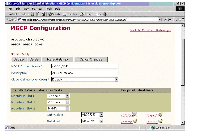
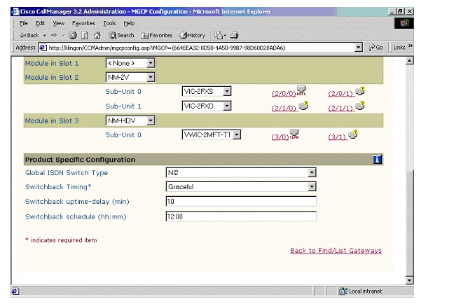
MGCP (Cisco 3640) Gateway Configuration
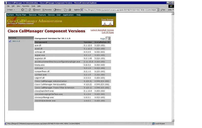
CallManager Components Release
Cisco 3640 Router Configuration
Application Note
NEC 2400 ICS PBX with CallManager using 3640-T1 MGCP Gateway
This application note illustrates connectivity for NEC 2400 ICS PBX with CallManager using 3640-T1 MGCP Gateway.
Introduction
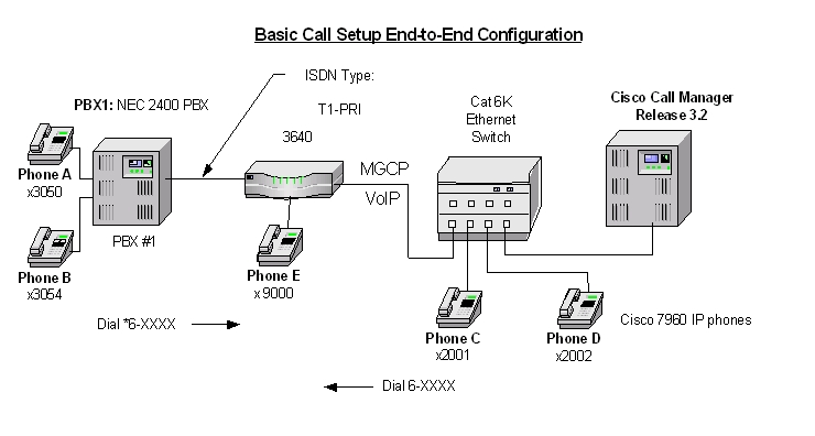
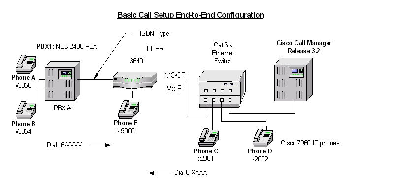
The network topology diagram presented in Figure 1 illustrates the test set-up for end-to-end interoperability between the Cisco CallManager connected to the PBX via Cisco 3640-T1 link as MGCP Gateway.
Key test environment parameters:
•
Calling Name delivery and presentation features are not supported by the NEC 2400 ICS PBX. Calling Name is supported on the NEC IMX platform using software Release 9 or higher with the NI2 protocol.
•
•
Network Diagram
Figure 1
Network Test Topology
Limitations
Calling Name and Number Feature
1.
2.
System Components
Hardware Requirements
Cisco Hardware:
•
•
•
NEC 2400 ICS PBX:
•
Software Requirements
•
•
J 05.80 00/06/20 Generic
F 01.00 96/04/26 Boot ROM
•
Feature
Key features supported:
•
Key features not supported:
•
•
Configuration
Configuration tasks consist of:
1.
2.
3.
4.
5.
NEC 2400 ICS Configuration
The NEC requires a substantial amount of programming and circuit card switch settings to properly install T1 PRI. It is beyond the scope of this document to provide the entire configuration, therefore the NEC information below is mostly helpful for NEC techs. If further assistance is required, the entire configuration of our lab PBX can be found in EDCS document # EDCS-207455. The EDCS document provides the programs required for T1 ISDN circuit setup, all the switch settings for all cards on our Lab NEC and fairly complete configuration listings (List Ups).
Note:
Configure in the following sequence:
1.
2.
Route (ARTD) Configuration
Below are the Route settings found in ARTD. Route 7 is the B channel and Route 8 is the D channel. Please refer to EDCS document # EDCS-207455 for complete details for configuration.
[LRTD] CISCO TEST FACILITY 02/05/10 PAGE: 3* ROUTE CLASS DATA LIST *------- R O U T E N U M B E R -------CDN FUNCTION 6 7 8 9 101 OSGS 0 2 2 2 22 ONSG 2 3 3 3 33 ISGS 0 2 2 2 24 INSG 2 3 3 3 35 TF 3 3 3 3 36 TCL 4 4 4 4 47 L/T 1 1 1 1 18 RLP 2 2 2 2 29 TQ 0 0 0 0 010 SMDR 0 1 1 1 011 TD 0 0 0 0 012 DR 0 0 0 0 013 AC 1 1 1 1 114 TNT 0 0 0 0 015 LSG 13 12 13 12 1316 SMDR2 0 0 0 0 017 H/M 0 0 0 0 018 MC 0 0 0 0 019 ANI 0 0 0 0 020 D 0 0 0 0 021 MSB 0 0 0 0 022 MSW 0 0 0 0 023 TR 0 0 0 0 024 OC 0 0 0 0 025 R/L 0 0 0 0 026 RVSD 0 0 0 0 027 TL 0 0 0 0 028 ANS 0 1 1 1 029 TELP 0 0 0 0 030 PAD 7 4 7 4 731 OGRL 0 1 0 1 032 ICRL 0 1 0 1 033 HD 0 0 0 0 034 GUARD 0 1 0 1 035 WINK 0 0 0 0 036 VAD 0 0 0 0 037 CLD 0 0 0 0 038 FA 0 0 0 0 0[LRTD] CISCO TEST FACILITY 02/05/10 PAGE: 4* ROUTE CLASS DATA LIST *------- R O U T E N U M B E R -------CDN FUNCTION 6 7 8 9 1039 BC 0 0 0 0 040 TCM 0 0 0 0 041 TDMQ 0 0 0 0 042 TRSC 0 0 0 0 043 BT 0 1 1 0 044 PRV 0 0 0 0 045 A/D 1 1 1 1 146 CW 0 0 0 0 047 TPQ 0 0 0 0 048 BL 0 0 0 0 049 TRKS 1 0 0 0 050 DPLY 1 1 0 1 051 ACD 0 0 0 0 052 2W/4W 0 0 0 0 053 FAAT 0 0 0 0 054 GW 0 0 0 0 055 TCMA 0 0 0 0 056 SMDR3 0 0 0 0 057 HDT 0 0 0 0 058 CD 0 0 0 0 059 CCH 0 0 0 0 060 TC/EC 0 0 0 0 061 IRE 0 0 0 0 062 SCR 0 0 0 0 063 LYER1 0 0 0 0 064 NET 0 0 0 0 065 INT 10 1 1 1 166 DC 4 4 4 4 467 HKS 0 0 0 0 068 SCF 0 0 0 0 069 SMDR4 0 0 0 0 0MGCP (Cisco 3640) Gateway Configuration
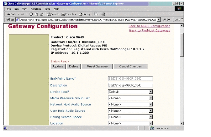
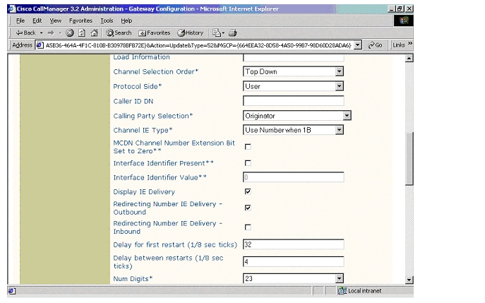
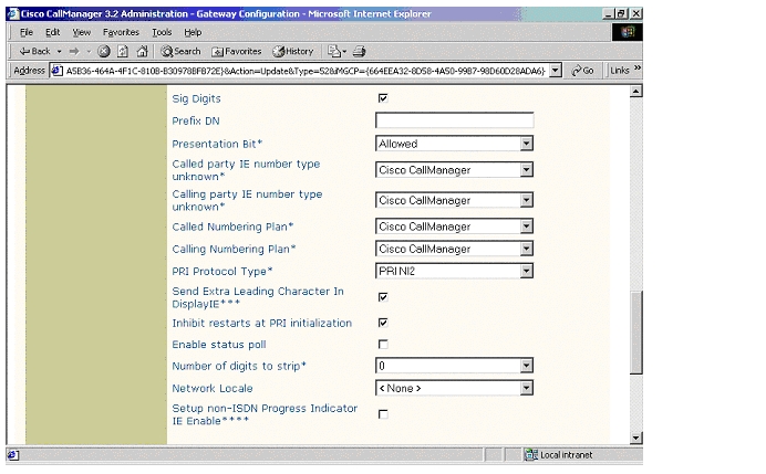
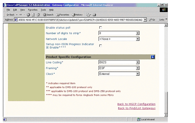
ISDN PRI Configuration
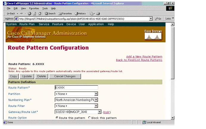
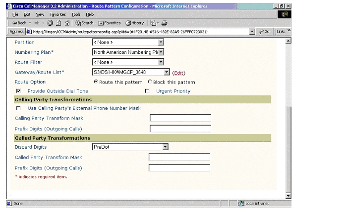
Route Pattern Configuration
Appendix A
CallManager Software Release
NEC Software Release
DISS 02/05/10 16:06 CISCO TEST FACILITYMMVERSION ISSUE DATEJ 05.80 00/06/20 GenericMMVERSION ISSUE DATEF_ 01.00 96/04/26 Boot ROMDISS END 02/05/10 16:07CallManager Components Release
Cisco 3640 Router Configuration
MGCP_3640#sh verCisco Internetwork Operating System SoftwareIOS (tm) 3600 Software (C3640-JS-M), Experimental Version 12.2(20020124:013600) [accheung-v122_xn_throttle.build 101]Copyright (c) 1986-2002 by cisco Systems, Inc.Compiled Wed 23-Jan-02 17:57 by accheungImage text-base: 0x60008948, data-base: 0x61608000ROM: System Bootstrap, Version 11.1(19)AA, EARLY DEPLOYMENT RELEASE SOFTWARE (fc1)MGCP_3640 uptime is 1 hour, 40 minutesSystem returned to ROM by power-onSystem image file is "flash:c3640-js-mz"cisco 3640 (R4700) processor (revision 0x00) with 58368K/7168K bytes of memory.Processor board ID 10620494R4700 CPU at 100Mhz, Implementation 33, Rev 1.0Channelized E1, Version 1.0.Bridging software.X.25 software, Version 3.0.0.SuperLAT software (copyright 1990 by Meridian Technology Corp).TN3270 Emulation software.Primary Rate ISDN software, Version 1.1.2 Ethernet/IEEE 802.3 interface(s)55 Serial network interface(s)2 Channelized E1/PRI port(s)2 Channelized T1/PRI port(s)2 Voice FXO interface(s)2 Voice FXS interface(s)DRAM configuration is 64 bits wide with parity disabled.125K bytes of non-volatile configuration memory.16384K bytes of processor board System flash (Read/Write)16384K bytes of processor board PCMCIA Slot0 flash (Read/Write)Configuration register is 0x2102MGCP_3640#sh diagSlot 0:Combo 2E, 2W Port adapter, 4 portsPort adapter is analyzedPort adapter insertion time unknownEEPROM contents at hardware discovery:Hardware revision 1.2 Board revision B0Serial number 7687836 Part number 800-01171-04Test history 0x0 RMA number 00-00-00EEPROM format version 1EEPROM contents (hex):0x20: 01 1E 01 02 00 75 4E 9C 50 04 93 04 00 00 00 000x30: 58 00 00 00 98 02 28 17 FF FF FF FF FF FF FF FFSlot 1:High Density Voice Port adapterPort adapter is analyzedPort adapter insertion time unknownEEPROM contents at hardware discovery:Hardware Revision : 1.1Top Assy. Part Number : 800-03567-01Board Revision : F1Deviation Number : 0-0Fab Version : 02PCB Serial Number : JAB05080M1SRMA Test History : 00RMA Number : 0-0-0-0RMA History : 00EEPROM format version 4EEPROM contents (hex):0x00: 04 FF 40 00 CC 41 01 01 C0 46 03 20 00 0D EF 010x10: 42 46 31 80 00 00 00 00 02 02 C1 8B 4A 41 42 300x20: 35 30 38 30 4D 31 53 03 00 81 00 00 00 00 04 000x30: FF FF FF FF FF FF FF FF FF FF FF FF FF FF FF FF0x40: FF FF FF FF FF FF FF FF FF FF FF FF FF FF FF FF0x50: FF FF FF FF FF FF FF FF FF FF FF FF FF FF FF FF0x60: FF FF FF FF FF FF FF FF FF FF FF FF FF FF FF FF0x70: FF FF FF FF FF FF FF FF FF FF FF FF FF FF FF FFWIC Slot 0:E1 (2 Port) Multi-Flex Trunk WAN Daughter CardHardware revision 1.0 Board revision B0Serial number 18779824 Part number 800-04479-01Test history 0x0 RMA number 00-00-00Connector type PCIEEPROM format version 1EEPROM contents (hex):0x20: 01 23 01 00 01 1E 8E B0 50 11 7F 01 00 00 00 000x30: 58 00 00 00 00 02 25 00 FF FF FF FF FF FF FF FFHDV firmware: Compiled Fri 23-Mar-01 00:20 by miriyalaHDV memory size 524280 heap free 175065Slot 2:4 PORT Voice PM for MARs Port adapterPort adapter is analyzedPort adapter insertion time unknownEEPROM contents at hardware discovery:Hardware revision 1.1 Board revision C0Serial number 10689987 Part number 800-02491-02Test history 0x0 RMA number 00-00-00EEPROM format version 1EEPROM contents (hex):0x20: 01 65 01 01 00 A3 1D C3 50 09 BB 02 00 00 00 000x30: 60 00 00 00 98 11 22 17 FF FF FF FF FF FF FF FFWIC Slot 0:FXS Voice daughter card (2 port)Hardware revision 1.1 Board revision C0Serial number 11291019 Part number 800-02493-01Test history 0x0 RMA number 00-00-00Connector type Wan ModuleEEPROM format version 1EEPROM contents (hex):0x20: 01 0E 01 01 00 AC 49 8B 50 09 BD 01 00 00 00 000x30: 60 00 00 00 99 01 05 01 FF FF FF FF FF FF FF FFWIC Slot 1:FXO Voice daughter card (2 port)Hardware revision 1.1 Board revision C0Serial number 8421533 Part number 800-02495-01Test history 0x0 RMA number 00-00-00Connector type Wan ModuleEEPROM format version 1EEPROM contents (hex):0x20: 01 0D 01 01 00 80 80 9D 50 09 BF 01 00 00 00 000x30: 60 00 00 00 98 06 02 01 FF FF FF FF FF FF FF FFSlot 3:High Density Voice Port adapterPort adapter is analyzedPort adapter insertion time unknownEEPROM contents at hardware discovery:Hardware Revision : 1.0Top Assy. Part Number : 800-03567-01Board Revision : A0Deviation Number : 0-0Fab Version : 02PCB Serial Number : JAB03350B9KRMA Test History : 00RMA Number : 0-0-0-0RMA History : 00EEPROM format version 4EEPROM contents (hex):0x00: 04 FF 40 00 CC 41 01 00 C0 46 03 20 00 0D EF 010x10: 42 41 30 80 00 00 00 00 02 02 C1 8B 4A 41 42 300x20: 33 33 35 30 42 39 4B 03 00 81 00 00 00 00 04 000x30: FF FF FF FF FF FF FF FF FF FF FF FF FF FF FF FF0x40: FF FF FF FF FF FF FF FF FF FF FF FF FF FF FF FF0x50: FF FF FF FF FF FF FF FF FF FF FF FF FF FF FF FF0x60: FF FF FF FF FF FF FF FF FF FF FF FF FF FF FF FF0x70: FF FF FF FF FF FF FF FF FF FF FF FF FF FF FF FFWIC Slot 0:T1 (2 Port) Multi-Flex Trunk (Drop&Insert) WAN Daughter CardHardware revision 1.0 Board revision A0Serial number 19621702 Part number 800-04614-02Test history 0x0 RMA number 00-00-00Connector type PCIEEPROM format version 1EEPROM contents (hex):0x20: 01 24 01 00 01 2B 67 46 50 12 06 02 00 00 00 000x30: 50 00 00 00 00 05 20 00 FF FF FF FF FF FF FF FFHDV firmware: Compiled Fri 23-Mar-01 00:20 by miriyalaHDV memory size 524280 heap free 175065MGCP_3640#sh controller t1T1 3/0 is up.Applique type is Channelized T1Cablelength is long gain36 0dbNo alarms detected.alarm-trigger is not setVersion info Firmware: 20010315, FPGA: 15Framing is ESF, Line Code is B8ZS, Clock Source is Line.Data in current interval (5 seconds elapsed):0 Line Code Violations, 0 Path Code Violations0 Slip Secs, 0 Fr Loss Secs, 0 Line Err Secs, 0 Degraded Mins0 Errored Secs, 0 Bursty Err Secs, 0 Severely Err Secs, 0 Unavail SecsMGCP_3640# sh confUsing 2266 out of 129016 bytes!version 12.2no parser cacheno service single-slot-reload-enableservice timestamps debug uptimeservice timestamps log uptimeno service password-encryptionno service dhcp!hostname MGCP_3640!logging rate-limit console 10 except errors!!!voice-card 1!voice-card 3!ip subnet-zero!!!no ip dhcp-client network-discoverymgcpmgcp call-agent 10.1.1.2 2427 service-type mgcp version 0.1mgcp dtmf-relay voip codec all mode out-of-bandmgcp rtp unreachable timeout 1000 action notifymgcp modem passthrough voip mode ciscomgcp sdp simplemgcp package-capability rtp-packagemgcp package-capability sst-packageno mgcp timer receive-rtcpno mgcp explicit hookstateisdn switch-type primary-nicall rsvp-sync!!!!!ccm-manager mgcpccm-manager music-on-holdccm-manager config server 10.1.1.2ccm-manager config!!controller E1 1/0pri-group timeslots 1-31 service mgcp!controller E1 1/1!controller T1 3/0framing esflinecode b8zspri-group timeslots 1-24 service mgcp!controller T1 3/1framing sflinecode ami!!!interface Ethernet0/0ip address 10.1.1.200 255.255.255.0no ip mroute-cachehalf-duplex!interface Ethernet0/1ip address 171.69.231.23 255.255.255.0no ip mroute-cachehalf-duplex!interface Serial1/0:15no ip addressno logging event link-statusisdn switch-type primary-net5isdn incoming-voice voiceisdn T310 4000isdn bind-l3 ccm-managerno cdp enable!interface Serial3/0:23no ip addressno logging event link-statusisdn switch-type primary-niisdn protocol-emulate networkisdn incoming-voice voiceisdn T306 30000isdn T310 40000isdn bind-l3 ccm-managerno cdp enable!ip classlessno ip http server!!!!snmp-server manager!voice-port 1/0:15!voice-port 2/0/0!voice-port 2/0/1!voice-port 2/1/0!voice-port 2/1/1!voice-port 3/0:23!dial-peer cor custom!!!dial-peer voice 1 potsapplication mgcp!dial-peer voice 3 potsapplication mgcpappport 2/0/1!dial-peer voice 2 potsapplication mgcpappport 2/0/0!dial-peer voice 999200 potsapplication mgcpappport 2/0/0!dial-peer voice 9991015 potsapplication mgcpappport 1/0:15!dial-peer voice 9993023 potsapplication mgcpappport 3/0:23!!line con 0line aux 0line vty 0 4login!!endMGCP_3640#sh runBuilding configuration...Current configuration : 2266 bytes!version 12.2no parser cacheno service single-slot-reload-enableservice timestamps debug uptimeservice timestamps log uptimeno service password-encryptionno service dhcp!hostname MGCP_3640!logging rate-limit console 10 except errors!!!voice-card 1!voice-card 3!ip subnet-zero!!!no ip dhcp-client network-discoverymgcpmgcp call-agent 10.1.1.2 2427 service-type mgcp version 0.1mgcp dtmf-relay voip codec all mode out-of-bandmgcp rtp unreachable timeout 1000 action notifymgcp modem passthrough voip mode ciscomgcp sdp simplemgcp package-capability rtp-packagemgcp package-capability sst-packageno mgcp timer receive-rtcpno mgcp explicit hookstateisdn switch-type primary-nicall rsvp-sync!!!!!ccm-manager mgcpccm-manager music-on-holdccm-manager config server 10.1.1.2ccm-manager config!!controller E1 1/0pri-group timeslots 1-31 service mgcp!controller E1 1/1!controller T1 3/0framing esflinecode b8zspri-group timeslots 1-24 service mgcp!controller T1 3/1framing sflinecode ami!!!interface Ethernet0/0ip address 10.1.1.200 255.255.255.0no ip mroute-cachehalf-duplex!interface Ethernet0/1ip address 171.69.231.23 255.255.255.0no ip mroute-cachehalf-duplex!interface Serial1/0:15no ip addressno logging event link-statusisdn switch-type primary-net5isdn incoming-voice voiceisdn T310 4000isdn bind-l3 ccm-managerno cdp enable!interface Serial3/0:23no ip addressno logging event link-statusisdn switch-type primary-niisdn protocol-emulate networkisdn incoming-voice voiceisdn T306 30000isdn T310 40000isdn bind-l3 ccm-managerno cdp enable!ip classlessno ip http server!!!!snmp-server manager!voice-port 1/0:15!voice-port 2/0/0!voice-port 2/0/1!voice-port 2/1/0!voice-port 2/1/1!voice-port 3/0:23!dial-peer cor custom!!!dial-peer voice 1 potsapplication mgcp!dial-peer voice 3 potsapplication mgcpappport 2/0/1!dial-peer voice 2 potsapplication mgcpappport 2/0/0!dial-peer voice 999200 potsapplication mgcpappport 2/0/0!dial-peer voice 9991015 potsapplication mgcpappport 1/0:15!dial-peer voice 9993023 potsapplication mgcpappport 3/0:23!!line con 0line aux 0line vty 0 4login!!endMGCP_3640#Test Configuration
Figure 2
Test Topology
As shown in the diagram above, a NEC 2400 ICS PBX was connected via an ISDN T1 PRI link to a Cisco 3640 Gateway, which in turn, was connected to an Ethernet switch. The interoperability testing involved Layers 1, 2 and 3 on the ISDN PRI link between a Cisco 3640 and the PBX.
Layers 2 & 3 (Q.921 and Q.931)
Layer 2 and 3 packet exchanges were monitored using an Acacia Clarinet protocol analyzer, bridged across the PRI link in high impedance mode.
Layer 2 Q.921 packets were monitored to ensure that each PBX/3640 software configuration properly exchanged SABME/UA packets to initialize the ISDN link, and then RR packets were exchanged every 30 seconds.
Layer 3 Q.931 packets were monitored to ensure that the appropriate call setup/teardown packets were exchanged for each configuration, and that the SETUP packets contained the mandatory Information Elements with the necessary details, as well as optional IEs such as Calling Name and Number.
Telephone calls were made end-to-end in both directions through the Cisco 3640 Gateway, and a check was made to ensure that there was an audio path in both directions for each call.
User/Network Settings
The Cisco 3640 Gateway with ISDN protocol type setting of PRI-NI2 supports both protocol sides by selecting "Network/User" in the protocol side field when configuring the Gateway via Callmanager.
Though the NEC 2400 ICS can be configured as either NETWORK (Master) or USER (Slave) side, configuration as NETWORK is not recommended. The NEC TAC center will not resolve a case presented with NEC set as the NETWORK side.
Appendix B
Test Results
Testing was performed by Test Engineer(s): Samir Batio and Bob Graves, March 11, 2002
Test Setup
Test configuration:
•
•
Note:
![]()
![]()
![]()
![]()
![]()
![]()
![]()
![]()
Posted: Thu Sep 6 12:11:28 PDT 2007
All contents are Copyright © 1992--2007 Cisco Systems, Inc. All rights reserved.
Important Notices and Privacy Statement.