|
|

Table Of Contents
Cisco Systems Equipment Needed
PBX Hardware and Software Requirements
Configuring the Lucent/Avaya Definity G3si PBX
Lucent/Avaya Definity G3si Software Release
Cisco 3640 Router Configuration
Application Note
Lucent/Avaya Definity G3si V9 PBX with CallManager using the Cisco VG200-T1 CAS as an MGCP Gateway
This application note discusses the integration of the Lucent/Avaya Definity G3si V9 PBX with CallManager using the Cisco VG200-T1 CAS as an MGCP Gateway.
Integration Description
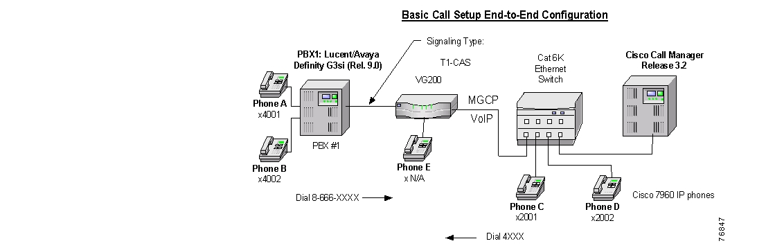
? Connectivity is achieved by using the T1-CAS signaling protocol type on the MGCP gateway and the Lucent/Avaya PBX. The figure below shows the general network layout for the integration.
Network Layout
Cisco Systems Equipment Needed
•
Hardware (Gateway): Cisco VG200 Gateway with 2MFT T1 Port
•
PBX Hardware and Software Requirements
•
•
Features
Key features supported:
•
•
Key features not supported:
•
Configuring the Lucent/Avaya Definity G3si PBX
To configure the Lucent/Avaya Definity G3si PBX, do the following:
Step 1.
Step 2.
Step 3.
Step 4.
Circuit Pack
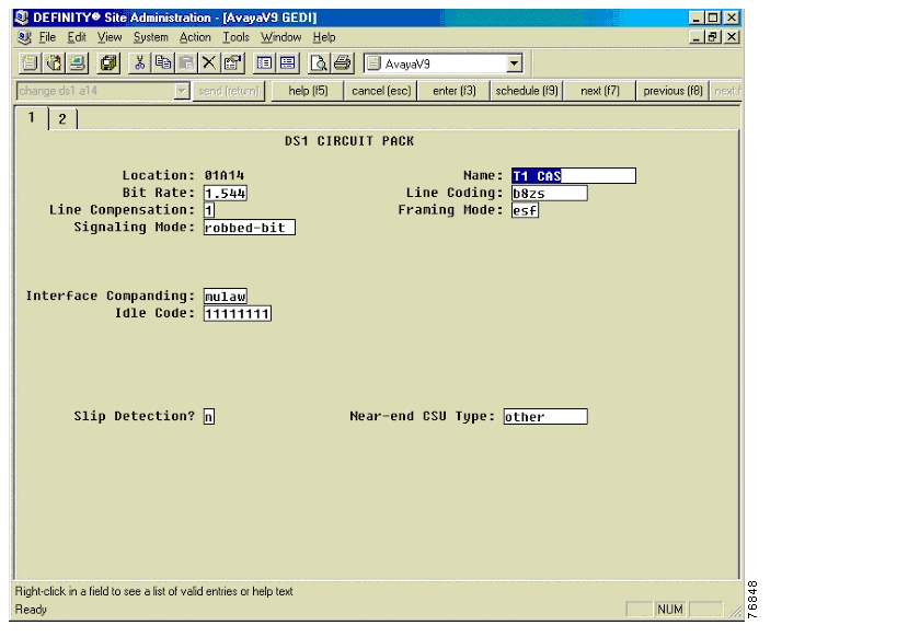
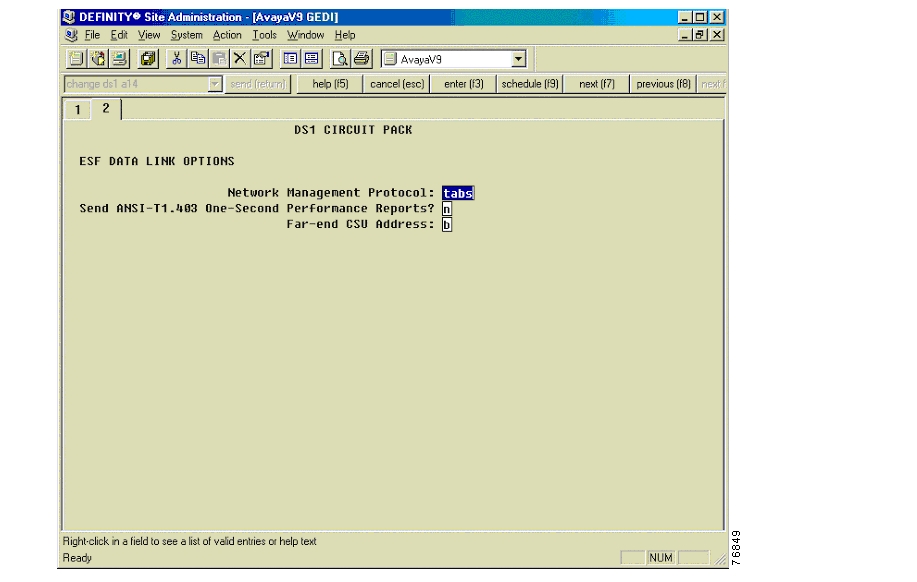
The following figures show the configuration of the DS1 circuit pack.
DS1 Circuit Pack
DS1 Circuit Pack—ESF Data Link Options
Trunk Group
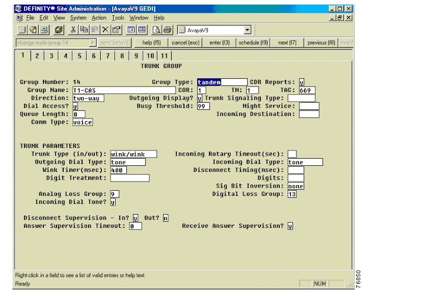
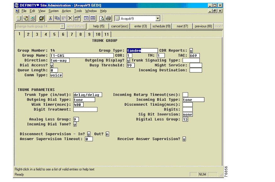
The following figures show the configuration of the trunk group.
Trunk Group for Wink-Start Signaling
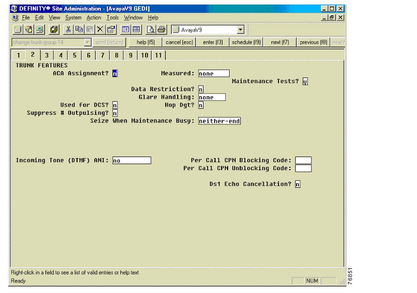
Trunk Group—Trunk Features
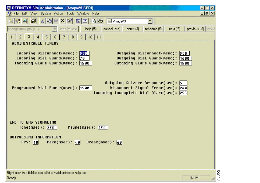
Trunk Group—Administrable Times
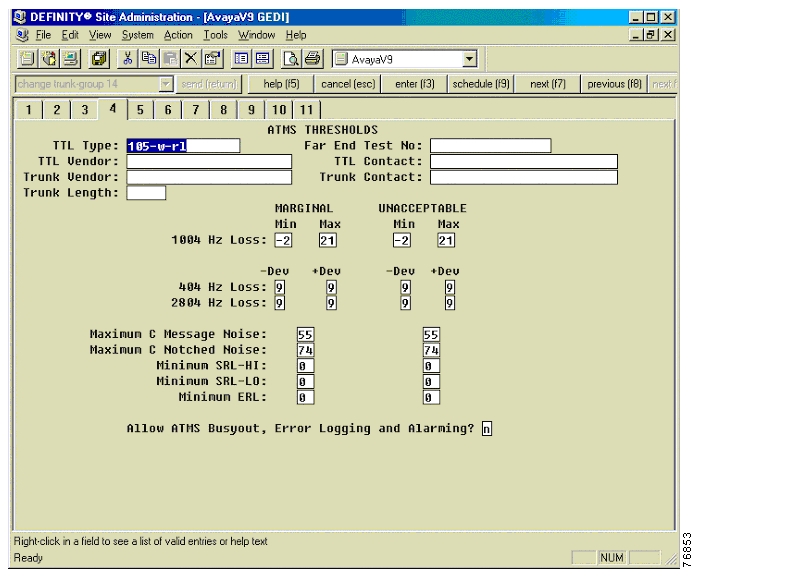
Trunk Group—ATMS Thresholds
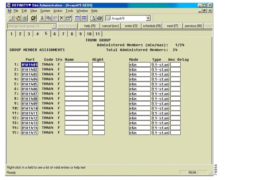
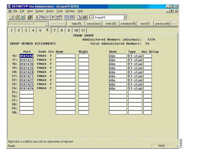
Trunk Group—Group Member Assignments
Trunk Group—Group Member Assignments Continued
Trunk Group for Delay-Dial Signaling
Uniform Dialing Plan
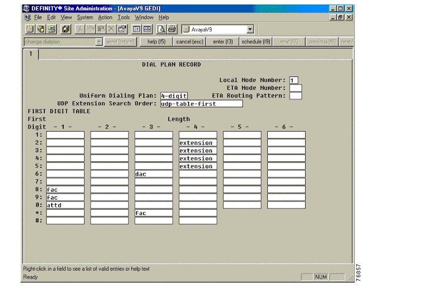
The following figures show the configuration of the uniform dialing plan.
Dial Plan Record
Pattern Number
Configuring Cisco CallManager
To configure Cisco CallManager, do the following:
Step 1.
Step 2.
Gateway Configuration
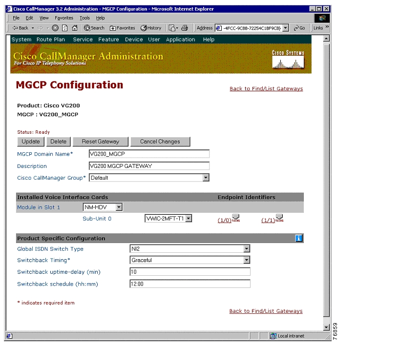
The following figures show the configuration of the VG200 MGCP Gateway.
Cisco VG200 MGCP Gateway Configuration
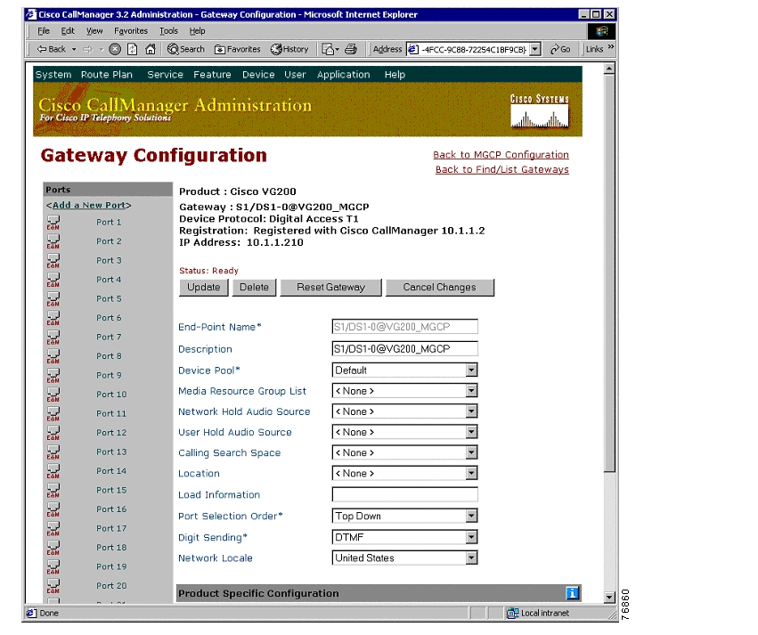
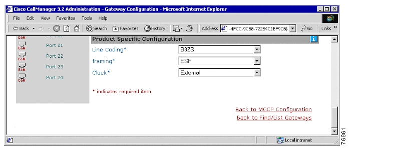
Digital Access T1-CAS Configuration
Digital Access T1-CAS Configuration Continued
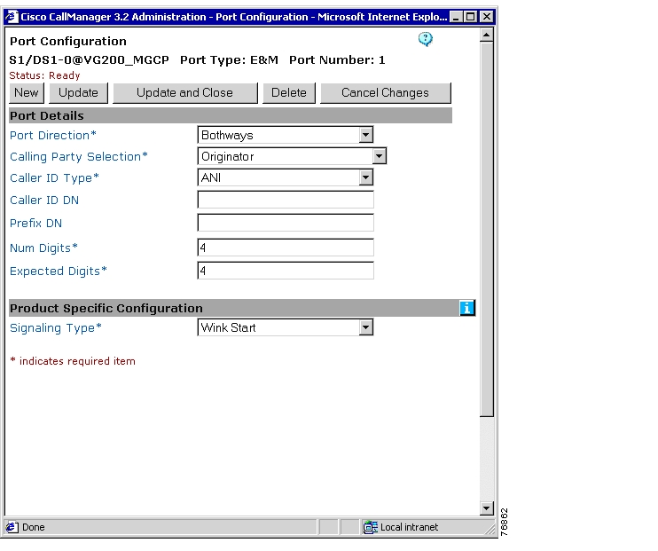
T1-CAS Port Configuration
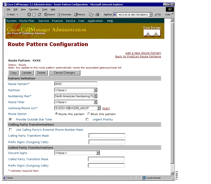
Route Pattern Configuration
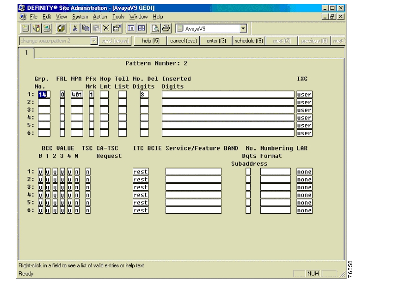
The following figure shows the configuration of the route pattern.
Route Pattern Configuration
Considerations
E&M-Immediate-Start Signaling
E&M-Immediate-start Signaling type is not supported on CCM Gateway configuration GUI.
E&M-Delay-Dial Signaling
E&M-Delay-Dial signaling is not functional when the default timer setting (300msec) for the Delay-Start parameter is used on the Gateway. Because this timer parameter cannot be changed by the CCM Gateway configuration GUI, the Wink Timer trunk parameter on the Lucent/Avaya PBX must be changed from the default of 300 msec to 400msec for the Delay-Dial signaling type to work properly.
Note:
Wink-Start signaling is best choice for reliability.
Integration Testing
This section contains information about the setup used in testing the integration of the Lucent/Avaya Definity G3si V9 PBX with CallManager using the Cisco VG200 as an MGCP Gateway.
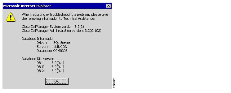
CallManager Software Release:
The following figure shows the information about the release of CallManager being used.
CallManager Software Release
Lucent/Avaya Definity G3si Software Release
The following release of the Lucent/Avaya Definity G3si was used:
•
•
Cisco 3640 Router Configuration
The following shows the configuration of the Cisco 3640 router.
VG200_MGCP#show versionCisco Internetwork Operating System SoftwareIOS (tm) VG200 Software (VG200-I6S-M), Version 12.2(2)XN, EARLY DEPLOYMENT RELEASE SOFTWARE (fc2)TAC Support: http://www.cisco.com/tacCopyright (c) 1986-2002 by cisco Systems, Inc.Compiled Fri 01-Mar-02 08:20 by eaarmasImage text-base: 0x80008088, data-base: 0x8087FC2CROM: System Bootstrap, Version 12.1(1r) [phanguye 1r], RELEASE SOFTWARE (fc1)ROM: VG200 Software (VG200-I6S-M), Version 12.2(2)XN, EARLY DEPLOYMENT RELEASE SOFTWARE (fc2)VG200_MGCP uptime is 1 week, 2 days, 1 minuteSystem returned to ROM by power-onSystem image file is "flash:vg200-i6s-mz.122-2.XN"cisco VG200 (MPC860) processor (revision 0x102) with 26624K/6144K bytes of memory.Processor board ID JAB04400CNJ (0)M860 processor: part number 0, mask 49Primary Rate ISDN software, Version 1.1.1 FastEthernet/IEEE 802.3 interface(s)2 Channelized T1/PRI port(s)32K bytes of non-volatile configuration memory.8192K bytes of processor board System flash (Read/Write)Configuration register is 0x2102VG200_MGCP#_______________________________________________________________________________________VG200_MGCP#show diagSlot 0:VG200 1FE Mainboard Port adapter, 1 portPort adapter is analyzedPort adapter insertion time unknownEEPROM contents at hardware discovery:Hardware Revision : 1.2PCB Serial Number : JAB04400CNJ (0)Part Number : 73-4742-01RMA History : 00RMA Number : 0-0-0-0Board Revision : A0Deviation Number : 0-0EEPROM format version 4EEPROM contents (hex):0x00: 04 FF 40 00 94 41 01 02 C1 0F 4A 41 42 30 34 340x10: 30 30 43 4E 4A 20 28 30 29 82 49 12 86 01 04 000x20: 81 00 00 00 00 42 41 30 80 00 00 00 00 FF FF FF0x30: FF FF FF FF FF FF FF FF FF FF FF FF FF FF FF FF0x40: FF FF FF FF FF FF FF FF FF FF FF FF FF FF FF FF0x50: FF FF FF FF FF FF FF FF FF FF FF FF FF FF FF FF0x60: FF FF FF FF FF FF FF FF FF FF FF FF FF FF FF FF0x70: FF FF FF FF FF FF FF FF FF FF FF FF FF FF FF FFSlot 1:High Density Voice Port adapterPort adapter is analyzedPort adapter insertion time unknownEEPROM contents at hardware discovery:Hardware Revision : 1.0Top Assy. Part Number : 800-03567-01Board Revision : A0Deviation Number : 0-0Fab Version : 02PCB Serial Number : JAB034004D1RMA Test History : 00RMA Number : 0-0-0-0RMA History : 00EEPROM format version 4EEPROM contents (hex):0x00: 04 FF 40 00 CC 41 01 00 C0 46 03 20 00 0D EF 010x10: 42 41 30 80 00 00 00 00 02 02 C1 8B 4A 41 42 300x20: 33 34 30 30 34 44 31 03 00 81 00 00 00 00 04 000x30: FF FF FF FF FF FF FF FF FF FF FF FF FF FF FF FF0x40: FF FF FF FF FF FF FF FF FF FF FF FF FF FF FF FF0x50: FF FF FF FF FF FF FF FF FF FF FF FF FF FF FF FF0x60: FF FF FF FF FF FF FF FF FF FF FF FF FF FF FF FF0x70: FF FF FF FF FF FF FF FF FF FF FF FF FF FF FF FFVIC Slot 0:T1 (2 Port) Multi-Flex Trunk WAN Daughter CardHardware revision 1.0 Board revision B0Serial number 19766455 Part number 800-04615-01Test history 0x0 RMA number 00-00-00Connector type PCIEEPROM format version 1EEPROM contents (hex):0x20: 01 22 01 00 01 2D 9C B7 50 12 07 01 00 00 00 000x30: 58 00 00 00 00 04 19 00 FF FF FF FF FF FF FF FFHDV firmware: Compiled Fri 23-Mar-01 00:20 by miriyalaHDV memory size 524280 heap free 197609_______________________________________________________________________________________VG200_MGCP#show controllers t1 1/0T1 1/0 is up.Applique type is Channelized T1Cablelength is long gain36 0dbNo alarms detected.alarm-trigger is not setVersion info Firmware: 20010315, FPGA: 15Framing is ESF, Line Code is B8ZS, Clock Source is Line.Data in current interval (78 seconds elapsed):0 Line Code Violations, 0 Path Code Violations0 Slip Secs, 0 Fr Loss Secs, 0 Line Err Secs, 0 Degraded Mins0 Errored Secs, 0 Bursty Err Secs, 0 Severely Err Secs, 0 Unavail SecsVG200_MGCP#VG200_MGCP#show runningBuilding configuration...Current configuration : 1301 bytes!version 12.2no parser cacheno service single-slot-reload-enableno service padservice timestamps debug uptimeservice timestamps log uptimeno service password-encryption!hostname VG200_MGCP!logging rate-limit console 10 except errors!voice-card 1!ip subnet-zero!no ip dhcp-client network-discoverymgcpmgcp call-agent 10.1.1.2 2427 service-type mgcp version 0.1mgcp dtmf-relay voip codec all mode out-of-bandmgcp rtp unreachable timeout 1000 action notifymgcp modem passthrough voip mode ciscomgcp sdp simplemgcp package-capability rtp-packagemgcp package-capability sst-packageno mgcp timer receive-rtcpno mgcp explicit hookstatecall rsvp-sync!!!!!ccm-manager mgcpccm-manager music-on-holdccm-manager config server 10.1.1.2ccm-manager config!controller T1 1/0framing esflinecode b8zsds0-group 1 timeslots 1-24 type e&m-wink-start!controller T1 1/1framing esflinecode b8zs!!interface FastEthernet0/0ip address 10.1.1.210 255.255.255.0duplex autospeed auto!ip classlessno ip http server!!voice-port 1/0:1!dial-peer voice 100 potsapplication mgcpapp!dial-peer voice 200 potsapplication mgcpapp!dial-peer voice 999101 potsapplication mgcpappport 1/0:1!!line con 0line aux 0line vty 0 4loginline vty 5 15login!endVG200_MGCP#Test Configuration
The following figure represents the various configurations used for testing.
Testbed Network Configuration
As shown in the figure above, a Lucent/Avaya Definity G3si PBX was connected via a T1-CAS link to a Cisco VG200 Gateway, which in turn, was connected to an Ethernet switch. The interoperability testing involved basic call setup functionality between the CCM and the Lucent/Avaya PBX.
The objective was to test the VG200 Digital T1 interface over the T1-CAS signaling options on the Lucent/Avaya Definity G3si PBX by testing basic call setup functionality to verify the voice path in both directions of the call between the CCM and the Lucent/Avaya Definity G3si PBX
Test Results
Testing was performed by Test Engineer(s): Samir Batio, June 17, 2002
Test 1
In test 1:
•
•
The results are shown in the following table.
.
Test 2
In test 2:
•
•
The results are shown in the following table.
.
![]()
![]()
![]()
![]()
![]()
![]()
![]()
![]()
Posted: Thu Sep 6 12:26:24 PDT 2007
All contents are Copyright © 1992--2007 Cisco Systems, Inc. All rights reserved.
Important Notices and Privacy Statement.