|
|

Table Of Contents
Cisco Systems Equipment Needed
Configuring the Lucent/Avaya Definity G3si PBX
Calling Name and Number Feature
Lucent/Avaya Definity G3si Software Release
Cisco 3640 Router Configuration
Application Note
Lucent/Avaya Definity G3si V9 PBX with CallManager using the Cisco 3640-T1 PRI as an MGCP Gateway
This application note discusses the integration of the Lucent/Avaya Definity G3si V9 PBX with CallManager using the Cisco 3640-T1 PRI as an MGCP Gateway.
Integration Description
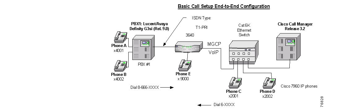
Connectivity is achieved by using the industry standard PRI NI-2 protocol. The Lucent/Avaya Definity G3si can be configured as either the NETWORK or USER side. The figure below shows the general network layout for the integration.
Network Layout
Cisco Systems Equipment Needed
•
Hardware (Gateway): Cisco 3640 Gateway with 2MFT T1 Port
•
PBX Requirements
•
•
Features
Key features supported:
•
•
•
Key features not supported:
•
Configuring the Lucent/Avaya Definity G3si PBX
To configure the Lucent/Avaya Definity G3si PBX, do the following:
Step 1.
Step 2.
Step 3.
Step 4.
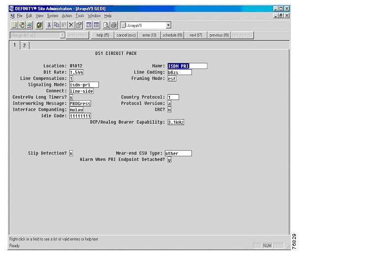
Circuit Pack
The following figures show the configuration of the DS1 circuit pack.
DS1 Circuit Pack
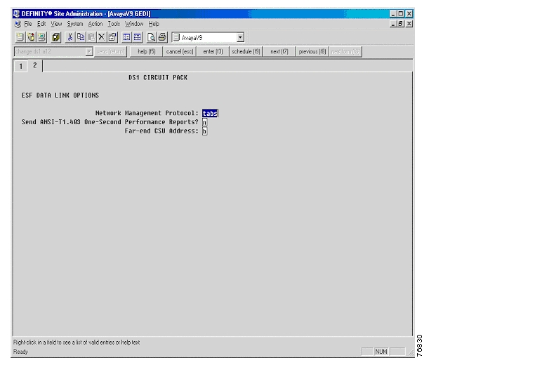
DS1 Circuit Pack—ESF Data Link Options
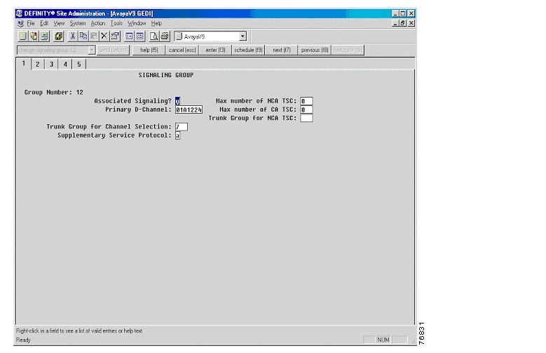
Signaling Group
The following figure shows the configuration of the signaling group.
Signaling Group
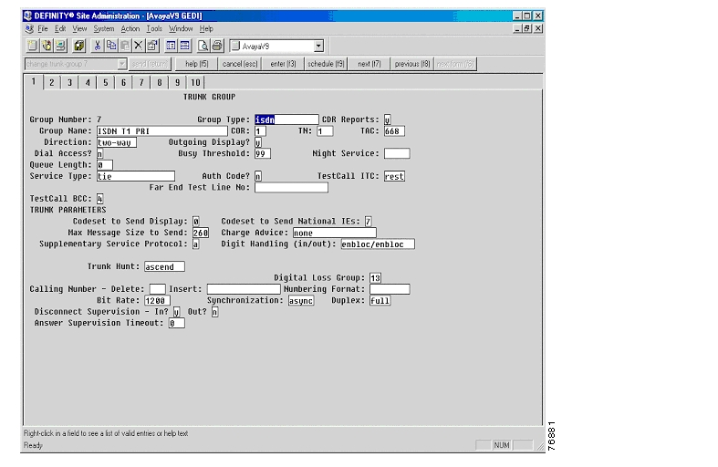
Trunk Group
The following figures show the configuration of the trunk group.
Trunk Group
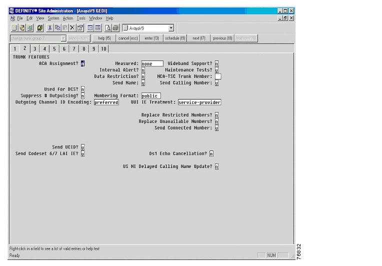
Trunk Group—Trunk Features
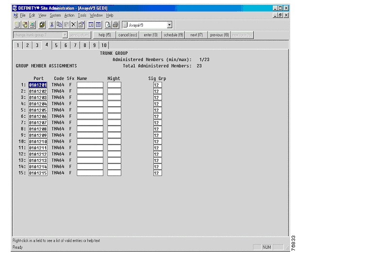
Trunk Group—Group Member Assignments
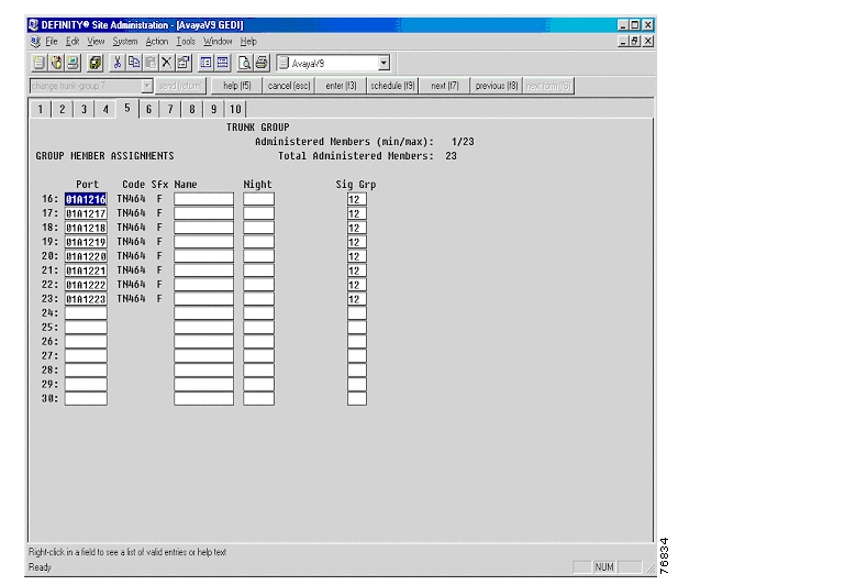
Trunk Group—Group Member Assignments Continued
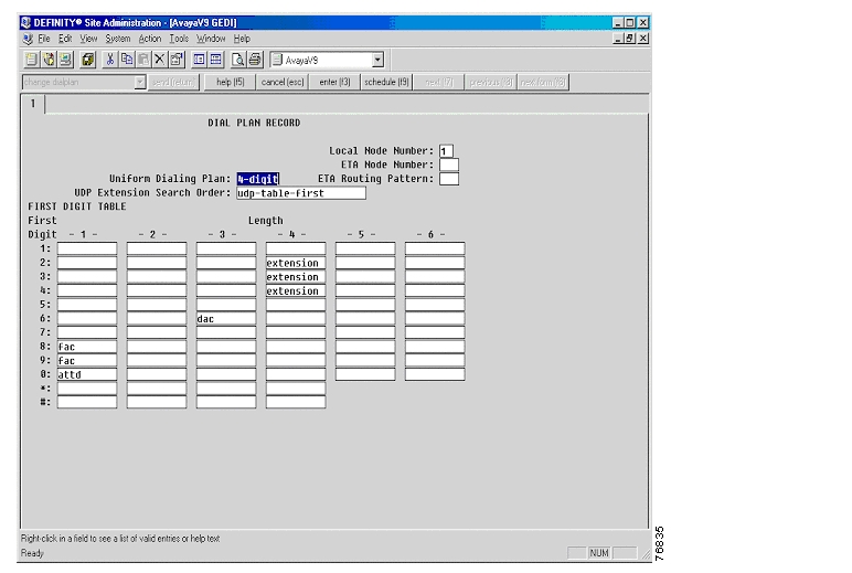
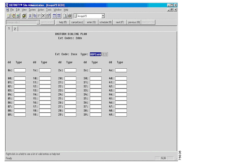
Uniform Dialing Plan
The following figures show the configuration of the uniform dialing plan.
Dial Plan Record
Uniform Dialing Plan
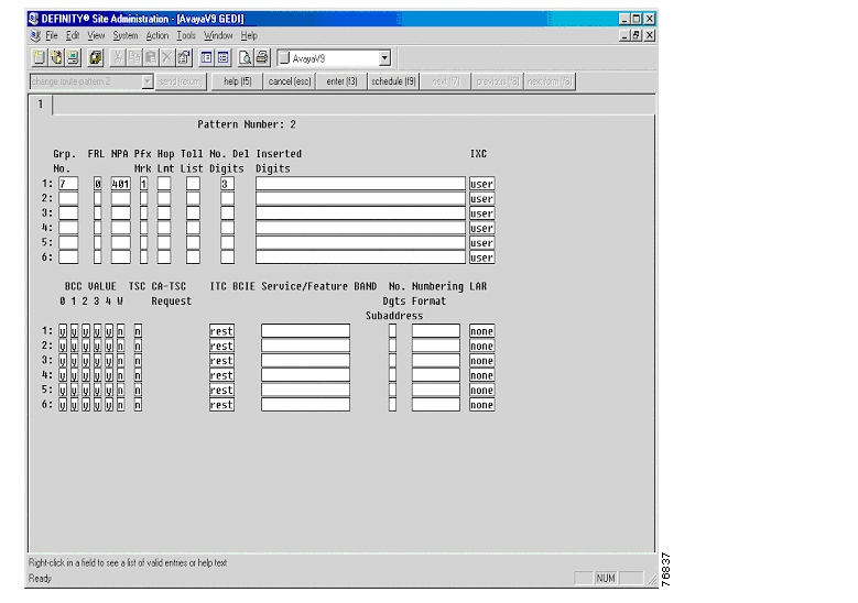
Pattern Number
Configuring Cisco CallManager
To configure Cisco CallManager, do the following:
Step 1.
Step 2.
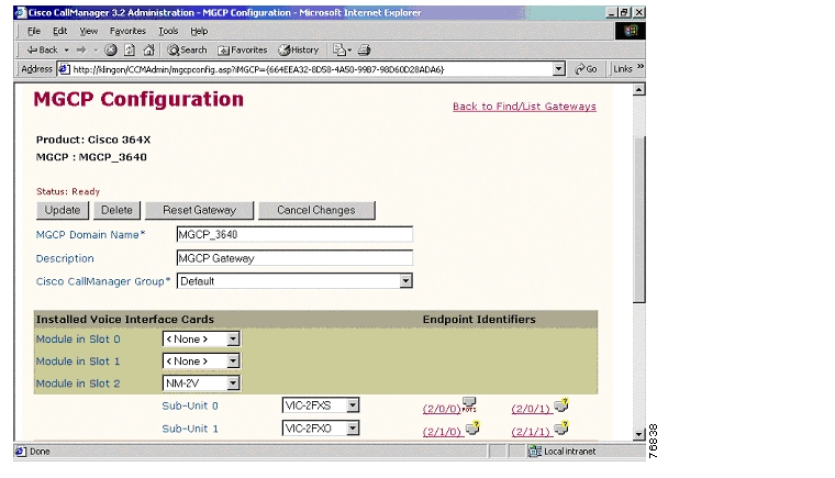
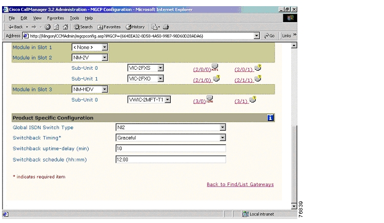
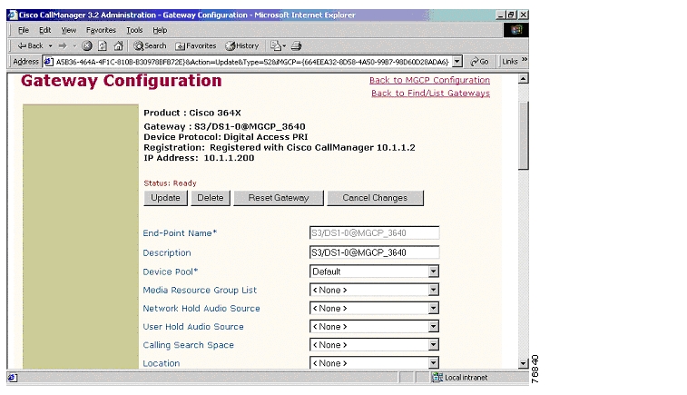
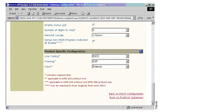
Gateway Configuration
The following figures show the configuration of the Cisco 3640 MGCP Gateway.
Cisco 3640 MGCP Gateway Configuration
Cisco 3640 MGCP Gateway Configuration Continued
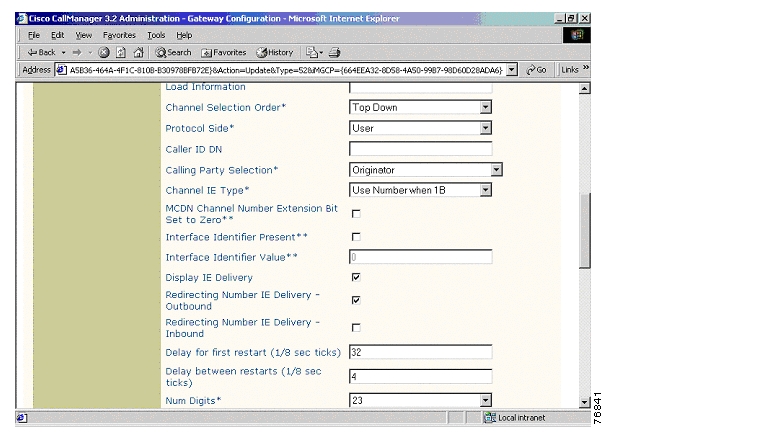
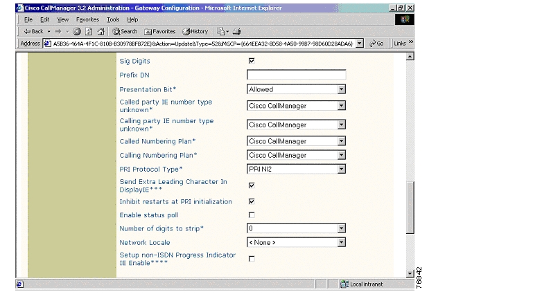
ISDN PRI Configuration
ISDN PRI Configuration Continued
ISDN PRI Configuration Continued
ISDN PRI Configuration Continued
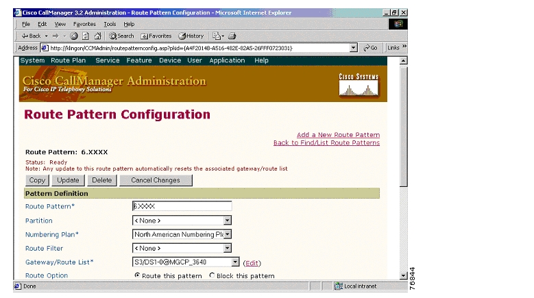
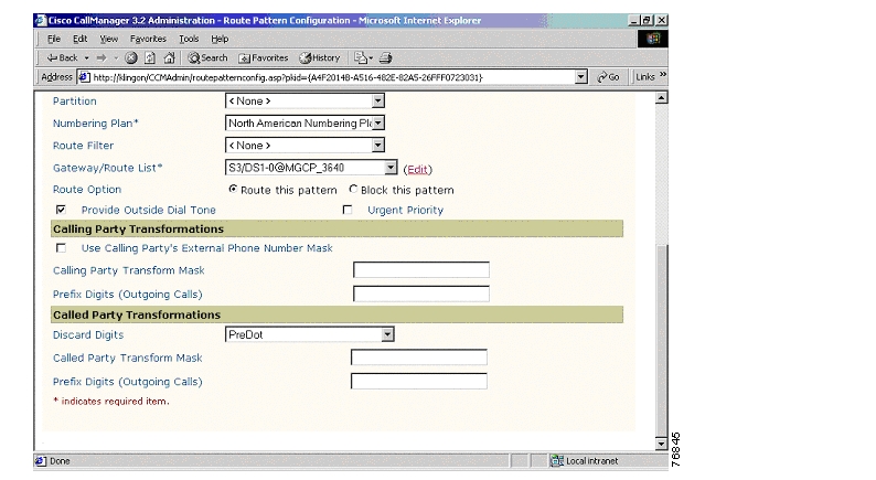
Route Pattern Configuration
The following figures show the configuration of the route pattern.
Route Pattern Configuration
Route Pattern Configuration Continued
Considerations
Calling Name and Number Feature
When calling from a Cisco 7960 IP phone to a Lucent/Avaya digital phone, both phones display Calling Name and Number after the call is answered as expected.
When calling from a Lucent/Avaya digital phone to a Cisco 7960 IP phone, the IP phone displays the Connected Name and Number after the call is answered. The Lucent/Avaya phone, however, displays the Called Name but does not display the Called Number. It was verified using ISDN protocol analyzer that the CallManager was not sending the Connected Number information in the connect message back to PBX.
Integration Testing
This section contains information about the setup used in testing the integration of the Lucent/Avaya Definity G3si V9 PBX with CallManager using the Cisco 3640-T1 PRI as an MGCP Gateway.
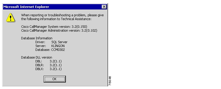
CallManager Software Release:
The following figure shows the information about the release of CallManager being used.
CallManager Software Release
Lucent/Avaya Definity G3si Software Release
The following release of the Lucent/Avaya Definity G3si was used:
•
•
Cisco 3640 Router Configuration
The following shows the configuration of the Cisco 3640 router.
MGCP_3640#show versionCisco Internetwork Operating System SoftwareIOS (tm) 3600 Software (C3640-JS-M), Experimental Version 12.2(20020124:013600) [accheung-v122_xn_throttle.build 101]Copyright (c) 1986-2002 by cisco Systems, Inc.Compiled Wed 23-Jan-02 17:57 by accheungImage text-base: 0x60008948, data-base: 0x61608000ROM: System Bootstrap, Version 11.1(19)AA, EARLY DEPLOYMENT RELEASE SOFTWARE (fc1)MGCP_3640 uptime is 4 days, 2 hours, 11 minutesSystem returned to ROM by power-onSystem image file is "flash:c3640-js-mz.122-2.XN"cisco 3640 (R4700) processor (revision 0x00) with 59392K/6144K bytes of memory.Processor board ID 10620494R4700 CPU at 100Mhz, Implementation 33, Rev 1.0Bridging software.X.25 software, Version 3.0.0.SuperLAT software (copyright 1990 by Meridian Technology Corp).TN3270 Emulation software.Primary Rate ISDN software, Version 1.1.2 Ethernet/IEEE 802.3 interface(s)24 Serial network interface(s)2 Channelized T1/PRI port(s)2 Voice FXO interface(s)2 Voice FXS interface(s)DRAM configuration is 64 bits wide with parity disabled.125K bytes of non-volatile configuration memory.16384K bytes of processor board System flash (Read/Write)16384K bytes of processor board PCMCIA Slot0 flash (Read/Write)Configuration register is 0x2102_______________________________________________________________________________________MGCP_3640#show diagSlot 0:Combo 2E, 2W Port adapter, 4 portsPort adapter is analyzedPort adapter insertion time unknownEEPROM contents at hardware discovery:Hardware revision 1.2 Board revision B0Serial number 7687836 Part number 800-01171-04Test history 0x0 RMA number 00-00-00EEPROM format version 1EEPROM contents (hex):0x20: 01 1E 01 02 00 75 4E 9C 50 04 93 04 00 00 00 000x30: 58 00 00 00 98 02 28 17 FF FF FF FF FF FF FF FFSlot 2:4 PORT Voice PM for MARs Port adapterPort adapter is analyzedPort adapter insertion time unknownEEPROM contents at hardware discovery:Hardware revision 1.1 Board revision C0Serial number 10689987 Part number 800-02491-02Test history 0x0 RMA number 00-00-00EEPROM format version 1EEPROM contents (hex):0x20: 01 65 01 01 00 A3 1D C3 50 09 BB 02 00 00 00 000x30: 60 00 00 00 98 11 22 17 FF FF FF FF FF FF FF FFWIC Slot 0:FXS Voice daughter card (2 port)Hardware revision 1.1 Board revision C0Serial number 11291019 Part number 800-02493-01Test history 0x0 RMA number 00-00-00Connector type Wan ModuleEEPROM format version 1EEPROM contents (hex):0x20: 01 0E 01 01 00 AC 49 8B 50 09 BD 01 00 00 00 000x30: 60 00 00 00 99 01 05 01 FF FF FF FF FF FF FF FFWIC Slot 1:FXO Voice daughter card (2 port)Hardware revision 1.1 Board revision C0Serial number 8421533 Part number 800-02495-01Test history 0x0 RMA number 00-00-00Connector type Wan ModuleEEPROM format version 1EEPROM contents (hex):0x20: 01 0D 01 01 00 80 80 9D 50 09 BF 01 00 00 00 000x30: 60 00 00 00 98 06 02 01 FF FF FF FF FF FF FF FFSlot 3:High Density Voice Port adapterPort adapter is analyzedPort adapter insertion time unknownEEPROM contents at hardware discovery:Hardware Revision : 1.0Top Assy. Part Number : 800-03567-01Baord Revision : A0Deviation Number : 0-0Fab Version : 02PCB Serial Number : JAB03350B9KRMA Test History : 00RMA Number : 0-0-0-0RMA History : 00EEPROM format version 4EEPROM contents (hex):0x00: 04 FF 40 00 CC 41 01 00 C0 46 03 20 00 0D EF 010x10: 42 41 30 80 00 00 00 00 02 02 C1 8B 4A 41 42 300x20: 33 33 35 30 42 39 4B 03 00 81 00 00 00 00 04 000x30: FF FF FF FF FF FF FF FF FF FF FF FF FF FF FF FF0x40: FF FF FF FF FF FF FF FF FF FF FF FF FF FF FF FF0x50: FF FF FF FF FF FF FF FF FF FF FF FF FF FF FF FF0x60: FF FF FF FF FF FF FF FF FF FF FF FF FF FF FF FF0x70: FF FF FF FF FF FF FF FF FF FF FF FF FF FF FF FFWIC Slot 0:T1 (2 Port) Multi-Flex Trunk (Drop&Insert) WAN Daughter CardHardware revision 1.0 Board revision A0Serial number 19621702 Part number 800-04614-02Test history 0x0 RMA number 00-00-00Connector type PCIEEPROM format version 1EEPROM contents (hex):0x20: 01 24 01 00 01 2B 67 46 50 12 06 02 00 00 00 000x30: 50 00 00 00 00 05 20 00 FF FF FF FF FF FF FF FFHDV firmware: Compiled Fri 23-Mar-01 00:20 by miriyalaHDV memory size 524280 heap free 175065_______________________________________________________________________________________MGCP_3640#show controller t1T1 3/0 is up.Applique type is Channelized T1Cablelength is long gain36 0dbNo alarms detected.alarm-trigger is not setVersion info Firmware: 20010315, FPGA: 15Framing is ESF, Line Code is B8ZS, Clock Source is Line.Data in current interval (5 seconds elapsed):0 Line Code Violations, 0 Path Code Violations0 Slip Secs, 0 Fr Loss Secs, 0 Line Err Secs, 0 Degraded Mins0 Errored Secs, 0 Bursty Err Secs, 0 Severely Err Secs, 0 Unavail Secs_______________________________________________________________________________________MGCP_3640#show configurationUsing 1874 out of 129016 bytes!version 12.2no parser cacheno service single-slot-reload-enableservice timestamps debug uptimeservice timestamps log uptimeno service password-encryptionno service dhcp!hostname MGCP_3640!logging rate-limit console 10 except errors!!!voice-card 3!ip subnet-zero!!!no ip dhcp-client network-discoverymgcpmgcp call-agent 10.1.1.2 2427 service-type mgcp version 0.1mgcp dtmf-relay voip codec all mode out-of-bandmgcp rtp unreachable timeout 1000 action notifymgcp modem passthrough voip mode ciscomgcp sdp simplemgcp package-capability rtp-packagemgcp package-capability sst-packageno mgcp timer receive-rtcpno mgcp explicit hookstateisdn switch-type primary-nicall rsvp-sync!!!!!ccm-manager mgcpccm-manager music-on-holdccm-manager config server 10.1.1.2ccm-manager config!!controller T1 3/0framing esflinecode b8zspri-group timeslots 1-24 service mgcp!controller T1 3/1framing sflinecode ami!!!interface Ethernet0/0ip address 10.1.1.200 255.255.255.0no ip mroute-cachehalf-duplex!interface Ethernet0/1ip address 171.69.231.23 255.255.255.0no ip mroute-cachehalf-duplex!interface Serial3/0:23no ip addressno logging event link-statusisdn switch-type primary-niisdn incoming-voice voiceisdn T306 30000isdn T310 40000isdn bind-l3 ccm-managerno cdp enable!ip classlessno ip http server!snmp-server manager!voice-port 2/0/0!voice-port 2/0/1!voice-port 2/1/0!voice-port 2/1/1!voice-port 3/0:23!dial-peer cor custom!!!dial-peer voice 2 potsapplication mgcpappport 2/0/0!dial-peer voice 1 potsapplication mgcpapp!dial-peer voice 3 potsapplication mgcpappport 2/0/1!dial-peer voice 999200 potsapplication mgcpappport 2/0/0!dial-peer voice 9993023 potsapplication mgcpappport 3/0:23!!line con 0line aux 0line vty 0 4login!!endMGCP_3640#Test Configuration
The following figure represents the various configurations used for testing.
Testbed Network Configuration
As shown in the figure above, a Lucent/Avaya Definity G3si PBX was connected via an ISDN T1 PRI link to a Cisco 3640 Gateway, which in turn, was connected to an Ethernet switch. The interoperability testing involved Layers 1, 2 and 3 on the ISDN PRI link between a Cisco 3640 and the PBX.
Layer 1 (Physical Layer)
The Lucent/Avaya Definity G3si PBX configuration screen for the DS1 trunk interface is reached using change the ds1 a12 command, which sets the T1 physical layer parameters.
Layers 2 & 3 (Q.921 and Q.931)
Layer 2 and 3 packet exchanges were monitored using an Acacia Clarinet protocol analyzer, bridged across the PRI link in high impedance mode.
Layer 2 Q.921 packets were monitored to ensure that each PBX/3640 software configuration properly exchanged SABME/UA packets to initialize the ISDN link, and then RR packets were exchanged every 30 seconds.
Layer 3 Q.931 packets were monitored to ensure that the appropriate call setup/teardown packets were exchanged for each configuration, and that the SETUP packets contained the mandatory Information Elements with the necessary details, as well as optional IEs such as Calling Name and Number.
Telephone calls were made end-to-end in both directions through the Cisco 3640 Gateway, and a check was made to ensure that there was an audio path in both directions for each call.
User/Network Settings
The Cisco 3640 Gateway with ISDN protocol type setting of PRI-NI2 supports both protocol sides by selecting "Network/User" in the protocol side field when configuring the Gateway via CallManager.
The Lucent/Avaya Definity G3si PBX supports both "USER" and "NETWORK" protocol sides by using change ds1 a12 command.
Test Results
Testing was performed by Test Engineer(s): Samir Batio and Bob Graves, February 25, 2002
Test 1
In test 1:
•
•
The results are shown in the following tables.
Table 1 Basic Calls (Enbloc Sending)
Phone A to Phone C
Yes
Yes
Yes
No 1
Yes
Phone C to Phone A
Yes
Yes
Yes
Yes
Yes
1 CallManager is not sending "Connected Number" information in the connect message back to PBX.
.
Test 2
In test 2:
•
•
The test results are identical to those in Test 1.
![]()
![]()
![]()
![]()
![]()
![]()
![]()
![]()
Posted: Thu Sep 6 15:50:21 PDT 2007
All contents are Copyright © 1992--2007 Cisco Systems, Inc. All rights reserved.
Important Notices and Privacy Statement.