|
|

Table Of Contents
Calling Name and Number Feature
Cisco Hardware and Software Requirements
PBX Hardware and Software Requirements
Configuration Sequence and Tasks
Configuration Menus and Commands
Layers 2 & 3 (Q.921 and Q.931)
National ISDN/Network
PRI NI2/User
Phone A to Phone C
Yes
Yes
No
No1
No
Phone C to Phone A
Yes
Yes
No
Yes
No
1 CallManager is not sending "Connected Number" information in the connect message back to PBX.
2 Calling Name delivery and presentation features are not supported by the Ericsson ISDN PRI Link.
Basic Calls: (Enbloc Sending
Call Transfers: (Supervised Local Transfers)
Ericsson MD-110 Software Version
Catalyst 6000 Switch Configuration
Application Note
Ericsson MD-110 Rel BC9 PBX with CallManager using 6608-T1 PRI NI2 Gateway
Integration Description
Connectivity is achieved by using the industry standard PRI NI-2 protocol. You can configure the Ericsson MD-110 as either NETWORK or USER side.
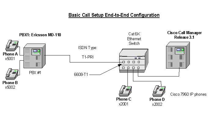
Network Topology
Figure 1 Network Topology or Test Setup
Limitations
Calling Name and Number Feature
•
Calling Name delivery and presentation features are not supported by the Ericsson MD-110 PBX.
•
•
System Components
Cisco Hardware and Software Requirements
•
•
PBX Hardware and Software Requirements
•
•
Features
Calling/Called Number
Configuration
Configuration Sequence and Tasks
Configure in the following sequence:
Step 1.
Setup internal characteristics for the route. Ex. Traffic direction, services, Bearer capabilities.<_ROCAP:ROU=20;ROUTE CATEGORY DATAROU SEL TRM SERV NODG DIST DISL TRAF SIG BCAP20 711000000000 7 3110000010 0 5 20 03151515 211100000031 111111ENDStep 2.
<_RODAP:ROU=20;ROUTE DATAROU TYPE VARC VARI VARO FILTER20 SL63 H'00001110 H'00000002 H'00000037 NOENDT1-PRI Route Protocol Characteristics, protocol side "User"<_RODAP:ROU=20;ROUTE DATAROU TYPE VARC VARI VARO FILTER20 SL63 H'00001110 H'00000002 H'00000027 NOENDStep 3.
T1-PRI trunk lines (B-channels)<_ROEDP:ROU=20,TRU=ALL;ROUTE EQUIPMENT DATAROU TRU EQU SQU INDDAT20 001-1 001-0-00-00 0-00-3 H'00000000000020 001-2 001-0-00-01 0-00-3 H'00000000000020 001-3 001-0-00-02 0-00-3 H'00000000000020 001-4 001-0-00-03 0-00-3 H'00000000000020 001-5 001-0-00-04 0-00-3 H'00000000000020 001-6 001-0-00-05 0-00-3 H'00000000000020 001-7 001-0-00-06 0-00-3 H'00000000000020 001-8 001-0-00-07 0-00-3 H'00000000000020 001-9 001-0-00-08 0-00-3 H'00000000000020 001-10 001-0-00-09 0-00-3 H'00000000000020 001-11 001-0-00-10 0-00-3 H'00000000000020 001-12 001-0-00-11 0-00-3 H'00000000000020 001-13 001-0-00-12 0-00-3 H'00000000000020 001-14 001-0-00-13 0-00-3 H'00000000000020 001-15 001-0-00-14 0-00-3 H'00000000000020 001-16 001-0-00-15 0-00-3 H'00000000000020 001-17 001-0-00-16 0-00-3 H'00000000000020 001-18 001-0-00-17 0-00-3 H'00000000000020 001-19 001-0-00-18 0-00-3 H'00000000000020 001-20 001-0-00-19 0-00-3 H'00000000000020 001-21 001-0-00-20 0-00-3 H'00000000000020 001-22 001-0-00-21 0-00-3 H'00000000000020 001-23 001-0-00-22 0-00-3 H'000000000000ENDStep 4.
Route and Access Code for the trunk Information- Note PRI uses Route 20<_RODDP:DEST=ALL;EXTERNAL DESTINATION ROUTE DATADEST DRN ROU CHO CUST ADC TRC SRT NUMACK PRE2 20 100500000000025000 0 1 030 1 100500000000025000 0 3 031 2 100500000000025000 0 3 032 3 100500000000025000 0 3 033 4 100500000000025000 0 3 034 5 100500000000025000 0 3 035 6 000500000000025000 0 3 036 7 000500000000025000 0 3 037 8 000500000000025000 0 3 039 21 100500000000025000 0 3 040 11 100500000000025000 0 3 041 12 000500000000025000 0 3 042 13 000500000000025000 0 3 0END
Note:
Configuration Menus and Commands
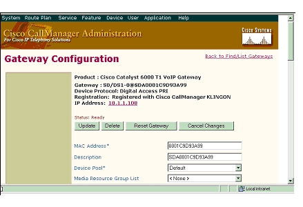
Configuring the Cisco Call Manager
Figure 2 6608 Gateway Configuration
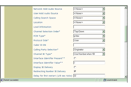
Figure 3
6608 Gateway Configuration, cont.
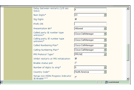
Figure 4 More 6608 Gateway Configuration
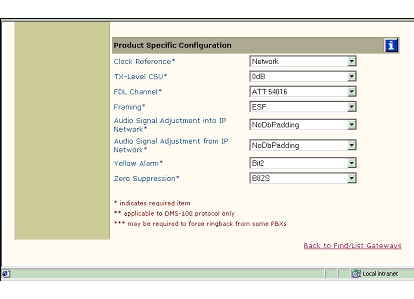
Figure 5
6608 Gateway Configuration - Product Specific Configuration
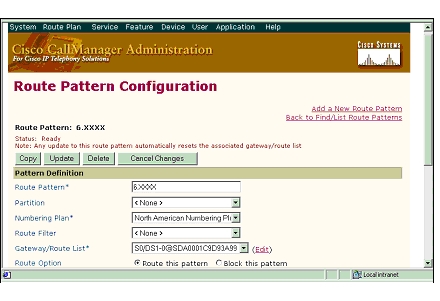
Figure 6 Route Pattern Configuration
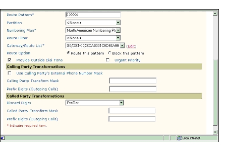
Figure 7 Route Pattern Configuration, Cont.
Test Configuration
As shown in Figure 8 below, an Ericsson MD-110 PBX was connected via an ISDN T1 PRI link to a Cisco 6608-E1 Gateway, which in turn, was connected to an Ethernet switch. The interoperability testing involved Layers 1, 2 and 3 on the ISDN PRI link between a Cisco 6608-T1 and the PBX.
Figure 8 Test Configuration
Layer 1 (Physical Layer)
The Ericsson MD-110 uses a command line interface which allows you to change many switch features with a single command. The PBX documentation must be consulted to make changes. Physical layer parameters (along with many other features) are controlled by using RODAI command.
Layers 2 & 3 (Q.921 and Q.931)
Layer 2 and 3 packet exchanges were monitored using an Acacia Clarinet protocol analyzer, bridged across the PRI link in high impedance mode.
Layer 2 Q.921 packets were monitored to ensure that each PBX/6608-T1 software configuration properly exchanged SABME/UA packets to initialize the ISDN link, and then RR packets were exchanged every 30 seconds.
Layer 3 Q.931 packets were monitored to ensure that the appropriate call setup/teardown packets were exchanged for each configuration, and that the SETUP packets contained the mandatory Information Elements (IE) with the necessary details, as well as optional IEs such as Calling Name and Number.
Telephone calls were made end-to-end in both directions through the Cisco 6608-T1 Gateway. A check was made to ensure that there was an audio path in both directions for each call.
User/Network Settings
The Cisco 6608-T1 Gateway with ISDN protocol type setting of PRI-NI2 supports both protocol sides by selecting "Network/User" in the protocol side field when configuring the Gateway via CallManager.
The Ericsson MD-110, supports both "USER" (peer-slave) and "NETWORK" (peer-master) protocol sides by using RODAI command.
Test Results
Testing was performed by Test Engineer(s): Samir Batio, September 26, 2001
PBX1 configured as National ISDN, emulate Network and Cisco 6608-T1 Gateway configured as PRI NI2, emulate User.
National ISDN/Network
PRI NI2/User
)
Phone A to Phone C
Yes
Yes
No
No1
No
Phone C to Phone A
Yes
Yes
No
Yes
No
1 CallManager is not sending "Connected Number" information in the connect message back to PBX.
2 Calling Name delivery and presentation features are not supported by the Ericsson ISDN PRI Link.
Call Transfers: (Supervised Local Transfers)
Call Conferencing (Local)
Call Forward (Local)
Appendix
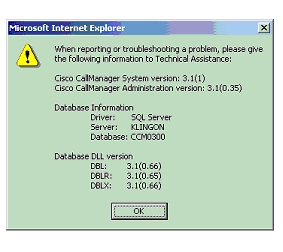
Figure 9 CallManager Software Release:
Ericsson MD-110 Software Version
<_CADAP;CALENDAR DATAIDENTITY=DANDS-EURO-TESTVERSION=ASB50104-R6-SES-R9-BC90D/CNI80CALENDAR TIME NOT VALID16:28:45TUE 11 SEP 2001ENDCatalyst 6000 Switch Configuration
Console> (enable) sh versionWS-C6006 Software, Version NmpSW: 5.5(6a)Copyright (c) 1995-2001 by Cisco SystemsNMP S/W compiled on Feb 23 2001, 10:23:18System Bootstrap Version: 5.3(1)Hardware Version: 2.0 Model: WS-C6006 Serial #: TBA04511172Mod Port Model Serial # Versions--- ---- ------------------- ----------- --------------------------------------1 2 WS-X6K-SUP1A-2GE SAD05010NBK Hw : 7.0Fw : 5.3(1)Fw1: 5.4(2)Sw : 5.5(6a)Sw1: 5.5(6a)WS-F6K-PFC SAD05020221 Hw : 1.13 48 WS-X6348-RJ-45 SAD04420N7B Hw : 1.4Fw : 5.4(2)Sw : 5.5(6a)WS-F6K-VPWR Hw : 1.04 24 WS-X6624-FXS SAD050203M8 Hw : 3.0Fw : 5.4(2)Sw : 5.5(6a)HP : A00203010010; DSP : A003E031 (3.3.32)5 8 WS-X6608-T1 SAD04400EM0 Hw : 1.1Fw : 5.4(2)Sw : 5.5(6a)HP1: D00403010017; DSP1: D005E031 (3.3.32)HP2: D00403010017; DSP2: D005E031 (3.3.32)HP3: D00403010017; DSP3: D005E031 (3.3.32)HP4: D00403010017; DSP4: D005E031 (3.3.32)HP5: D00403010017; DSP5: D005E031 (3.3.32)HP6: D00403010017; DSP6: D005E031 (3.3.32)HP7: D00403010017; DSP7: D005E031 (3.3.32)HP8: D00403010017; DSP8: D005E031 (3.3.32)6 8 WS-X6608-E1 SAD04380DW1 Hw : 1.1Fw : 5.4(2)Sw : 5.5(6a)HP1: D00403010017; DSP1: D005E031 (3.3.32)HP2: D00403010017; DSP2: D005E031 (3.3.32)HP3: D00403010017; DSP3: D005E031 (3.3.32)HP4: D00403010017; DSP4: D005E031 (3.3.32)HP5: D00403010017; DSP5: D005E031 (3.3.32)HP6: D00403010017; DSP6: D005E031 (3.3.32)HP7: D00403010017; DSP7: D005E031 (3.3.32)HP8: D00403010017; DSP8: D005E031 (3.3.32)DRAM FLASH NVRAMModule Total Used Free Total Used Free Total Used Free------ ------- ------- ------- ------- ------- ------- ----- ----- -----1 65408K 37863K 27545K 16384K 11546K 4838K 512K 198K 314KUptime is 83 days, 2 hours, 34 minutesConsole> (enable)______________________________________________________________________________Console> (enable) sh moduleMod Slot Ports Module-Type Model Sub Status--- ---- ----- ------------------------- ------------------- --- --------1 1 2 1000BaseX Supervisor WS-X6K-SUP1A-2GE yes ok3 3 48 10/100BaseTX Ethernet WS-X6348-RJ-45 yes ok4 4 24 FXS WS-X6624-FXS no ok5 5 8 T1 WS-X6608-T1 no ok6 6 8 E1 WS-X6608-E1 no okMod Module-Name Serial-Num--- ------------------- -----------1 SAD05010NBK3 SAD04420N7B4 SAD050203M85 SAD04400EM06 SAD04380DW1Mod MAC-Address(es) Hw Fw Sw--- -------------------------------------- ------ ---------- -----------------1 00-04-c0-f8-42-02 to 00-04-c0-f8-42-03 7.0 5.3(1) 5.5(6a)00-04-c0-f8-42-00 to 00-04-c0-f8-42-0100-04-9b-f0-78-00 to 00-04-9b-f0-7b-ff3 00-02-fc-20-5e-50 to 00-02-fc-20-5e-7f 1.4 5.4(2) 5.5(6a)4 00-03-32-ba-2e-35 3.0 5.4(2) 5.5(6a)5 00-01-c9-d9-3a-98 to 00-01-c9-d9-3a-9f 1.1 5.4(2) 5.5(6a)6 00-01-c9-d8-63-3e to 00-01-c9-d8-63-45 1.1 5.4(2) 5.5(6a)Mod Sub-Type Sub-Model Sub-Serial Sub-Hw--- ----------------------- ------------------- ----------- ------1 L3 Switching Engine WS-F6K-PFC SAD05020221 1.13 Inline Power Module WS-F6K-VPWR 1.0Console> (enable)______________________________________________________________________________Console> (enable) sh port 5Port Name Status Vlan Duplex Speed Type----- ------------------ ---------- ---------- ------ ----- ------------5/1 notconnect 1 full 1.544 T15/2 connected 1 full 1.544 T15/3 notconnect 1 full 1.544 T15/4 notconnect 1 full 1.544 T15/5 notconnect 1 full 1.544 T15/6 notconnect 1 full 1.544 T15/7 notconnect 1 full 1.544 T15/8 notconnect 1 full 1.544 T1Port DHCP MAC-Address IP-Address Subnet-Mask-------- ------- ----------------- --------------- ---------------5/1 enable 00-01-c9-d9-3a-98 10.1.1.107 255.255.255.05/2 enable 00-01-c9-d9-3a-99 10.1.1.108 255.255.255.05/3 enable 00-01-c9-d9-3a-9a 10.1.1.109 255.255.255.05/4 enable 00-01-c9-d9-3a-9b 10.1.1.110 255.255.255.05/5 enable 00-01-c9-d9-3a-9c 10.1.1.111 255.255.255.05/6 enable 00-01-c9-d9-3a-9d 10.1.1.112 255.255.255.05/7 enable 00-01-c9-d9-3a-9e 10.1.1.113 255.255.255.05/8 enable 00-01-c9-d9-3a-9f 10.1.1.114 255.255.255.0Port Call-Manager(s) DHCP-Server TFTP-Server Gateway-------- ----------------- --------------- --------------- ---------------5/1 10.1.1.2 10.1.1.2 10.1.1.2 10.1.1.75/2 10.1.1.2 10.1.1.2 10.1.1.2 10.1.1.75/3 10.1.1.2 10.1.1.2 10.1.1.2 10.1.1.75/4 10.1.1.2 10.1.1.2 10.1.1.2 10.1.1.75/5 10.1.1.2 10.1.1.2 10.1.1.2 10.1.1.75/6 10.1.1.2 10.1.1.2 10.1.1.2 10.1.1.75/7 10.1.1.2 10.1.1.2 10.1.1.2 10.1.1.75/8 10.1.1.2 10.1.1.2 10.1.1.2 10.1.1.7Port DNS-Server(s) Domain-------- ----------------- -------------------------------------------------5/1 - -5/2 - -5/3 - -5/4 - -5/5 - -5/6 - -5/7 - -5/8 - -Port CallManagerState DSP-Type-------- ---------------- --------5/1 registered C5495/2 registered C5495/3 registered C5495/4 registered C5495/5 registered C5495/6 registered C5495/7 registered C5495/8 registered C549Port NoiseRegen NonLinearProcessing----- ---------- -------------------5/1 enabled enabled5/2 enabled enabled5/3 enabled enabled5/4 enabled enabled5/5 enabled enabled5/6 enabled enabled5/7 enabled enabled5/8 enabled enabledConsole> (enable)
![]()
![]()
![]()
![]()
![]()
![]()
![]()
![]()
Posted: Fri Sep 7 00:26:00 PDT 2007
All contents are Copyright © 1992--2007 Cisco Systems, Inc. All rights reserved.
Important Notices and Privacy Statement.