|
|

Table Of Contents
Cisco Systems Equipment Needed
Configuring the Nortel Meridian Opt11C PBX
Configure the Common Equipment
Configure the Route Data Block
Configure the Coordinated Dialing Plan
Calling Name and Number Feature
Nortel Meridian Opt11C Software Release
Catalyst 6000 Switch Configuration
Application Note
Nortel Meridian Opt11C Rel 25 PBX with CallManager using the Cisco 6608-T1 PRI DMS-100 Gateway
This application note discusses the integration of the Nortel Meridian Opt11C Rel 25 PBX with CallManager using the Cisco 6608-T1 PRI DMS-100 Gateway.
Integration Description
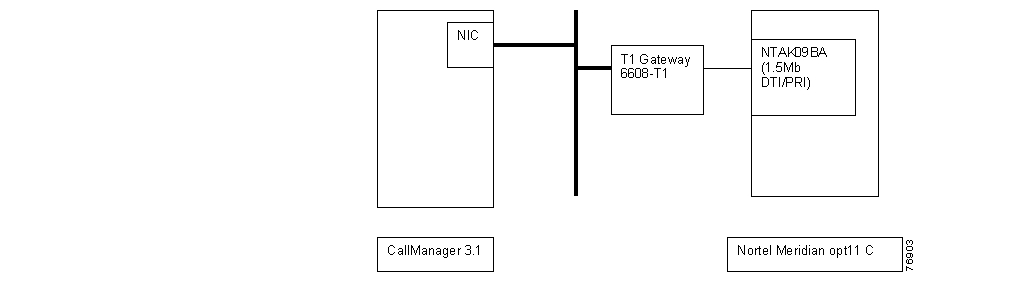
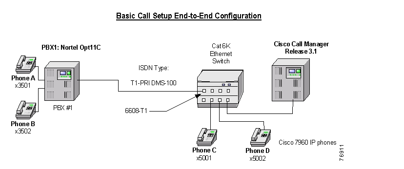
Connectivity is achieved by using the Nortel DMS-100 PRI protocol. The Nortel Meridian Opt11C supports the USER side only when switch type is set to DMS-100. The figure below shows the general network layout for the integration.
Network Layout
Cisco Systems Equipment Needed
•
Hardware (Gateway): Cisco 6608 T1 Port
•
PBX Requirements
•
•
Features
Key features supported:
•
•
Key features not supported:
•
Configuring the Nortel Meridian Opt11C PBX
To configure the Nortel Meridian Opt11C PBX, do the following:
Step 1.
Step 2.
Step 3.
Step 4.
Step 5.
Configure the Common Equipment
The following example shows the configuration of the common equipment.
Common Equipment Configuration
LD 22PT2000MARP NOT ACTIVATEDREQ PRTTYPE CEQUCEQUMPED 8DSUPL 000 004 008 012016 032 036 040044 048 064 068072XCT 000CONF 029 030 031 062094 095DLOP NUM DCH FRM LCMT YALM T1TE TRSHPRI 004 23 ESF B8S FDL - 00005 23 ESF B8S FDL - 00MISPREQ ****Configure the D-Channel
The following example shows the configuration of the D-channel.
D-channel Configuration
>LD 22PT2000MARP NOT ACTIVATEDREQ PRTTYPE ADAN DCH 5ADAN DCH 5CTYP MSDLCARD 05PORT 1DES DMS-100USR PRIDCHL 5OTBF 32PARM RS422 DTEDRAT 64KCCLOK EXTIFC D100SIDE USRCNEG 1RLS ID **RCAP ND2MBGA NOOVLR NOOVLS NOT200 3T203 10N200 3N201 260K 7REQ ****Configure the Route Data Block
The following example shows the configuration of the Route Data Block.
Route Data Block Configuration
>LD 21PT1000REQ: PRTTYPE: RDBCUST 0ROUT 105TYPE RDBCUST 00DMODROUT 105DES DMS-100TKTP TIENPID_TBL_NUM 0ESN NOCNVT NOSAT NORCLS EXTDTRK YESBRIP NODGTP PRIISDN YESMODE PRAIFC D100SBN NOPNI 00000NCNA YESNCRD NOCHTY BCHCTYP UKWNINAC NOISAR NOCPUB OFFDAPC NOBCOT 0DSEL VODPTYP PRIAUTO NODNIS NODCDR NOICOG IAOSRCH RRBTRMB YESSTEPACOD 705TCPP NOPII NOTARG 01CLEN 1BILN NOOABSINSTANTKSIGO STDICIS YESTIMR ICF 512OGF 512EOD 13952NRD 10112DDL 70ODT 4096RGV 640GRD 896SFB 3NBS 2048NBL 4096TFD 0DRNG NOCDR NOMUS NOPAGE 002OHQ NOOHQT 00CBQ NOAUTH NOTTBL 0PLEV 2ALRM NOART 0SGRP 0AACR NOREQ: ****Configure the Trunk
The following example shows the configuration of the trunk.
Trunk Configuration
>ld 20PT0000MARP NOT ACTIVATEDREQ: PRTTYPE: TNBTN 5 1DATEPAGEDESTN 005 01TYPE TIECDEN SDCUST 0TRK PRIPDCA 1PCML MUNCOS 0RTMB 105 1B-CHANNEL SIGNALINGTGAR 1AST NOIAPG 0CLS UNR DTN CND WTA LPR APN THFD HKDP10 VNLTKIDDATE 13 MAR 2001NACT ****Configure the Coordinated Dialing Plan
The following example shows the configuration of the coordinated dialing plan.
Coordinated Dialing Plan Configuration
>LD 87ESN000MEM AVAIL: (U/P): 1302848 USED U P: 62313 27478 TOT: 1392639DISK RECS AVAIL: 491REQ PRTCUST 0FEAT CDPTYPE DSCDSC 50DSC 50FLEN 0DSP LSCRLI 5NPANXXMEM AVAIL: (U/P): 1302848 USED U P: 62313 27478 TOT: 1392639DISK RECS AVAIL: 491REQ ****>OVL000>LD 86ESN000MEM AVAIL: (U/P): 1302848 USED U P: 62313 27478 TOT: 1392639DISK RECS AVAIL: 491REQ PRTCUST 0FEAT RLBRLI 5RLI 5ENTR 0LTER NOROUT 105TOD 0 ON 1 ON 2 ON 3 ON4 ON 5 ON 6 ON 7 ONCNV NOEXP NOFRL 0DMI 0FCI 0FSNI 0SBOC NRROHQ NOCBQ NOISET 0NALT 5MFRL 0OVLL 0MEM AVAIL: (U/P): 1302848 USED U P: 62313 27478 TOT: 1392639DISK RECS AVAIL: 491REQDTC103****Configuring Cisco CallManager
To configure Cisco CallManager, do the following:
Step 1.
Step 2.
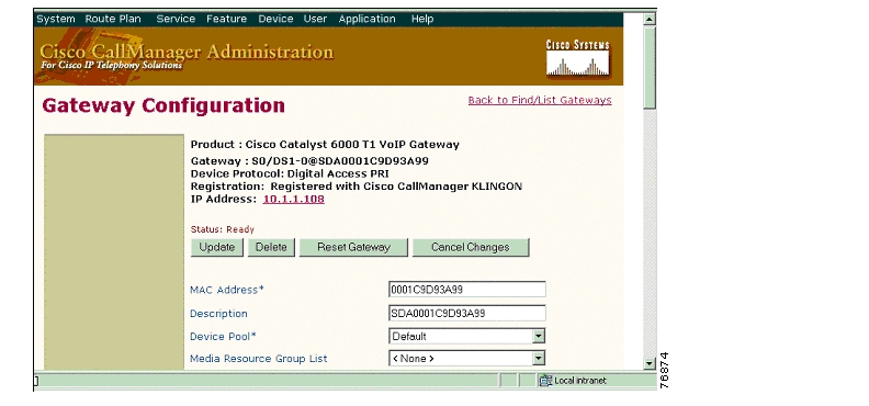
Gateway Configuration
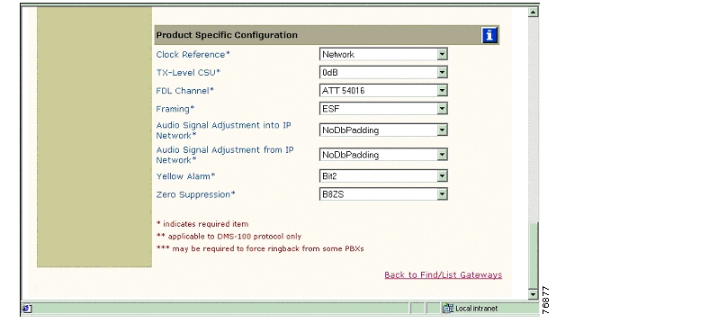
The following figures show the configuration of the Cisco 6608 Gateway.
Cisco 6608 Gateway Configuration
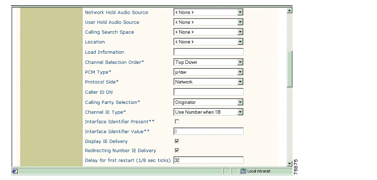
Cisco 6608 Gateway Configuration Continued
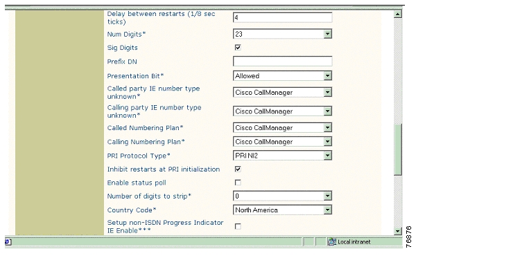
Cisco 6608 Gateway Configuration Continued
Cisco 6608 Gateway Configuration Continued
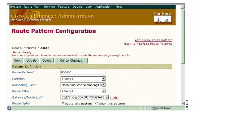
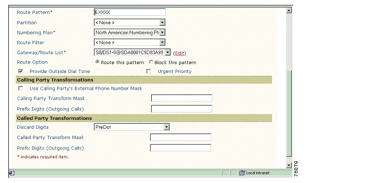
Route Pattern Configuration
The following figures show the configuration of the route pattern.
Route Pattern Configuration
Route Pattern Configuration Continued
Considerations
Calling Name and Number Feature
Calling Name delivery and presentation features are supported by the Nortel PBX as of Release 25 for DMS-100 switch-type.
The Nortel Meridian Opt11C supports the USER side only when the switch type is set to DMS-100. Therefore, the Cisco 6608 Gateway should be configured to emulate the NETWORK side.
When calling from a Cisco 7960 IP phone to a Nortel digital phone, the Calling/Called Name and Number are displayed on both phones after the call is answered as expected.
When calling from a Nortel digital phone to a Cisco 7960 IP phone, the IP phone displays the Connected Name and Number after the call is answered. The Nortel phone, however, is not updated when the call is answered. It displays the numbers being dialed instead. (the access code and the extension number). It was verified using ISDN protocol analyzer that the CallManager was not sending the Connected Number information in the connect message back to PBX.
Integration Testing
This section contains information about the setup used in testing the integration of the Nortel Meridian Opt11C Release 25 PBX and the Cisco 6608-T1 PRI DMS-100 Gateway.
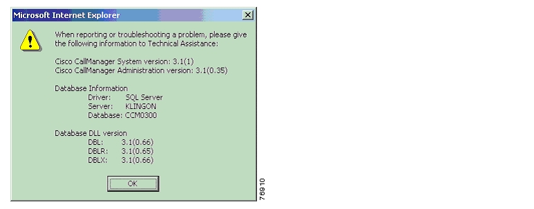
CallManager Software Release:
The following figure shows the information about the release of CallManager being used.
CallManager Software Release
Nortel Meridian Opt11C Software Release
The following provides information about the release of the Nortel Meridian Opt11C used.
Software Release
>LD 22PT2000MARP NOT ACTIVATEDREQ ISSVERSION 2111RELEASE 25ISSUE 15 +PSWV VERSION: PSWV 33REQDTC103****Software Packages Installed (Release 25)
>LD 22PT2000MARP NOT ACTIVATEDREQ PRTTYPE PKGOPTF 1CUST 2CDR 4CTY 5RAN 7TAD 8DNDI 9EES 10INTR 11ANI 12ANIR 13BRTE 14DNDG 16MSB 17SS25 18DDSP 19ODAS 20DI 21CHG 23CAB 24BAUT 25CASM 26CASR 27BQUE 28NTRF 29NCOS 32CPRK 33SSC 34IMS 35UST 35UMG 35ROA 36NSIG 37MCBQ 38NSC 39BACD 40ACDB 41ACDC 42LMAN 43MUS 44ACDA 45MWC 46AAB 47GRP 48NFCR 49ACDD 50LNK 51FCA 52SR 53AA 54HIST 55AOP 56BARS 57NARS 58CDP 59PQUE 60FCBQ 61OHQ 62NAUT 63SNR 64PAGE 001NXFR 67HOT 70DHLD 71LSEL 72SS5 73DRNG 74PBXI 75DLDN 76CSL 77OOD 79SCI 80CCOS 81CDRQ 83TENS 86FTDS 87DSET 88TSET 89LNR 90DLT2 91PXLT 92SUPV 93CPND 95DNIS 98BGD 99RMS 100MR 101AWU 102PMSI 103LLC 105MCT 107ICDR 108APL 109TVS 110TOF 111IDC 113AUXS 114DCP 115PAGT 116CBC 117CCDR 118EMUS 119SCMP 121FTC 125BKI 127DTI2 129TBAR 132ENS 133FFC 139DCON 140MPO 141ISDN 145PRA 146ISL 147NTWK 148IEC 149DNXP 150CDRE 151IAP3P 153PRI2 154ACNT 155THF 157PAGE 002FGD 158FNP 160ISDN INTL SUP 161SAR 162LAPW 164GPRI 167ARIE 170CPGS 172ECCS 173AAA 174NMS 175EOVF 178HVS 179DKS 180SACP 181OVLP 184EDRG 185POVR 186SECL 191ORC-RVQ 192AINS 200IPRA 202XPE 203XCT0 204XCT1 205MLWU 206NACD 207HSE 208MLM 209MAID 210VAWU 212EAR 214ECT 215BRI 216IVR 218MWI 219MSDL 222FC68 223M911 224CWNT 225SSAU 229BRIT 233FCDR 234BRIL 235MCMO 240MULTI_USER 242ALRM_FILTER 243VMBA 246CALL ID 247M911 ENH 249DPNA 250SCDR 251ARFW 253PHTN 254ADMINSET 256ATX 258QSIG 263NI-2 291MAT 296MQA 297CPP 301PAGE 003QSIGGF 305CPRKNET 306PAGENET 307CPCI 310NGCC 311TATO 312TATO 312QSIG-SS 316QTN 321NGEN 324RANBRD 327MUSBRD 328ESA 329ESA_SUPP 330ESA_CLMP 331CNUMB 332CNAME 333NI-2 CBC 334MEET 348MC32 350DBA 351FDID 362NMCE 364STS_MSG 380CDIR 381VIRTUAL_OFFICE 382REQ ****>OVL000Catalyst 6000 Switch Configuration
The following shows the configuration of the Catalyst 6000 Switch.
Console> (enable) show versionWS-C6006 Software, Version NmpSW: 5.5(6a)Copyright (c) 1995-2001 by Cisco SystemsNMP S/W compiled on Feb 23 2001, 10:23:18System Bootstrap Version: 5.3(1)Hardware Version: 2.0 Model: WS-C6006 Serial #: TBA04511172Mod Port Model Serial # Versions--- ---- ------------------- ----------- --------------------------------------1 2 WS-X6K-SUP1A-2GE SAD05010NBK Hw : 7.0Fw : 5.3(1)Fw1: 5.4(2)Sw : 5.5(6a)Sw1: 5.5(6a)WS-F6K-PFC SAD05020221 Hw : 1.13 48 WS-X6348-RJ-45 SAD04420N7B Hw : 1.4Fw : 5.4(2)Sw : 5.5(6a)WS-F6K-VPWR Hw : 1.04 24 WS-X6624-FXS SAD050203M8 Hw : 3.0Fw : 5.4(2)Sw : 5.5(6a)HP : A00203010010; DSP : A003E031 (3.3.32)5 8 WS-X6608-T1 SAD04400EM0 Hw : 1.1Fw : 5.4(2)Sw : 5.5(6a)HP1: D00403010017; DSP1: D005E031 (3.3.32)HP2: D00403010017; DSP2: D005E031 (3.3.32)HP3: D00403010017; DSP3: D005E031 (3.3.32)HP4: D00403010017; DSP4: D005E031 (3.3.32)HP5: D00403010017; DSP5: D005E031 (3.3.32)HP6: D00403010017; DSP6: D005E031 (3.3.32)HP7: D00403010017; DSP7: D005E031 (3.3.32)HP8: D00403010017; DSP8: D005E031 (3.3.32)6 8 WS-X6608-E1 SAD04380DW1 Hw : 1.1Fw : 5.4(2)Sw : 5.5(6a)HP1: D00403010017; DSP1: D005E031 (3.3.32)HP2: D00403010017; DSP2: D005E031 (3.3.32)HP3: D00403010017; DSP3: D005E031 (3.3.32)HP4: D00403010017; DSP4: D005E031 (3.3.32)HP5: D00403010017; DSP5: D005E031 (3.3.32)HP6: D00403010017; DSP6: D005E031 (3.3.32)HP7: D00403010017; DSP7: D005E031 (3.3.32)HP8: D00403010017; DSP8: D005E031 (3.3.32)DRAM FLASH NVRAMModule Total Used Free Total Used Free Total Used Free------ ------- ------- ------- ------- ------- ------- ----- ----- -----1 65408K 37863K 27545K 16384K 11546K 4838K 512K 198K 314KUptime is 83 days, 2 hours, 34 minutesConsole> (enable)______________________________________________________________________________Console> (enable) show moduleMod Slot Ports Module-Type Model Sub Status--- ---- ----- ------------------------- ------------------- --- --------1 1 2 1000BaseX Supervisor WS-X6K-SUP1A-2GE yes ok3 3 48 10/100BaseTX Ethernet WS-X6348-RJ-45 yes ok4 4 24 FXS WS-X6624-FXS no ok5 5 8 T1 WS-X6608-T1 no ok6 6 8 E1 WS-X6608-E1 no okMod Module-Name Serial-Num--- ------------------- -----------1 SAD05010NBK3 SAD04420N7B4 SAD050203M85 SAD04400EM06 SAD04380DW1Mod MAC-Address(es) Hw Fw Sw--- -------------------------------------- ------ ---------- -----------------1 00-04-c0-f8-42-02 to 00-04-c0-f8-42-03 7.0 5.3(1) 5.5(6a)00-04-c0-f8-42-00 to 00-04-c0-f8-42-0100-04-9b-f0-78-00 to 00-04-9b-f0-7b-ff3 00-02-fc-20-5e-50 to 00-02-fc-20-5e-7f 1.4 5.4(2) 5.5(6a)4 00-03-32-ba-2e-35 3.0 5.4(2) 5.5(6a)5 00-01-c9-d9-3a-98 to 00-01-c9-d9-3a-9f 1.1 5.4(2) 5.5(6a)6 00-01-c9-d8-63-3e to 00-01-c9-d8-63-45 1.1 5.4(2) 5.5(6a)Mod Sub-Type Sub-Model Sub-Serial Sub-Hw--- ----------------------- ------------------- ----------- ------1 L3 Switching Engine WS-F6K-PFC SAD05020221 1.13 Inline Power Module WS-F6K-VPWR 1.0Console> (enable)______________________________________________________________________________Console> (enable) show port 5Port Name Status Vlan Duplex Speed Type----- ------------------ ---------- ---------- ------ ----- ------------5/1 notconnect 1 full 1.544 T15/2 connected 1 full 1.544 T15/3 notconnect 1 full 1.544 T15/4 notconnect 1 full 1.544 T15/5 notconnect 1 full 1.544 T15/6 notconnect 1 full 1.544 T15/7 notconnect 1 full 1.544 T15/8 notconnect 1 full 1.544 T1Port DHCP MAC-Address IP-Address Subnet-Mask-------- ------- ----------------- --------------- ---------------5/1 enable 00-01-c9-d9-3a-98 10.1.1.107 255.255.255.05/2 enable 00-01-c9-d9-3a-99 10.1.1.108 255.255.255.05/3 enable 00-01-c9-d9-3a-9a 10.1.1.109 255.255.255.05/4 enable 00-01-c9-d9-3a-9b 10.1.1.110 255.255.255.05/5 enable 00-01-c9-d9-3a-9c 10.1.1.111 255.255.255.05/6 enable 00-01-c9-d9-3a-9d 10.1.1.112 255.255.255.05/7 enable 00-01-c9-d9-3a-9e 10.1.1.113 255.255.255.05/8 enable 00-01-c9-d9-3a-9f 10.1.1.114 255.255.255.0Port Call-Manager(s) DHCP-Server TFTP-Server Gateway-------- ----------------- --------------- --------------- ---------------5/1 10.1.1.2 10.1.1.2 10.1.1.2 10.1.1.75/2 10.1.1.2 10.1.1.2 10.1.1.2 10.1.1.75/3 10.1.1.2 10.1.1.2 10.1.1.2 10.1.1.75/4 10.1.1.2 10.1.1.2 10.1.1.2 10.1.1.75/5 10.1.1.2 10.1.1.2 10.1.1.2 10.1.1.75/6 10.1.1.2 10.1.1.2 10.1.1.2 10.1.1.75/7 10.1.1.2 10.1.1.2 10.1.1.2 10.1.1.75/8 10.1.1.2 10.1.1.2 10.1.1.2 10.1.1.7Port DNS-Server(s) Domain-------- ----------------- -------------------------------------------------5/1 - -5/2 - -5/3 - -5/4 - -5/5 - -5/6 - -5/7 - -5/8 - -Port CallManagerState DSP-Type-------- ---------------- --------5/1 registered C5495/2 registered C5495/3 registered C5495/4 registered C5495/5 registered C5495/6 registered C5495/7 registered C5495/8 registered C549Port NoiseRegen NonLinearProcessing----- ---------- -------------------5/1 enabled enabled5/2 enabled enabled5/3 enabled enabled5/4 enabled enabled5/5 enabled enabled5/6 enabled enabled5/7 enabled enabled5/8 enabled enabledConsole> (enable)Test Configuration
The following figure represents the various configurations used for testing.
Testbed Network Configuration
As shown in the figure above, a Nortel Meridian Opt 11C PBX was connected via an ISDN T1 PRI link to a Cisco 6608-T1 Gateway, which in turn, was connected to an Ethernet switch. The interoperability testing involved Layers 1, 2 and 3 on the ISDN PRI link between a Cisco 6608-T1 and the PBX.
Layer 1 (Physical Layer)
The Nortel configuration screen for the T1 trunk interface is reached using LD 17, setting the CEQU (Common Equipment parameters).
Layers 2 & 3 (Q.921 and Q.931)
Layer 2 and 3 packet exchanges were monitored using an Acacia Clarinet protocol analyzer, bridged across the PRI link in high impedance mode.
Layer 2 Q.921 packets were monitored to ensure that each PBX/2621 software configuration properly exchanged SABME/UA packets to initialize the ISDN link, and then RR packets were exchanged every 30 seconds.
Layer 3 Q.931 packets were monitored to ensure that the appropriate call setup/teardown packets were exchanged for each configuration, and that the SETUP packets contained the mandatory Information Elements with the necessary details, as well as optional IEs such as Calling Name and Number.
Telephone calls were made end-to-end in both directions through the Cisco 6608-T1 Gateway, and a check was made to ensure that there was an audio path in both directions for each call.
User/Network Settings
The Cisco 6608-T1 Gateway with ISDN protocol type setting of PRI DMS-100 supports both protocol sides by selecting "Network/User" in the protocol side field when configuring the Gateway via CallManager.
The Nortel Meridian Opt11C supports the USER side only when the switch type is set to DMS-100. Therefore, the Cisco 6608 Gateway should be configured to emulate the NETWORK side. This USER choice is set on the Nortel by using LD 17.
Test Results
Testing was performed by Test Engineer(s): Samir Batio, September 11, 2001
Test 1
In test 1:
•
•
The results are shown in the following tables.
Table 1 Basic Calls (Enbloc Sending)
Phone A to Phone C
Yes
Yes
Yes
No 1
No2
Phone C to Phone A
Yes
Yes
Yes
Yes
Yes
1 CallManager is not sending the Connected Number information in the CONNECT message back to PBX.
2 CallManager is sending the Connected Name (IE Display) information in the CONNECT message but Nortel does not show it on the phone display.
![]()
![]()
![]()
![]()
![]()
![]()
![]()
![]()
Posted: Thu Sep 6 11:29:28 PDT 2007
All contents are Copyright © 1992--2007 Cisco Systems, Inc. All rights reserved.
Important Notices and Privacy Statement.