|
|

Table Of Contents
Configuring the Fujitsu F9600ES PBX
ARS Code, ARS Routes, ARS Dial Plan
Cisco CallManager Configuration
Calling Name and Number feature
Calling Name Display on Fujitsu
Cisco CallManager Software Release
Fujitsu F9600ES Software release
Catalyst 6000 Switch Configuration
Application Note
Fujitsu F9600ES PBX with CallManager using 6608-T1 PRI DMS-100 Gateway
This application note illustrates connectivity for Fujitsu F9600ES PBX with CallManager using 6608-T1 PRI DMS-100 Gateway.
Integration Description
Connectivity is achieved by using the Fujitsu DMS-100 PRI protocol. The Fujitsu F9600ES can be configured as either NETWORK or USER side.
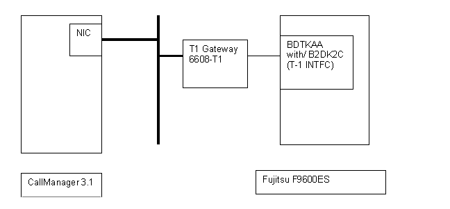
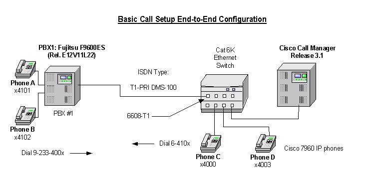
The network topology diagram presented in Figure 1 illustrates the test set-up.
System Components
Cisco Systems equipment:
•
Hardware (Gateway): 6608 T1 Port
•
PBX hardware and software requirements:
•
–
–
•
Feature
Key features supported:
•
•
•
Key features not supported:
•
Network Diagram
Figure 1
Network Test Topology
Configuring the Fujitsu F9600ES PBX
Configure in the following sequence:
1.
2.
5.
6.
7.
Configure ISDN Trunk
DIS ISTRK,,00002000,00002024 (To Display ISDN Trunk Group)# ISDN TRUNK ASSIGNMENT LIST # 01-12-18 TUE 11:31 PAGE-001TNN TGN EN MS PRTCL QDID FNA SUBDID DID UNA RSS RSASGUSPID TID0 170 00002000 1 60 171 00002002 - - ALL ALL - - -0 171 00002003 - - ALL ALL - - -0 171 00002004 - - ALL ALL - - -0 171 00002005 - - ALL ALL - - -0 171 00002006 - - ALL ALL - - -0 171 00002007 - - ALL ALL - - -0 171 00002008 - - ALL ALL - - -0 171 00002009 - - ALL ALL - - -0 171 00002010 - - ALL ALL - - -0 171 00002011 - - ALL ALL - - -0 171 00002012 - - ALL ALL - - -0 171 00002013 - - ALL ALL - - -0 171 00002014 - - ALL ALL - - -0 171 00002015 - - ALL ALL - - -0 171 00002016 - - ALL ALL - - -0 171 00002017 - - ALL ALL - - -0 171 00002018 - - ALL ALL - - -0 171 00002019 - - ALL ALL - - -0 171 00002020 - - ALL ALL - - -0 171 00002021 - - ALL ALL - - -0 171 00002022 - - ALL ALL - - -0 171 00002023 - - ALL ALL - - -0 171 00002024 - - ALL ALL - - -END 01-12-18 TUE 11:32 (CISCO LAB ES R13)DIS ISINF,170,171 (To Display Trunk Group Information)# ISDN TRUNK INFORMATION LIST # 01-12-18 TUE 11:32 PAGE-001# ONE-INTERFACE #< D-CHANNEL >TNN TGN EN MS PRTCL0 170 00002000 1 DMS100< B-CHANNEL >TNN TGN EN QDID FNA SUBDID DID UNA RSS RSASG TYP NSF0 171 00002002 - - ALL ALL - - - MUL 00 171 00002003 - - ALL ALL - - - MUL 00 171 00002004 - - ALL ALL - - - MUL 00 171 00002005 - - ALL ALL - - - MUL 00 171 00002006 - - ALL ALL - - - MUL 00 171 00002007 - - ALL ALL - - - MUL 00 171 00002008 - - ALL ALL - - - MUL 00 171 00002009 - - ALL ALL - - - MUL 00 171 00002010 - - ALL ALL - - - MUL 00 171 00002011 - - ALL ALL - - - MUL 00 171 00002012 - - ALL ALL - - - MUL 00 171 00002013 - - ALL ALL - - - MUL 00 171 00002014 - - ALL ALL - - - MUL 00 171 00002015 - - ALL ALL - - - MUL 00 171 00002016 - - ALL ALL - - - MUL 00 171 00002017 - - ALL ALL - - - MUL 00 171 00002018 - - ALL ALL - - - MUL 00 171 00002019 - - ALL ALL - - - MUL 00 171 00002020 - - ALL ALL - - - MUL 00 171 00002021 - - ALL ALL - - - MUL 00 171 00002022 - - ALL ALL - - - MUL 00 171 00002023 - - ALL ALL - - - MUL 00 171 00002024 - - ALL ALL - - - MUL 0< CBC GROUP TGN >PILOT MTGN - NSF MTGN - NSF MTGN - NSF MTGN - NSFNONEEND 01-12-18 TUE 11:32 (CISCO LAB ES R13)Class of Service
DIS COSF,,1,1 (To Display Class of Service Features)# COS CHECK TABLE LIST # 01-12-18 TUE 11:33 PAGE-001TNN COS --------------AVAILABLE FEATURE NUMBER (FNO)---------------0 1 70 71 72 75 76 130 135 138 302 304 318 335 339 348 354355 363 365 398 401 404 415 417 422 440 445 458 459 496 498540 581 591END 01-12-18 TUE 11:33 (CISCO LAB ES R13)Trunk Group
DIS TG,170,171,1 (To Display Trunk Group Information)# TRUNK GROUP DATA LIST # 01-12-18 TUE 11:33 PAGE-001TGN TYP TID TNN SPC AKI COF TLT DGN RGN COS RSM FRL TRS HNT NAMEAKW AKR AKB RGT AOT GRD REL HKS AFT SHK RHK OPR DMFMIN PRE MAK BRK DGT PST PBO PBF COP PGT MIDPAC MBC STG DT IAS DTS ABS DTK OOC NOC PTF TCS TCR TDT VCM OGFCRCNSF NSFFG PRMFF PRMFV CDNFG TON NPI170 5 37 0 4 0 0 0 1 1 1 1 1 0 00 0 0 0 0 0 0 0 0 0 0 00 0 0 0 0 0 0 0 0 0 028 0 0 0 0 0 0 0 0 0 0 0 0 0 00 0 0 0 0 0 0171 5 38 0 5 0 0 0 0 0 1 1 1 0 10 0 0 0 0 0 0 0 0 0 0 00 0 0 0 0 0 0 0 0 0 028 0 0 0 0 0 0 0 0 0 0 0 0 0 00 0 0 0 0 0 0END 01-12-18 TUE 11:33 (CISCO LAB ES R13)Numbering Plan
DIS NP,,1 (To Display Numbering Plan)# NUMBERING PLAN LIST # 01-12-18 TUE 11:33 PAGE-001TTID= 1DIGIT EDL FNO TGN TGX AJC RDD DOC TTN DN SVN0 1 40 03 4 591 191 1 140 4 25 0 2 041 4 25 0 2 070 30 540 171 2 4 071 30 581 181 2 072 6 591 150 2 173 30 581 128 2 074 30 581 129 2 075 30 517 140 2 29 30 301 0 1 0*11 3 72 0 0*20 7 138 0 3 0*21 3 415 0 0*51 3 72 0 0*70 5 398 0 1 0*71 5 398 0 1 0*72 5 398 0 1 0*73 5 398 0 1 0*74 5 398 0 1 0#67 4 401 0 0D3D 7 138 0 3 0D88 30 304 0 3 0END 01-12-18 TUE 11:33 (CISCO LAB ES R13)DIS MLDT,,4101,4102 (To Display Multi-line Digital Stations)# MLDT ASSIGNMENT LIST # 01-12-18 TUE 11:34 PAGE-001DN( EN ) TYPE RSM FRL COS OT USG SPDL PD HSC KABM LA PP RP IP HF TT RB AH PS LT PDNNAME AMPT4101(00080802) 3 1 1 1 0 0 2 3 10 1 1 1 1 1 1 1 1 0 0'MADRAS' 04102(00080804) 3 1 1 1 0 0 0 3 10 1 1 1 1 1 1 1 1 0 0'TIKA MASALA' 0END 01-12-18 TUE 11:34 (CISCO LAB ES R13)Change Service Parameters
DIS SVP,2,116,116 (To enable Calling Line Identification sending to Public ISDN)# SERVICE LIST # 01-12-18 TUE 11:34 PAGE-001TYPE = 2 ( SVSDT )ID-----DATA ID-----DATA ID-----DATA ID-----DATA ID-----DATA116 1END 01-12-18 TUE 11:34 (CISCO LAB ES R13)DIS SVP,2,218,218 (To provide Calling Party Number to Public ISDN)# SERVICE LIST # 01-12-18 TUE 11:34 PAGE-001TYPE = 2 ( SVSDT )ID-----DATA ID-----DATA ID-----DATA ID-----DATA ID-----DATA218 1END 01-12-18 TUE 11:34 (CISCO LAB ES R13)DIS SVP,2,242,242 (To provide ISDN Name Display over Public Network)# SERVICE LIST # 01-12-18 TUE 11:34 PAGE-001TYPE = 2 ( SVSDT )ID-----DATA ID-----DATA ID-----DATA ID-----DATA ID-----DATA242 1END 01-12-18 TUE 11:34 (CISCO LAB ES R13)DIS SVP,2,180,180 (To provide DMS100 Network Name Display)# SERVICE LIST # 01-12-18 TUE 11:34 PAGE-001TYPE = 2 ( SVSDT )ID-----DATA ID-----DATA ID-----DATA ID-----DATA ID-----DATA180 1END 01-12-18 TUE 11:34 (CISCO LAB ES R13)ARS Code, ARS Routes, ARS Dial Plan
DIS ARSC (To Display ARS Code)# ARS CODE NUMBER LIST # 01-12-18 TUE 11:35 PAGE-001CDNID DS---ARSTB DS---ARSTB DS---ARSTBACDN(1) 2 1 3 1 4 15 1 6 1 7 18 1 9 1OCDN(2) 2 2 3 2 4 25 2 6 2 7 28 2 9 2END 01-12-18 TUE 11:35 (CISCO LAB ES R13)DIS ARSR (To Display ARS Routes)# ARS ROUTE TABLE LIST # 01-12-18 TUE 11:35 PAGE-001ARSTB TNN POS TGN FRL PTNNO T0 T1 T2 T3 T4 T5 T6 T7 LARF CMPF(NARSTB) CDNFG TON NPI NAMF2 0 1 171 0 2 * * * * * * * *0 0 0 110 0 1 0 0 0 * * * * * * * *END 01-12-18 TUE 11:35 (CISCO LAB ES R13)DIS ARSDP (To Display ARS Dial Plan)# ARS RDG QADP LIST # 01-12-18 TUE 11:35 PAGE-001ARSDG ARSRG QADP1 0 0CICF OTPF TOTPF IOTPF DFDSLO1 1 1 1 3END 01-12-18 TUE 11:35 (CISCO LAB ES R13)ARS Digit Manipulation
DIS ARSDM (To Display ARS Digit Manipulation)# ARS DIGIT MANIPULATION PATTERN LIST # 01-12-18 TUE 11:35 PAGE-001PTNNO PRDEL --------PRADG------- PSDEL --------PSADG------- ACPOS ADPN SP0 0 0 0 01 0 1 0 0 02 3 0 0 07 0 7 0 0 011 3 0 0 0END 01-12-18 TUE 11:35 (CISCO LAB ES R13)DIS MCLKS (To Display Main Clock Source/Status)# MAIN CLOCK STATUS DISPLAY # 01-12-18 TUE 11:34< OPERATION STATUS >MCLK #0 *IN 0< ALARM STATUS >MCLK #0 NORMALIN 0 TROUBLEEND 01-12-18 TUE 11:34 (CISCO LAB ES R13)
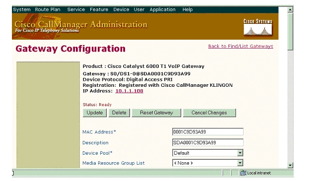
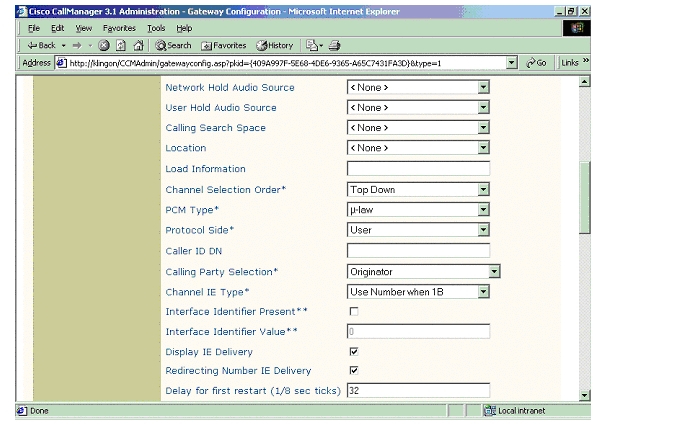
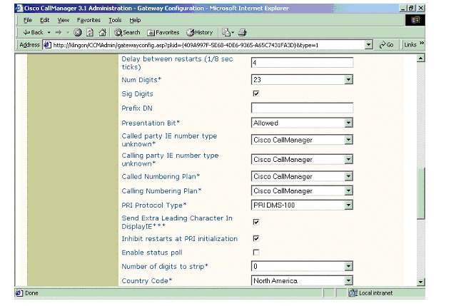
Cisco CallManager Configuration
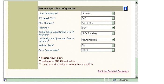
6608-T1 Gateway Configuration
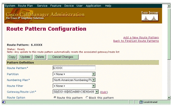
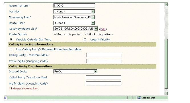
Route Pattern Configuration
Considerations
Calling Name and Number feature
When calling from Cisco 7960 IP phone to Fujitsu digital phone, Calling Name and Number are displayed on both phones after the call is answered as expected.
When calling from Fujitsu digital phone to Cisco 7960 IP phone, IP phone displays Connected Name and Number after the call is answered. Fujitsu phone however displayed "Connected Name" but did not display "Connected Number" when the call is answered. It displays the numbers being dialed instead (i.e. Access code + 7 digit number). It was verified using ISDN protocol analyzer that the CallManager was not sending "Connected Number" information in the connect message back to PBX. Only "Connected Name" was sent in the connect message under the Display IE (0/28) which is an ANSI message format.
Calling Name Display on Fujitsu
Please note the fact that in order for the Fujitsu phone to display Calling Name, the configuration for the Cisco 7960 IP phone's Internal Caller ID field must contain all upper-case characters or numerals. Fujitsu phone will not display lower-case characters.
Appendix A
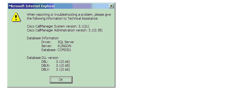
Cisco CallManager Software Release
Fujitsu F9600ES Software release
DIS SOFT (To Display PBX Software Version)01-12-18 TUE 11:31*** SERVICE SOFTWARE LIST ***ALL RIGHTS RESERVED,COPYRIGHT(C)1986 FUJITSU LIMITEDLICENSED MATERIAL PROGRAM PROPERTY OF FUJITSULPE23924 E12V11L22 C00 000314 INSTALLEDNAME TYPE E/VBASCP/D120 360507-D E12V11ATTBS BASIC--D V08IPRCBS 360561-D V06IBRSBS 360562-D V01IPCH0S 360599-D V01IPREBS 360600-D V01IPEH0S 360601-D V01QSIGBS 360974-D V02END 01-12-18 TUE 11:31 (CISCO LAB ES R13)Catalyst 6000 Switch Configuration
Console> (enable) sh versionWS-C6006 Software, Version NmpSW: 5.5(6a)Copyright (c) 1995-2001 by Cisco SystemsNMP S/W compiled on Feb 23 2001, 10:23:18System Bootstrap Version: 5.3(1)Hardware Version: 2.0 Model: WS-C6006 Serial #: TBA04511172Mod Port Model Serial # Versions--- ---- ------------------- ----------- --------------------------------------1 2 WS-X6K-SUP1A-2GE SAD05010NBK Hw : 7.0Fw : 5.3(1)Fw1: 5.4(2)Sw : 5.5(6a)Sw1: 5.5(6a)WS-F6K-PFC SAD05020221 Hw : 1.13 48 WS-X6348-RJ-45 SAD04420N7B Hw : 1.4Fw : 5.4(2)Sw : 5.5(6a)WS-F6K-VPWR Hw : 1.04 24 WS-X6624-FXS SAD050203M8 Hw : 3.0Fw : 5.4(2)Sw : 5.5(6a)HP : A00203010018; DSP : A003H031 (3.3.35)5 8 WS-X6608-T1 SAD04400EM0 Hw : 1.1Fw : 5.4(2)Sw : 5.5(6a)HP1: D00403010017; DSP1: D005E031 (3.3.32)HP2: D00403010025; DSP2: D005H031 (3.3.35)HP3: D00403010025; DSP3: D005H031 (3.3.35)HP4: D00403010025; DSP4: D005H031 (3.3.35)HP5: D00403010025; DSP5: D005H031 (3.3.35)HP6: D00403010025; DSP6: D005H031 (3.3.35)HP7: D00403010025; DSP7: D005H031 (3.3.35)HP8: D00403010025; DSP8: D005H031 (3.3.35)6 8 WS-X6608-E1 SAD04380DW1 Hw : 1.1Fw : 5.4(2)Sw : 5.5(6a)HP1: D00403010025; DSP1: D005H031 (3.3.35)HP2: D00403010025; DSP2: D005H031 (3.3.35)HP3: D00403010025; DSP3: D005H031 (3.3.35)HP4: D00403010025; DSP4: D005H031 (3.3.35)HP5: D00403010025; DSP5: D005H031 (3.3.35)HP6: D00403010025; DSP6: D005H031 (3.3.35)HP7: D00403010025; DSP7: D005H031 (3.3.35)HP8: D00403010025; DSP8: D005H031 (3.3.35)DRAM FLASH NVRAMModule Total Used Free Total Used Free Total Used Free------ ------- ------- ------- ------- ------- ------- ----- ----- -----1 65408K 37844K 27564K 16384K 11546K 4838K 512K 198K 314KUptime is 169 days, 3 hours, 49 minutesConsole> (enable)______________________________________________________________________________Console> (enable) sh moduleMod Slot Ports Module-Type Model Sub Status--- ---- ----- ------------------------- ------------------- --- --------1 1 2 1000BaseX Supervisor WS-X6K-SUP1A-2GE yes ok3 3 48 10/100BaseTX Ethernet WS-X6348-RJ-45 yes ok4 4 24 FXS WS-X6624-FXS no ok5 5 8 T1 WS-X6608-T1 no ok6 6 8 E1 WS-X6608-E1 no okMod Module-Name Serial-Num--- ------------------- -----------1 SAD05010NBK3 SAD04420N7B4 SAD050203M85 SAD04400EM06 SAD04380DW1Mod MAC-Address(es) Hw Fw Sw--- -------------------------------------- ------ ---------- -----------------1 00-04-c0-f8-42-02 to 00-04-c0-f8-42-03 7.0 5.3(1) 5.5(6a)00-04-c0-f8-42-00 to 00-04-c0-f8-42-0100-04-9b-f0-78-00 to 00-04-9b-f0-7b-ff3 00-02-fc-20-5e-50 to 00-02-fc-20-5e-7f 1.4 5.4(2) 5.5(6a)4 00-03-32-ba-2e-35 3.0 5.4(2) 5.5(6a)5 00-01-c9-d9-3a-98 to 00-01-c9-d9-3a-9f 1.1 5.4(2) 5.5(6a)6 00-01-c9-d8-63-3e to 00-01-c9-d8-63-45 1.1 5.4(2) 5.5(6a)Mod Sub-Type Sub-Model Sub-Serial Sub-Hw--- ----------------------- ------------------- ----------- ------1 L3 Switching Engine WS-F6K-PFC SAD05020221 1.13 Inline Power Module WS-F6K-VPWR 1.0Console> (enable)______________________________________________________________________________Console> (enable) sh port 5Port Name Status Vlan Duplex Speed Type----- ------------------ ---------- ---------- ------ ----- ------------5/1 enabled 1 full - unknown5/2 connected 1 full 1.544 T15/3 notconnect 1 full 1.544 T15/4 notconnect 1 full 1.544 T15/5 notconnect 1 full 1.544 T15/6 notconnect 1 full 1.544 T15/7 notconnect 1 full 1.544 T15/8 notconnect 1 full 1.544 T1Port DHCP MAC-Address IP-Address Subnet-Mask-------- ------- ----------------- --------------- ---------------5/1 enable 00-01-c9-d9-3a-98 10.1.1.107 255.255.255.05/2 enable 00-01-c9-d9-3a-99 10.1.1.108 255.255.255.05/3 enable 00-01-c9-d9-3a-9a 10.1.1.109 255.255.255.05/4 enable 00-01-c9-d9-3a-9b 10.1.1.110 255.255.255.05/5 enable 00-01-c9-d9-3a-9c 10.1.1.111 255.255.255.05/6 enable 00-01-c9-d9-3a-9d 10.1.1.112 255.255.255.05/7 enable 00-01-c9-d9-3a-9e 10.1.1.113 255.255.255.05/8 enable 00-01-c9-d9-3a-9f 10.1.1.114 255.255.255.0Port Call-Manager(s) DHCP-Server TFTP-Server Gateway-------- ----------------- --------------- --------------- ---------------5/1 - 10.1.1.2 10.1.1.2 10.1.1.75/2 10.1.1.2 10.1.1.2 10.1.1.2 10.1.1.75/3 10.1.1.2 10.1.1.2 10.1.1.2 10.1.1.75/4 10.1.1.2 10.1.1.2 10.1.1.2 10.1.1.75/5 10.1.1.2 10.1.1.2 10.1.1.2 10.1.1.75/6 10.1.1.2 10.1.1.2 10.1.1.2 10.1.1.75/7 10.1.1.2 10.1.1.2 10.1.1.2 10.1.1.75/8 10.1.1.2 10.1.1.2 10.1.1.2 10.1.1.7Port DNS-Server(s) Domain-------- ----------------- -------------------------------------------------5/1 - -5/2 - -5/3 - -5/4 - -5/5 - -5/6 - -5/7 - -5/8 - -Port CallManagerState DSP-Type-------- ---------------- --------5/1 notregistered C5495/2 registered C5495/3 registered C5495/4 registered C5495/5 registered C5495/6 registered C5495/7 registered C5495/8 registered C549Port NoiseRegen NonLinearProcessing----- ---------- -------------------5/1 - -5/2 enabled enabled5/3 enabled enabled5/4 enabled enabled5/5 enabled enabled5/6 enabled enabled5/7 enabled enabled5/8 enabled enabledConsole> (enable)Test Configuration
Figure 2
Test Topology
As shown in the diagram above, a Fujitsu F9600ES PBX was connected via an ISDN T1 PRI link to a Cisco 6608-T1 Gateway, which in turn, was connected to an Ethernet switch. The interoperability testing involved Layers 1, 2 and 3 on the ISDN PRI link between a Cisco 6608-T1 and the PBX.
Layer 1 (Physical Layer)
The Fujitsu F9600ES PBX was set for Extended Superframe (ESF) and B8ZS linecoding method. Issue DIS TGDC to display Trunk Group Data Control.
Layers 2 & 3 (Q.921 and Q.931)
Layer 2 and 3 packet exchanges were monitored using an Acacia Clarinet protocol analyzer, bridged across the PRI link in high impedance mode.
Layer 2 Q.921 packets were monitored to ensure that each PBX/6608-T1 software configuration properly exchanged SABME/UA packets to initialize the ISDN link, and then RR packets were exchanged every 30 seconds.
Layer 3 Q.931 packets were monitored to ensure that the appropriate call setup/teardown packets were exchanged for each configuration, and that the SETUP packets contained the mandatory Information Elements with the necessary details, as well as optional IEs such as Calling Name and Number.
Telephone calls were made end-to-end in both directions through the Cisco 6608-T1 Gateway, and a check was made to ensure that there was an audio path in both directions for each call.
User/Network Settings
The Cisco 6608-T1 Gateway with ISDN protocol type setting of PRI DMS-100 supports both protocol sides by selecting "Network/User" in the protocol side field when configuring the Gateway via CallManager.
The protocol type and protocol side cannot be changed in the "Change" or "Modify" ISDN trunk screens on the Fujitsu PBX EMML Console. The protocol type and the Master/Slave (or Network/User) settings had to be changed for every test case by deleting and building a new trunk group on the Fujitsu. The Fujitsu "Master" matches up with the Cisco Gateway "User", and Fujitsu 'Slave" matches up with Cisco Gateway "Network". These settings are specified in the fields [MS] (where 0 = slave and 1 = master); and the [PRTCL] field.
Appendix B
Test Results
Testing was performed by Test Engineer(s): Samir Batio, December 20, 2001
Test Setup 1
Test configuration:
•
•
Table 1 Test Setup 1 Switch and Gateway Settings
DMS100 / Master
PRI DMS-100/User
Table 2 Basic Calls: (Enbloc Sending)
Yes
Yes
Yes
No1
Yes
Yes
Yes
Yes
Yes
Yes
1 CallManager is not sending "Connected Number" information in the connect message back to PBX
2 In order for the Fujitsu phone to display "Calling Name", the configuration for the Cisco 7960 IP phone's Internal Caller ID field must contain all upper-case characters or numerals. Fujitsu phone will not display lower-case characters.
Test Setup 2
Test configuration:
•
•
Table 6 Test Setup 2 Switch and Gateway Settings
DMS100 / Slave
PRI DMS-100/Network
The test results are identical as in "Test Setup 1" on page 22. Refer to the tables in "Test Setup 1" on page 22 for details.
![]()
![]()
![]()
![]()
![]()
![]()
![]()
![]()
Posted: Thu Sep 6 13:35:25 PDT 2007
All contents are Copyright © 1992--2007 Cisco Systems, Inc. All rights reserved.
Important Notices and Privacy Statement.