cc/td/doc/product/voice/ata/ataadmn
hometocprevnextglossaryfeedbacksearchhelp
PDF

Table Of Contents

Cisco Analog Telephone Adaptor Overview

Overview of Media Gateway Control Protocol

Hardware Overview

Software Features

MGCP Versions

Voice Codecs Supported

Additional Supported Signaling Protocols

Other Supported Protocols

Cisco ATA MGCP Services

Fax Services

Supplementary Services that the Cisco ATA Provides

Supplementary Services that the Call Agent Provides

Installation and Configuration Overview


Cisco Analog Telephone Adaptor Overview


This section describes the hardware and software features of the Cisco Analog Telephone Adaptor (Cisco ATA) and includes a brief overview of the Media Gateway Control Protocol (MGCP).

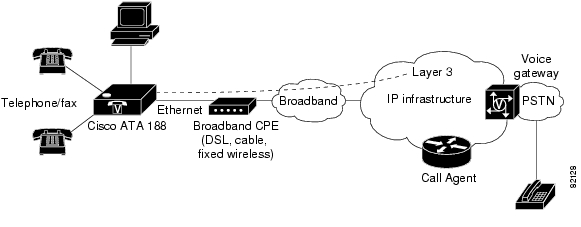
Cisco ATA analog telephone adaptors are handset-to-Ethernet adaptors which allow regular analog telephones to operate on IP-based telephony networks. Cisco ATAs support two voice ports, each with an independent telephone number. The Cisco ATA 188 also has an RJ-45 10/100BASE-T data port.

This section covers the following topics:

Overview of Media Gateway Control Protocol

Hardware Overview

Software Features

Installation and Configuration Overview

Figure 1-1 Cisco ATA Analog Telephone Adaptor

The Cisco ATA, which operates with Cisco voice-packet gateways, makes use of broadband pipes that are deployed by means of a digital subscriber line (DSL), fixed wireless cable modem, and other Ethernet connections.


Note The term Cisco ATA refers to both the Cisco ATA 186 and the Cisco ATA 188, unless otherwise stated.


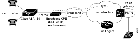
Figure 1-2 The Cisco ATA 186 as an Endpoint in an MGCP Network

Figure 1-3 The Cisco ATA 188 as an Endpoint in an MGCP Network

Overview of Media Gateway Control Protocol

The Media Gateway Control Protocol (MGCP) is the Internet Engineering Task Force (IETF) standard for multimedia conferencing over IP. MGCP is an ASCII-based, application-layer control protocol (defined in RFC2705) that can be used to establish, maintain, and terminate calls between two or more endpoints.

Like other VoIP protocols, MGCP is designed to address the functions of signaling and session management within a packet telephony network.

Signaling allows call information to be carried across network boundaries. Session management provides the ability to control the attributes of an end-to-end call.

One aspect of MGCP that differs from other VoIP protocols is that MGCP endpoints rely on instructions from a Call Agent to control call progression, call tones, and call characteristics.

MGCP provides the following capabilities to the control server:

Determines the location of the target endpoint.

Determines the media capabilities of the target endpoint. Using Session Description Protocol (SDP), MGCP determines the lowest level of common service between the endpoints. Conferences are established using only the media capabilities that can be supported by all endpoints.

Determines the availability of the target endpoint.

Establishes a session between the originating and target endpoint if a call can be completed. MGCP also supports mid-call changes, such as adding another endpoint to the conference or changing a media characteristic or codec.

Each MGCP endpoint supports up to two connections per device. Each connection has a fixed ID—0, 1, 2, or 3. Connection IDs 0 and 2 are assigned to MGCP Endpoint 0, and connection IDs 1 and 3 are assigned to MGCP Endpoint 1.

MGCP is a client-server protocol. The Call Agent handles all aspects of setting up calls to and from endpoints. Call Agents or control servers provide the feature capabilities that a particular endpoint uses. Endpoints connected to different Call Agents likely will have a different set of features.

Each control-server vendor determines its own set of features.

Hardware Overview

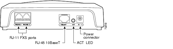
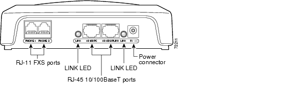
The Cisco ATA 186 and Cisco ATA 188 are compact, easy-to-install devices. Figure 1-4 shows the rear panel of the Cisco ATA 186. Figure 1-5 shows the rear panel of the Cisco ATA 188.

Figure 1-4 Cisco ATA 186—Rear View

Figure 1-5 Cisco ATA 188—Rear View

The unit provides the following connectors and indicators:

5V power connector.

Two RJ-11 FXS (Foreign Exchange Station) ports—The Cisco ATA supports two independent RJ-11 telephone ports that can connect to any standard analog telephone device. Each port supports either voice calls or fax sessions, and both ports can be used simultaneously.


Note The Cisco ATA186-I1 and Cisco ATA188-I1 provide 600-ohm resistive impedance. The Cisco ATA186-I2 and Cisco ATA188-I2 provide 270 ohm + 750 ohm // 150-nF complex impedance. The impedance option is requested when you place your order and should match your specific application. If you are not sure of the applicable configuration, check your country or regional telephone impedance requirements.


Ethernet ports

The Cisco ATA 186 has one RJ-45 10BASE-T uplink Ethernet port to connect the Cisco ATA 186 to a 10/100BASE-T hub or another Ethernet device.

The Cisco ATA 188 has two Ethernet ports: an RJ-45 10/100BASE-T uplink port to connect the Cisco ATA 188 to a 10/100BASE-T hub or another Ethernet device and an RJ-45 10/100BASE-T data port to connect an Ethernet-capable device, such as a computer, to the network.


Note The Cisco ATA 188 performs auto-negotiation for duplexity and speed and is capable of 10/100 Mbps, full-duplex operation. The Cisco ATA 186 is fixed at 10 Mbps, half-duplex operation.


The Cisco ATA 188 RJ-45 LED shows network link and activity. The LED blinks twice when the Cisco ATA is first powered on, then turns off if there is no link or activity. The LED blinks to show network activity and is solid when there is a link.

The Cisco ATA 186 RJ-45 LED is solid when the Cisco ATA is powered on and blinks to show network activity.

Function button—The function button is located on the top panel of the unit (see Figure 1-6).

Figure 1-6 Function Button

The function button lights when you pick up the handset of a telephone attached to the Cisco ATA. The button blinks quickly when the Cisco ATA is upgrading its configuration.


Note If the function button blinks slowly, the Cisco ATA cannot find the DHCP server. Check your Ethernet connections and make sure the DHCP server is available.


Pressing the function button allows you to access to the voice configuration menu. For additional information about the voice configuration menu, see the "Voice Configuration Menu" section on page 3-20.


Caution Never press the function button during an upgrade process. Doing so may interfere with the process.

Software Features

The Cisco ATA supports the following protocols and services:

MGCP Versions

Voice Codecs Supported

Additional Supported Signaling Protocols

Other Supported Protocols

Cisco ATA MGCP Services

Fax Services

Supplementary Services that the Cisco ATA Provides

Supplementary Services that the Call Agent Provides

MGCP Versions

The Cisco ATA supports the following MGCP versions:

MGCP 0.1

MGCP 1.0

NCS 1.0

Voice Codecs Supported

The Cisco ATA supports the following voice codecs (check your other network devices for the codecs they support):

G.711µ-law

G.711A-law

G.723.1

G.729

G.729A

G.729B

G.729.AB

Additional Supported Signaling Protocols

In addition to MGCP, the Cisco ATA supports the following signaling protocols:

Skinny Client Control Protocol (SCCP)

H.323

Session Initiation Protocol (SIP)

If you wish to perform a cross-protocol upgrade from MGCP to another signaling image, see the "Upgrading the Signaling Image from a TFTP Server" section.

Other Supported Protocols

Other protocols that the Cisco ATA supports include the following:

802.1Q VLAN tagging

Cisco Discovery Protocol (CDP)

Domain Name System (DNS)

Dynamic Host Configuration Protocol (DHCP)

Internet Control Message Protocol (ICMP)

Internet Protocol (IP)

Real-Time Transport Protocol (RTP)

Transmission Control Protocol (TCP)

Trivial File Transfer Protocol (TFTP)

User Datagram Protocol (UDP)

Cisco ATA MGCP Services

For a list of required MGCP parameters as well as descriptions of all supported Cisco ATA MGCP services and cross references to the parameters for configuring these services, see "Cisco ATA-Supported MGCP Services."

These services include the following features:

Two MGCP endpoints per Cisco ATA

Two connections per MGCP endpoint

Multiple audio codecs

Events and signals available in MGCP software packages

Automatic MGCP version detection

Caller ID generation

Configurable tone (dial tone, busy tone, confirm tone, reorder tone, call waiting tone)

IP address assignment—DHCP-provided or statically configured

Cisco ATA configuration by means of a TFTP server, web browser, or voice configuration menu.

VLAN configuration

Caller ID format

Ring cadence format

Silence suppression

Low-bit-rate codec selection

RTP media port configuration

Hook-flash detection timing configuration

Cisco Discovery Protocol (CDP)

User interface password

Type of Service (ToS) configuration for audio and signaling ethernet packets

Debugging and diagnostic tools

Fax Services

The Cisco ATA supports two modes of fax services, in which fax signals are transmitted using the G.711 codec:

Fax pass-through mode—Receiver-side Called Station Identification (CED) tone detection with automatic G.711A-law or G.711µ-law switching.

Fax mode—The Cisco ATA is configured as a G.711-only device.

How you set Cisco ATA fax parameters depends on what network gateways are being used. You may need to modify the default fax parameter values (see Chapter 6, "Configuring and Debugging Fax Services").


Note Success of fax transmission depends on network conditions and fax modem response to these conditions. The network must have reasonably low network jitter, network delay, and packet loss rate.


Supplementary Services that the Cisco ATA Provides

Table 1-1 lists the supplementary phone services that the Cisco ATA provides for MGCP. Table 1-1 includes links to the corresponding parameters that allow you to configure these services.

Table 1-1 Supplementary Services that Require Configuration on the Cisco ATA

Service
Parameter

Caller ID

CallerIdMethod, page 5-21

Call Waiting

SigTimer, page 5-26

Call-Waiting-Caller ID

CallerIdMethod, page 5-21, SigTimer, page 5-26

Three-way Conference

ConnectMode, page 5-24—Bit 23


Supplementary Services that the Call Agent Provides

The Cisco ATA supports the following services that are provided by the Call Agent:


Note For end-user information on how these services work, consult the documentation from the MGCP Call Agent service provider.


Anonymous Call Rejection

Call forward—on busy

Call forward—on no answer

Call forward—unconditional

Call hold

Caller ID

Calling Line Identification Presentation

Calling Line Identification Restriction

Call return

Call transfer—Blind

Call transfer—Consultation

Call waiting

Call waiting Caller ID

Distinctive ringing

Message-waiting-indication (stuttering dial tone)

Speed dial

Three-way conference

Voice mail

Installation and Configuration Overview

Table 1-2 provides the basic steps required to install and configure the Cisco ATA to make it operational in a typical MGCP environment.

Table 1-2 Overview of the Steps Required to Install and Configure the Cisco ATA and Make it Operational 

Action
Reference

1. Plan the network and Cisco ATA configuration.


2. Install the Ethernet connection.


3. Install and configure the other network devices.


4. Install the Cisco ATA but do not power up the Cisco ATA yet.

What the Cisco ATA Package Includes

5. Download the desired Cisco ATA release software zip file from the Cisco web site, then configure the Cisco ATA.

Chapter 3, "Configuring the Cisco ATA for MGCP"

6. Power up the Cisco ATA.


7. Periodically, you can upgrade the Cisco ATA to a new signaling image by using the TFTP server-upgrade method or the manual-upgrade method.

"Upgrading the Cisco ATA Signaling Image"


hometocprevnextglossaryfeedbacksearchhelp

Posted: Thu Feb 9 14:15:21 PST 2006
All contents are Copyright © 1992--2006 Cisco Systems, Inc. All rights reserved.
Important Notices and Privacy Statement.