|
|

Table Of Contents
Configuration Text File Template
User Interface (UI) Security Parameter
Parameters for Configuration Method and Encryption
Network Configuration Parameters
Audio Configuration Parameters
Tone Parameter Syntax—Basic Format
Tone Parameter Syntax—Extended Formats
Specific Tone Parameter Information
CFGID—Version Parameter for Cisco ATA Configuration File
Parameters and Defaults
This section provides information on the parameters and defaults that you can use to create your own Cisco ATA configuration file. This section also includes the voice configuration menu code for each parameter that has such a code.
Parameters are divided into categories based on their functionality. The following categories of parameters are covered in this section:
•
User Interface (UI) Security Parameter
•
•
•
•
•
•
The following list contains general configuration information:
•
•
–
–
–
–
Note
Note
–
–
–
–
Note
Note
Configuration Text File Template
This is a listing of the mgcp_example.txt text file, without its annotations, that comes bundled with the Cisco ATA software.
You can make a copy of this file and use it as a template for creating your own default configuration file or Cisco ATA-specific configuration file. For instructions on how to create these configuration files, see the "Creating Unique and Common Cisco ATA Configuration Files" section on page 3-9.
The mgcp_example.txt file contains all the Cisco ATA default values. A configuration file must begin with #txt so that the formatting tool, cfgfmt.exe, treats the file as a text file. The sections that follow this listing describe all the parameters in this file.
#txtUIPassword:0UseTftp:1TftpURL:0CfgInterval:3600EncryptKey:0upgradecode:0,0x301,0x0400,0x0200,0.0.0.0,69,0,noneupgradelang:0,0x301,0x0400,0x0200,0.0.0.0,69,0,noneDhcp:1StaticIp:0StaticRoute:0StaticNetMask:0DNS1IP:0.0.0.0DNS2IP:0.0.0.0VLANSetting:0x0000002bCA0orCM0:0CA1orCM1:0CA0UID:0CA1UID:0EPID0orSID0:.EPID1orSID1:.PrfCodec:1LBRCodec:3MGCPPort:2427MediaPort:16384RetxIntvl:500RetxLim:10MGCPVer:MGCP1.0Domain:.CodecName:PCMU,PCMA,G723,G729AudioMode:0x00350035NumTxFrames:2CallerIdMethod:0x00019e60Polarity:0FXSInputLevel:-1FXSOutputLevel:-4ConnectMode:0x00000400SigTimer:0x00000064OpFlags:0x00000002TOS:0x000068B8DialTone:2,31538,30831,1380,1740,1,0,0,1000BusyTone:2,30467,28959,1191,1513,0,4000,4000,0ReorderTone:2,30467,28959,1191,1513,0,2000,2000,0RingBackTone:2,30831,30467,1943,2111,0,16000,32000,0CallWaitTone:1,30831,0,5493,0,0,2400,2400,4800AlertTone:1,30467,0,5970,0,0,480,480,1920RingCadence:2,4,25NPrintf:0TraceFlags:0x00000000SyslogIP:0.0.0.0.514SyslogCtrl:0x00000000User Interface (UI) Security Parameter
This parameter type contains one parameter—UIPassword.
UIPassword
Description
This parameter controls access to web page or voice configuration menu interface. To set a password, enter a value other than 0.
To clear a password, change the value to 0.
You cannot recover a forgotten password unless you reset the entire configuration of the Cisco ATA (see the "Resetting the Cisco ATA to Factory Default Values" section on page 3-23).
Note
Value Type
Alphanumeric string
Range
Maximum nine characters
Default
0
Voice Configuration Menu Access Code
7387277
Parameters for Configuration Method and Encryption
This section describes parameters for instructing the Cisco ATA how to locate its TFTP server and how to encrypt its configuration file. These parameters are:
•
•
UseTFTP
Settings
1—Use the TFTP server for Cisco ATA configuration.
0—Do not use the TFTP server for Cisco ATA configuration.
Value Type
Boolean
Range
0 or 1
Default
1
Voice Configuration Menu Access Code
305
Related Parameters
•
•
TftpURL
Description
Use this parameter to specify the IP address or URL of the TFTP server. This string is needed if the DHCP server does not provide the TFTP server IP address. When the TftpURL parameter is set to a non-zero value, this parameter has priority over the TFTP server IP address supplied by the DHCP server.
Optionally, you can include the path prefix on the TFTP server from which the Cisco ATA will download its configuration file.
For example, if the TFTP server IP address is 192.168.2.170 or www.cisco.com, and the path prefix for the configuration file on the TFTP server is in /ata186, you can specify the URL as 192.168.2.170/ata186 or www.cisco.com/ata186.
Note
Value Type
Alphanumeric string
Range
Maximum 31 characters
Default
0
Voice Configuration Menu Access Code
905
Related Parameters
•
CfgInterval
Description
Use this parameter to specify the number of seconds between each configuration update. The Cisco ATA will also upgrade its signaling image it it detects that the TFTP server contains an upgraded image.
When using TFTP for configuration, the Cisco ATA contacts TFTP each time the interval expires to get its configuration file.
You can set CfgInterval to a random value to achieve random contact intervals from the Cisco ATA to the TFTP server.
Value Type
Decimal
Range
60 to 4294967295
Default
3600
Voice Configuration Menu Access Code
80002
EncryptKey
Description
This parameter specifies the encryption key that is used to encrypt the Cisco ATA configuration file on the TFTP server.
The cfgfmt tool, which is used to create a Cisco ATA binary configuration file (see the ), automatically encrypts the binary file when the EncryptKey parameter has a value other than 0. The cfgfmt tool uses the rc4 encryption algorithm.
If this parameter value is set to 0, the Cisco ATA configuration file on the TFTP server is not encrypted.
Note
For examples on how to upgrade from the EncryptKey parameter to the stronger encryption method that uses the EncryptKeyEx parameter, see the "Examples of Upgrading to Stronger Encryption Key" section on page 3-15.
Value Type
Hexadecimal string
Range
Maximum number of characters: 8
Default
0
Voice Configuration Menu Access Code
320
Related Parameters
•
•
EncryptKeyEx
Description
This parameter specifies an encryption key that is stronger than the key specified with the EncryptKey parameter. This stronger key is used to encrypt the Cisco ATA configuration file on the TFTP server.
Note
When the EncryptKeyEx parameter is set to a non-zero value, the Cisco ATA uses this value as the encryption key and ignores any value that has been set for the EncryptKey parameter. The cfgfmt tool, which is used to create a Cisco ATA binary configuration file (see the "Using Encryption With the cfgfmt Tool" section on page 3-12), automatically encrypts the binary file using the stronger rc4 encryption algorithm.
When EncryptKeyEx is used for encryption, the Cisco ATA searches for the configuration file with the format ata<macaddress>.x. on the TFTP server.
If the value of the EncryptKeyEx parameter is 0, then the Cisco ATA uses the value of the EncryptKey parameter for encryption.
Note
For examples on how to upgrade from the EncryptKey parameter to the stronger encryption method that uses the EncryptKeyEx parameter, see the "Examples of Upgrading to Stronger Encryption Key" section on page 3-15.
Value Type
Hexadecimal string of the form:
Rc4PasswdInHex/macinHex_12
•
•
Range
Maximum number of characters: 64
Default
0
Voice Configuration Menu Access Code
Not applicable for this parameter.
Related Parameters
•
•
Network Configuration Parameters
This section includes the parameters for enabling or disabling the use of a DHCP server to obtain IP address information, and parameters that you need to statically configure if you disable DHCP:
•
•
•
•
DHCP
Description
This parameter can be used to automatically set the IP address of the Cisco ATA, the network route IP address, the subnet mask, DNS, NTP, TFTP, and other parameters.
•
•
Value Type
Boolean
Range
0 or 1
Default
1
Voice Configuration Menu Access Code
20
Related Parameters
•
•
StaticIp
Description
Configure the Cisco ATA IP address using this parameter if the DHCP parameter is set to 0.
Value Type
IP address
Default
0.0.0.0
Voice Configuration Menu Access Code
1
Related Parameters
•
StaticRoute
Description
Configure the Cisco ATA statically assigned route in this parameter if the DHCP parameter is set to 0.
Value Type
IP address
Default
0.0.0.0
Voice Configuration Menu Access Code
2
Related Parameters
•
•
StaticNetMask
Description
Configure the statically assigned subnet mask using this parameter if the DHCP parameter is set to 0.
Value Type
IP address
Default
255.255.255.0
Voice Configuration Menu Access Code
10
Related Parameters
•
•
DNS1IP
Description
This parameter is for setting the primary domain name server (DNS) IP address, if the DHCP server does not provide one. If DHCP provides DNS1IP (and if it is non-zero), this parameter overwrites the DHCP-supplied value. You cannot specify a port parameter. The Cisco ATA uses the default DNS port only.
Value Type
IP address
Default
0.0.0.0
Voice Configuration Menu Access Code
916
DNS2IP
Description
This parameter is for setting the secondary domain name server (DNS) IP address, if the DHCP server does not provide one. If DHCP provides DNS2IP (if it is non-zero), this parameter overwrites the DHCP-supplied value. You cannot specify a port parameter. The Cisco ATA uses the default DNS port only.
Value Type
IP address
Default
0.0.0.0
Voice Configuration Menu Access Code
917
VLAN Setting
Description
This parameter is for software versions 2.14.ms, 2.15.ms, and later.
Bitmap definitions are as follows for the VLAN Setting parameter:
•
•
•
•
•
Value Type
Bitmap
Default
0x0000002b
Voice Configuration Menu Access Code
324
Related parameter
MGCP Configuration Parameters
This section describes the following parameters, which include Call Agent parameters:
•
•
•
•
•
•
•
•
•
•
CA0orCM0
Description
Specify the primary Call Agent in this parameter. This parameter must be an IP address or URL and may include a port parameter. The default port number is 2727.
If you specify a port, you must separate the port number from the host IP address with a colon (:).
Examples
Examples of CA0orCM0 values follow:
•
•
Value Type
Alphanumeric string
Range
Maximum 31 characters
Default
0
Voice Configuration Menu Access Code
5
CA1orCM1
Description
Specify the alternate Call Agent in this parameter. This parameter must be an IP address or URL and may include a port parameter. The default port number is 2727.
If you specify a port, you must separate the port number from the host IP address with a colon (:).
Note
Examples
Examples of CA1orCM1 values follow:
•
•
Value Type
Alphanumeric string
Range
Maximum 31 characters
Default
0
Voice Configuration Menu Access Code
6
CA0UID
Description
Specify the ID of the primary Call Agent in this parameter.
Value Type
Alphanumeric string
Range
Maximum 31 characters
CA1UID
Description
Specify the ID of the secondary Call Agent in this parameter.
Value Type
Alphanumeric string
Range
Maximum 31 characters
EPID0orSID0 and EPID1orSID1
Description
EPIDx (for MGCP only) specifies the alphanumeric Endpoint Identifier assigned to line x of the Cisco ATA, where x=0 or 1. The complete Endpoint Identifier sent to the Call Agent has the format <EPIDx>@<ip_addr>. (SIDx does not apply to MGCP.) To enable the usage of square brackets around the IP address of the endpoint, enable Bit 20 of the ConnectMode parameter. (See the "ConnectMode" section.)
Note
Value Types
Alphanumeric string for each parameter
Default
.—The dot is the default and means that the value of aaln/1 is used as the MGCP endpoint ID for EPID1 and aaln/2 is used as the MGCP endpoint name for EPID2.
Range
Maximum 51 characters for each parameter
Voice Configuration Menu Access Codes
46 and 47 for EPID0orSID0 and EPID1orSID1, respectively
PrfCodec
Description
This parameter specifies the default preferred codec. The preferred codec is used only when the Call Agent does not provide a list of preferred codecs in the Local Connection Options 'a' parameter and when the remote party does not include a codec preference in its SDP.
The following values are valid:
0=G.723.1 (only if LBRCodec=0)
1=G.711A-law
2=G.711u-law
3=G.729a (only if LBRCodec=3)
Value Type
Integer
Range
0 to 3
Default
1
Voice Configuration Menu Access Code
36
LBRCodec
Description
This parameter is used for selecting the low-bit-rate codec. The following values are valid:
•
•
If LBRCodec=0, then both Cisco ATA FXS ports can operate with the following codecs:
•
•
•
•
If LBRCodec=3, check the setting of bit 21 in the ConnectMode parameter (see the "ConnectMode" section) to determine if G.729 is enabled for the Phone 1 or Phone 2 FXS port.
If LBRCodec=3, then the Phone 1 FXS port can operate with the following codecs:
•
•
•
•
•
If LBRCodec=3, then the Phone 2 FXS port can operate with the following codecs:
•
•
•
•
Value Type
Integer
Range
0 or 3
Default
3
Voice Configuration Menu Access Code
300
MGCPPort
Description
This parameter specifies the listening port for Media Gateway Control (MGCP) messages on the Cisco ATA. The Cisco ATA also sends MGCP messages from this port. Using the same port for sending and receiving messages may facilitate passage through Network Address Translation (NAT).
Value Type
Integer
Range
1 to 65535
Default
2427
Voice Configuration Menu Access Code
201
MediaPort
Description
Use this parameter to specify the base port where the Cisco ATA transmits and receives RTP media. This parameter must be an even number. Each connection uses the next available even-numbered port for RTP.
Value Type
Integer
Range
1 to 65535
Default
16384
Voice Configuration Menu Access Code
202
RetxIntvl
Description
This parameter specifies the first retransmission interval of MGCP commands (in milliseconds). Subsequent retransmission periods double the previous interval (exponential backoff).
Value Type
Integer
Range
1 to 20000
Default
500
Voice Configuration Menu Access Code
203
RetxLim
Description
This parameter specifies the maximum number of times the Cisco ATA retransmits commands. When this value is exceeded, the Cisco ATA terminates its connection to the Call Agent and restarts.
Value Type
Integer
Range
1 to 4294967295
Default
10
Voice Configuration Menu Access Code
205
MGCPVer
Description
Enter the MGCP version string that the Cisco ATA should use when it powers on. The following values are valid:
•
•
•
Note
Value Type
Alphanumeric
Default
MGCP1.0
Voice Configuration Menu Access Code
206
Domain
Description
The Cisco ATA uses this parameter to determine how the domain-name portion of the endpoint identifier is constructed. The following values are valid:
•
•
•
•
•
Value Type
Alphanumeric string
Range
Maximum 31 characters
Default
.
Voice Configuration Menu Access Code
931
Audio Configuration Parameters
:This section contains information about the following parameters:
CodecName
Description
This parameter specifies the names of the encoder/decoders to use in the LocalConnectionOption parameter. You must list the names in the following order:
•
•
•
•
Note
Value Type
Alphanumeric string
Range
The following list shows the maximum number of characters allowed for the respective codec names:
•
•
•
•
If a codec name is longer than the maximum, the default standard-based name is used.
Default Names
•
•
•
•
Voice Configuration Menu Access Code
Not applicable
AudioMode
Description
This parameter represents the audio operating mode. The lower 16 bits are for the Phone 1 port, and the upper 16 bits are for the Phone 2 port. Table 5-1 provides definitions for each bit.
Value Type
Bitmap
Default
0x00350035
Voice Configuration Menu Access Code
312
NumTxFrames
Description
Use this parameter to select the default RTP packet size in number of frames per packet. The Cisco ATA default frame sizes are as follows:
•
•
For example, to receive 20 ms of G.729 packets, set the parameter to 2.
Value Type
Integer
Range
1-6
Default
2
Voice Configuration Menu Access Code
35
Operational Parameters
This section includes parameters that are used for configuring the connection mode of the Cisco ATA as well as for disabling or enabling various operational features:
•
•
•
CallerIdMethod
Description
This 32-bit parameter specifies the signal format to use for both FXS lines for generating Caller ID format. The following values are allowed:
•
If method=0, set the following bits:
•
•
•
•
Note
If method=1, set the following bits:
•
•
•
•
•
•
•
•
•
•
•
•
•
•
If method=2, set the following bits:
•
•
•
•
•
•
Examples
The following examples are recommended values for the CallerID Method parameter:
•
•
•
Value Type
Bitmap
Default
0x00019e60
Voice Configuration Menu Access Code
316
FXSInputLevel
Description
Use this parameter to specify the input level control (analog-to-digital path) of the Cisco ATA FXS ports.
Value Type
Integer
Range
-9 to 2 dB
Default
-1
Voice Configuration Menu Access Code
370
Related Parameter
FXSOutputLevel
Description
Use this parameter to specify the output level control (digital-to-analog path) of the Cisco ATA FXS ports.
Value Type
Integer
Range
-9 to 2 dB
Default
-4
Voice Configuration Menu Access Code
371
Related Parameter
ConnectMode
Description
This parameter is a 32-bit bitmap to control the connection mode of the selected call signaling protocol. Table 5-2 provides bit definitions for this parameter.
Value Type
Bitmap
Default
0x90000400
Voice Configuration Menu Access Code
311
Table 5-2 ConnectMode Parameter Bit Definitions
0-1
Reserved.
2
0—Use the dynamic payload type 126/127 as the RTP payload type (fax pass-through mode) for G.711 µ-law/G.711 A-law.
1—Use the standard payload type 0/8 as the RTP payload type (fax pass-through mode) for G.711 µ-law/G.711 A-law.
Default: 0
3-6
Reserved.
7
0/1—Disable/enable fax pass-through redundancy.
Default: 0
8-12
Specifiy the fax pass-through NSE payload type with these bits. The value is the offset to the NSE payload base number of 96. The valid range is 0-23; the default is 4.
For example, if the offset is 4, the NSE payload type is 100.
13
0—Use G.711µ-law for fax pass-through codec.
1—Use G.711A-law for fax pass-through codec.
Default: 0
14-15
0—Use fax pass-through.
1—Use codec negotiation in sending fax.
2,3—Reserved.
Default: 0
16
0—Use non-NCS-compliant Session Description Protocol (SDP).
1—Use NCS-compliant SDP.
Default: 0
17
0/1—Disable/enable automatic MGCP-version detection.
Default: 0
18
0/1—Enable/disable persistent on-hook and off-hook events.
Default: 0
19
0/1—Enable/disable persistent hook-flash events.
Default: 0
20
0/1—Disable/enable using a pair of brackets to enclose the IP address of an endpoint identifier. For more information, see the "Endpoints and Connections" section.
Default: 0
21
0—Enables G.729 codec on the Phone 1 port.
1—Enables G.729 codec on the Phone 2 port.
Default: 0
22
0—Use loop mode for quarantine handling.
1—Use step mode for quarantine handling.
Default: 0
23
0/1—Disable/enable conference connection mode.
Default: 0
24
0/1—Enable/disable support for RSIP*@ipaddress syntax. For more information, see the "Cisco ATA Registration Process with MGCP" section.
Default: 0
25-31
Reserved.
SigTimer
Description
This parameter controls various timeouts. Table 5-3 contains bit definitions of this parameter.
Value Type
Bitmap
Default
0x00000064
Voice Configuration Menu Access Code
318
OpFlags
Description
Enables/disables various operational features.
See Table 5-4 for bit definitions of this parameter.
Value Type
Bitmap
Default
0x2
Voice Configuration Menu Access Code
323
Table 5-4 OpFlags Parameter Operational Features to Turn On or Off
0
If Bit 0 = 0, the TFTP configuration filename supplied by the DHCP server overwrites the default filename for each Cisco ATA.
If Bit 0 = 1, the default Cisco ATA filename is always used.
Default: 0
1
If Bit 1 = 0, the Cisco ATA probes the static network router during the power-up process.
If Bit 1 = 1, static network router probing is disabled.
Default: 1
2
Reserved.
3
If Bit 3=1, the Cisco ATA does not request DHCP option 150 in the DHCP discovery message; some DHCP server do not respond if option 150 is requested.
Default: 0
4
If Bit 4 = 1, the Cisco ATA uses the VLAN ID specified in the VLANSetting parameter for VLAN IP encapsulation (see the "VLAN Setting" section).
Default: 0
5
If Bit 5=1, the Cisco ATA does not use VLAN IP encapsulation.
Default: 0
6
If Bit 6=1, the Cisco ATA does not perform CDP discovery.
Default: 0
7
If Bit 7=1, the Cisco ATA does not allow web-based configuration.
Default: 0
8
If Bit 8=1, the Cisco ATA does not allow HTTP refresh access with the http://ip/refresh command.
Default: 0
9
If Bit 9=1, the Cisco ATA does not allow HTTP reset access with the http://ip/reset command.
Default: 0
10
Reserved.
11
If Bit 11=0, the Cisco ATA requests the device hostname from the DHCP server.
If Bit 11=1, the Cisco ATA uses the device hostname that is specified in DHCP option 12.
Default: 0
12
Reserved.
13
If Bit 13=0 (default), use statically configured DNS IP addresses, if available, for name resolution. If statically configured DNS servers are not available, use DHCP-provided DNS IP addresses for name resolution.
If Bit 13=1, use both statically configured DNS IP addresses and as many as two DHCP-provided DNS IP addresses. Therefore, the Cisco ATA can query as many as four DNS IP addresses in one DNS query.
For more information about statically configured DNS IP addresses, see the "DNS1IP" section section and the "DNS2IP" section section.
Default: 0
14-31
Reserved.
TOS
Description
This parameter allows you to configure Type of Service (ToS) bits by specifying the precedence and delay of audio and signaling IP packets, as follows:
•
–
–
•
–
–
•
Value Type
Bitmap
Default
0x000068B8
Voice Configuration Menu Access Code
255
Note
Tone Configuration Parameters
The Cisco ATA supports the following tone parameters:
•
•
•
•
•
•
The Cisco ATA supports two types of tone-parameter syntax—basic format and extended format. Basic format is used in most countries; use the extended format only if the country in which the Cisco ATA is used requires this format.
This section covers all the call-progress tones that the Cisco ATA supports, and contains the following topics:
•
•
•
This section also covers the following parameter, which is for configuring phone-ringing characteristics:
Note
Tone Parameter Syntax—Basic Format
Each tone is specified by nine integers, as follows:
parametername: NumOfFreqs,Tfreq1,Tfreq2,Tamp1,Tamp2,Steady,OnTime,OffTime, TotalToneTime•
•
•
32767 * cos (2*pi*F/8000)
where F is the desired frequency in Hz. Set this value to 0 if the frequency does not exist.
The range of each value is -32768 to 32767.
For negative values, use the 16-bit 2's complement value. For example, enter -1 as 65535 or as 0xffff.
•
32767 * A * sin(2*pi*F/8000)
A (amplitude factor) = 0.5 * 10^((k+10-(n-1)*3)/20)
where F is the desired frequency in Hz, k is the desired volume in dBm, and n is the number of frequencies. The ^ symbol means to the order of.
•
•
Specify each value as a number of samples with a sampling rate of 8 kHz. The range of each value is 0 to 0xffff. For example, for a length of 0.3 seconds, set the value to 2400.
•
Specify each value as a number of samples with a sampling rate of 8 kHz. The range of each value is 0 to 0xffff. For example, for a length of 0.3 seconds, set the value to 2400.
•
For the remaining tones, the configurable value is the number of samples with a sampling rate of 8 kHz.
Note
Tone Parameter Syntax—Extended Formats
Two types of extended format exist for the Cisco ATA tone parameters:
•
–
–
–
–
–
•
Extended Format A
Each tone is specified by 11 integers, as follows:
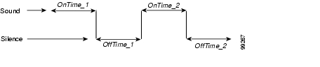
parametername:NumOfFreqs,Tfreq1,Tamp1,Tfreq2,Tamp2,NumOfOnOffPairs,OnTime1,
OffTime1,OnTime2,OffTime2,TotalToneTime
•
•
•
32767 * cos (2*pi*F/8000)
where F is the desired frequency in Hz. Set this value to 0 if the frequency does not exist.
The range of each value is -32768 to 32767.
For negative values, use the 16-bit 2's complement value. For example, enter -1 as 65535 or as 0xffff.
•
32767 * A * sin(2*pi*F/8000)
A (amplitude factor) = 0.5 * 10^((k+10-(n-1)*3)/20)
where F is the desired frequency in Hz, k is the desired volume in dBm, and n is the number of frequencies. The ^ symbol means to the order of.
•
Valid values are 0, 1 and 2. Use 0 if the tone is steady.
•
Specify each value as a number of samples with a sampling rate of 8 kHz. The range of each value is 0 to 0xffff. For example, for a length of 0.3 seconds, set the value to 2400.
•
Specify each value as a number of samples with a sampling rate of 8 kHz. The range of each value is 0 to 0xffff. For example, for a length of 0.3 seconds, set the value to 2400.
Figure 5-1 Cadence With Two On-Off Pairs
•
For the remaining tones, the configurable value is the number of samples with a sampling rate of 8 kHz.
Note
Extended Format B
The ReorderTone parameter specifies the tone that the Cisco ATA plays when the called number is not available or the external circuit is busy. This tones can consist of:
•
For example, a 400 Hz frequency plays four times for 0.75 second followed by 0.1 second of silence after each play and then plays one time for 0.75 second followed by 0.4 second of silence. This pattern can be set to repeat until another call event stops the pattern.
•
For example, the frequencies 900 Hz, 1400 Hz, and 1800 Hz play sequentially for 0.33 seconds each with no silence after the first and second frequencies but one second of silence after the third frequency.
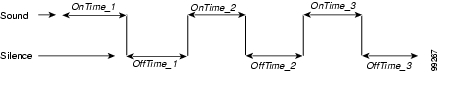
The syntax of the ReorderTone parameter is specified by 17 integers, as follows:
ReorderTone:Sequential,NumOfFreqs,TFreq1,Tamp1,TFreq2,
Tamp2,TFreq3,Tamp3,NumOfOnOffPairs,OnTime1,OffTime1,
OnTime2,OffTime2,OnTime3,OffTime3,NumOfRepeats,TotalToneTime
where:
•
•
•
32767 * cos (2 * pi * F/8000)
where F is the desired frequency in Hz. Set this value to 0 if the frequency does not exist.
The range of each value is -32768 to 32767.
For negative values, use the 16-bit 2's complement value. For example, enter -1 as 65535 or as 0xffff.
•
32767 * A * sin(2*pi*F/8000)
A (amplitude factor) = 0.5 * 10^((k+10-(n-1)*3)/20)
where F is the desired frequency in Hz, k is the desired volume in dBm, and n is the number of frequencies (If Sequential is set to 101, n is equal to 1). The ^ symbol means to the order of.
•
If this value is 0, the OnTime1, OnTime2, OnTime 3, OffTime1, OffTime2, and OffTime3 values must also be 0.
•
Specify each value as a number of samples with the sampling rate of 8 kHz. The range of each value is 0 to 0xffff.
For example, for a length of 0.3 seconds, set a value to 2400.
•
Specify each value as a number of samples with the sampling rate of 8 kHz. The range of each value is 0 to 0xffff.
For example, for a length of 0.3 seconds, set a value to 2400. (See Figure 5-2 for a graphical representation.)
Figure 5-2 Cadence with Three On-Off Pairs
•
For example, if NumOfRepeats is 2, the first on-off pair will play three times (it will play once and then repeat two times), then the second on-off pair will play.
•
This value is in 10 ms units (100 ms = 1 second).
Two examples of Extended Format B, both using the Reorder tone, follow.
ReorderTone Parameter Example1
Assume that you want a reorder tone in which:
•
•
•
•
•
•
For this reorder tone, make the following setting. See Table 5-5 for a detailed explanation.
ReorderTone:101,3,24917,3405,14876,4671,5126,5178,3,2640,0,2640,0,
2640,8000,0,0
ReorderTone Parameter Example 2
Assume that you want a reorder tone in which:
•
•
•
•
•
For this reorder tone, make the following setting. See Table 5-6 for a detailed explanation.
ReorderTone:100,1,31164,1620,0,0,0,0,2,800,7200,2400,5600, 0,0,5,0
Recommended Values
The following settings are recommended for the US:
•
•
•
•
•
•
Note
Specific Tone Parameter Information
Brief descriptions, and lists of default values and the voice configuration menu code for each Cisco ATA tone parameter, appear in the following sections:
•
•
DialTone
Description
The Cisco ATA plays the dial tone when it is ready to accept the first digit of a remote address to make an outgoing call.
Default values (using the Basic format)
•
•
•
•
•
•
•
•
•
Voice Configuration Menu Access Code
920
BusyTone
Description
The Cisco ATA plays the busy tone when the callee is busy.
Default values (using the Basic format)
•
•
•
•
•
•
•
•
•
Voice Configuration Menu Access Code
921
ReorderTone
Description
The Cisco ATA plays the reorder tone (also known as congestion tone) if the outgoing call failed for reasons other than busy. This is a fast-busy tone.
Default values (using the Basic format)
•
•
•
•
•
•
•
•
•
Voice Configuration Menu Access Code
922
RingbackTone
Description
The Cisco ATA plays the ring-back tone when the callee is being alerted by the called device.
Default values (using the Basic format)
•
•
•
•
•
•
•
•
•
Voice Configuration Menu Access Code
923
CallWaitTone
Description
The Cisco ATA plays the call-waiting tone when an incoming call arrives while the user is connected to another party.
Default values (using the Basic format)
•
•
•
•
•
•
•
•
•
Voice Configuration Menu Access Code
924
AlertTone
Description
The Cisco ATA plays the alert tone as a confirmation tone that a special event, such as call forwarding, is in effect.
Default values (using the Basic format)
•
•
•
•
•
•
•
•
•
Voice Configuration Menu Access Code
925
RingCadence
Description
Use this parameter to specify the internal and external ringer cadence pattern, expressed as a triplet of integers "a,b, and c".
•
•
•
Value Type
List of three integer values, separated by commas
Range
1-65535
Default
2, 4, 25
Recommended Values:
•
•
Voice Configuration Menu Access Code
929
Diagnostic Parameters
This section describes the following parameters, which are used for diagnostic purposes
•
•
NPrintf
Description
Use this parameter to specify the IP address and port of a host to which all Cisco ATA debug messages are sent. The program prserv.exe, which comes bundled with the Cisco ATA software, is needed to capture the debug information.
Syntax
<HOST_IP>,<HOST_PORT>
Example
If the program prserv.exe is running on a host with IP address 192.168.2.170 and listening port 9001, set NPrintf to 192.168.2.170.9001. This causes the Cisco ATA to send all debug traces to that IP address.
Value Type
Extended IP address
Default
0
Voice Configuration Menu Access Code
81
TraceFlags
Description
This parameter is reserved in MGCP. The Cisco ATA will output all MGCP messages regardless of this parameter value.
Value Type
Bitmap
Default
0x00000000
Voice Configuration Menu Access Code
313
SyslogIP
Description
Use this parameter for diagnostic purposes; specify the IP address and port number to which the Cisco ATA should send its syslog output information.
The program prserv.exe, which is included in all Cisco ATA software upgrade packages, can be used to capture syslog information if you do not have a syslog server.
Syntax
<HOST_IPaddress>.<HOST_PORT>
Example
If you want to send syslog information to the host at IP address 192.168.2.170 and port number 514, do the following:
•
•
prserv 514Value Type
Extended IP address
Default
0.0.0.0.514
Voice Configuration Menu Access Code
7975640
Related Parameter
SyslogCtrl
Description
Use this parameter to turn on specific syslog traces. All traces are sent to the syslog server specified in the SyslogIP parameter.
See Table 5-7 for bit values and the corresponding types of messages to turn on for tracing.
Value Type
Bitmap
Default
0x00000000
Voice Configuration Menu Access Code
7975641
Related Parameter
CFGID—Version Parameter for Cisco ATA Configuration File
Description
CFGID is a 32-bit unsigned-value parameter whose purpose is to allow the local administrator to track the version of the Cisco ATA configuration file. This parameter-value assignment is entirely the responsibility of the local administrator, and has no significance to the operation of the Cisco ATA.
Value Type
Bitmap
Default
0x00000000
![]()
![]()
![]()
![]()
![]()
![]()
![]()
![]()
Posted: Thu Feb 9 13:18:01 PST 2006
All contents are Copyright © 1992--2006 Cisco Systems, Inc. All rights reserved.
Important Notices and Privacy Statement.