|
|

Data between the system and the host computer is passed over one or more communications links. Regardless of the protocol chosen by the application designer, the format of the message data transferred over the links remains the same. This section provides an overview of the system message structure.
A system message can consist of as few as 6 and as many as 512 bytes of information, depending on the command or report type. In spite of this variation in length, the message structure is consistent, as shown in Figure 3-1.
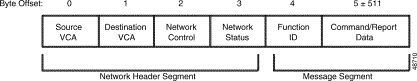
Each message consists of a Network Header Segment and a Message Segment. The sections that follow explain the bytes contained in the Network Header Segment. The Message Segment (Function ID and Command/Report Data) is discussed in "System Commands," and "System Reports."
The Source Virtual Communications Address (VCA) is the hex representation of the logical identifier assigned to the equipment that originated the message. This address is independent of any station identifiers required by the protocol.
Messages sourced by the system use the global VCA $DF unless that value has been changed by the receipt of a Configure VCA/Set System Clock ($C0 00) command. The new VCA remains set through system reset and power-down cycles.
Messages that originate from the host computer should have a source VCA different from any that has been assigned to the system.
The destination virtual communications address (VCA) is the hex representation of the logical identifier assigned to the equipment to which the message is sent. This address is independent of any station identifiers required by the protocol.
A received message is not processed unless the Destination VCA matches the VCA assigned to that particular system. Every system responds to the global VCA $DF, regardless of any address assignments.
The system assigns a Destination VCA to messages to the host. This address, which is determined by the report type, is summarized in Table 3-1. Host network layer processing can use the destination VCA to route reports to specific tasks.
In systems that use more than one link between the system and the host, the system network layer chooses the links over which the message is broadcast based on report type and call status. The three options—requesting link, controlling link, and all links—are described below. The applicable reports are shown in Table 3-1.
| Report | VCA | Link | |
|---|---|---|---|
Resource Allocation ($80) | Variable1 | R |
|
Hardware Allocation ($81) | Variable1 | R |
|
MF Digit Report ($D0) | $40 | C |
|
DTMF Digit Report ($D1) | $40 | C |
|
Permanent Signal Condition ($D2) | $44 | A |
|
System Port Status ($D3) | $40 | A |
|
Spoken Digit ($D4) | $40 | C |
|
Resource Limitation ($D6) | $44 | A |
|
System Card Status ($D9) | $40 | A |
|
Outgoing Port Change of State ($DA) | $40 | C |
|
Incoming Port Change of State ($DB) | $40 | C |
|
Active/Standby Mode ($DC) | $40 | A |
|
Inpulse Rule Complete ($DD) | $40 | C |
|
Voice Port Status ($DE) | $40 | C |
|
Alarm Condition ($F0) | $44 | A |
|
| 1The destination VCA for these reports is the same as the source VCA in the command requesting the report. |
Use the Network Control byte to debug and fine-tune system operation. Figure 3-2 shows assignments for this byte.
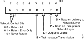
Use the Message Return bits to specify when a command sent to the system is returned to the host. When a message is returned, the network status byte indicates whether the command was processed successfully. Bit settings have the following effects:
Use the Test Message Transmission bit to verify that the system is receiving commands over the network. If you set this bit to 1, the system returns the command without processing it.
Use the Output to Logfile bit in conjunction with either the Trace on Pickup from Network Layer or Trace on Delivery to Network Layer bit. If you set both the Output to Logfile and one of the trace bits to 1, the entire message to/from the system is saved to the day's logfile on the system disk, and output to the system printer. This bit is useful for initial system debugging and diagnostic purposes only. For information on accessing and using the system logfile, refer to the Cisco VCO/4K System Administrator's Guide.
If you set the Trace on Pickup from Network Layer bit to 1, a message from the host to the system is output to the system printer when it is received by the system.
An additional trace facility allows tracing of all messages between the host and the system. Contact the Cisco Systems Customer Response Center for more information.
If you set the Trace on Delivery to Network Layer bit to 1, a message marked Return All (Message Return bits = 00) is output to the system printer when it is returned by the system. The message is also output to the system printer if it cannot be processed (Network Status byte not equal to $00) and the message is marked Return Error Only (Message Return bits = 01) or Return All (Message Return bits = 00).
The Network Status byte indicates the processing status of a message from the system. All event reports from the system (such as an Inpulse Rule Complete report) have a Network Status byte = $00. This value should also be used in any command sent by the host to the system.
Network Status bytes are the only way for the system to alert the host of a processing error for a specific command. All commands processed by the system set the Network Status byte. When the system returns a command to the host, the host interprets this byte to determine how a command was processed. To use this error indication effectively, commands from the host should have the Message Return bits set to Return All (00) or Return Error Only (01). Refer to "Network Status Byte Definitions," for a list of the network status byte values and a description of each.
![]()
![]()
![]()
![]()
![]()
![]()
![]()
![]()
Posted: Sat Sep 28 14:24:58 PDT 2002
All contents are Copyright © 1992--2002 Cisco Systems, Inc. All rights reserved.
Important Notices and Privacy Statement.