|
|

This chapter describes how to cable Ethernet communication links between a host computer and a VCO/4K system.
VCO/4K systems provide Ethernet socket connections to use as host links. You must provide cables, transceivers, and other link components to implement Ethernet links. The optional Ethernet Communications Package is available from Cisco Systems. The Cisco VCO/4K Ethernet Guide explains Ethernet implementation strategies.
The following general practices apply to host communication link cables:
Figure 4-1 shows two Storage/Control I/O Modules on the back of a redundant VCO/4K system. If your host requires an Ethernet communication link, connect it to the Ethernet port on the Storage/Control I/O Module.
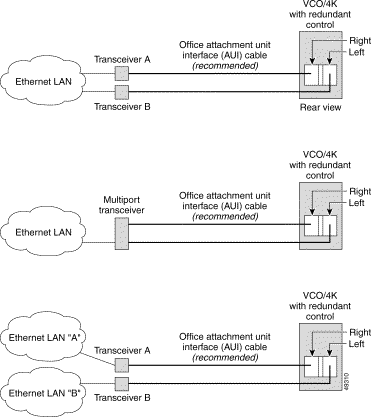
Figure 4-2 shows some possible Ethernet cabling configurations for communication links using the recommended cables and transceivers.

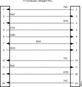
Table 4-1 shows the pinouts of each serial EIA/TIA-232 DB-25 connector on the Storage/Control I/O Module.
| Pin | Signal | Description |
|---|---|---|
2 | TxD | Transmit Data |
3 | RxD | Receive Data |
4 | RTS1 | Not used |
5 | CTS1 | Clear To Send |
6 | DSR1 | Data Set Ready |
7 | SGR | Signal Ground |
8 | DCD1 | Data Carrier Detect |
15 | TxC2 | Transmit Clock |
17 | RxC2 | Receive Clock |
20 | DTR1 | Data Terminal Ready |
24 | TxC2 | Transmit Clock |
| 1Modem support only. 2Supported on serial port 4 only. |
Jumpers on the Storage/Control I/O Module allow you to configure these ports as modem (DCE) terminations for connection to a terminal, or as DTE terminations for connection to a modem.
The factory settings for the Storage/Control I/O Module support the following configurations:
If other cable types or terminations are required, modify the jumper settings on the Storage/Control I/O Module. Refer to the Cisco VCO/4K Card Technical Descriptions for more information on jumper settings.
Figure 4-3 shows straight-through cables.

Figure 4-4 shows crossover (null modem) cables.

Table 4-2 shows the pinouts of the DB-15 Ethernet interface connector on the Storage/Control I/O Module.
| Pin | Signal | Description |
|---|---|---|
2 | C+ | Collision + (Input) |
3 | T+ | Transmit + (Output) |
5 | R+ | Receive + (Input) |
6 | GND | Ground |
9 | C- | Collision - (Input) |
10 | T- | Transmit - (Output) |
12 | R- | Receive - (Input) |
13 | +12VF | +12 VDC Power |
Cisco recommends that you use an office Attachment Unit Interface (AUI) cable between the Storage/Control I/O Module and a transceiver. You can order this cable from Cisco. The requirements of the physical Ethernet network determine the choice of transceiver type. For additional information on Ethernet networks, refer to the Cisco VCO/4K Ethernet Guide.
![]()
![]()
![]()
![]()
![]()
![]()
![]()
![]()
Posted: Sun Sep 29 07:24:24 PDT 2002
All contents are Copyright © 1992--2002 Cisco Systems, Inc. All rights reserved.
Important Notices and Privacy Statement.