|
|

The power subsystem in the VCO/4K Open Programmable Switch consists of the following main components:
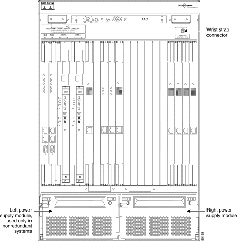
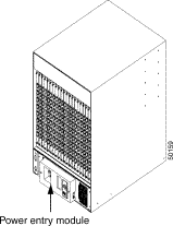
This subsystem is in the lower portion of the VCO/4K system. Figure 3-1 shows the front of a redundant system with the door removed and two power supply modules visible. Figure 3-2 shows the power entry module in the rear of the system. The power backplane is located internally, between the power supply modules and the power entry module.
The power subsystem powers the following:
The following specifications apply for the three power subsystem components, and the ring generator:
Operating Temperature | 10 to 40ºC (50 to 104ºF) |
Relative Humidity | 20 to 80% (noncondensing); temperature rise or fall should not exceed 10ºC (18ºF) per hour |
Part Number | DC: AC: Dual DC Kit: | Contact your Cisco Systems sales representative Contact your Cisco Systems sales representative Contact your Cisco Systems sales representative |
Physical Dimensions | Height: Width: Depth: | 5 in. (12.5 cm) 16 in. (40 cm) 3 in. (7.5 cm) |
Nominal Input Voltages | DC: AC: | -48 VDC 120 VAC or 240 VAC |
Part Number | AC DC | Contact your Cisco Systems sales representative Contact your Cisco Systems sales representative |
Physical Dimensions | Height: Width: Depth: | 5 in. (12.5 cm) 8 in. (20 cm) 7 in. (42.5 cm |
Output Voltages | All VDC: | +5, +15, -15, +12, +24, -48 |
Part Number | Contact your Cisco Systems sales representative | |
Physical Dimensions | Height: Width: Depth: | 4 in. (10 cm) 4 in. (10 cm) 1 in. (2.5 cm) |
Output Voltag: | 77 VAC |
|
The power entry module (PEM) serves as a mechanical connection point for site power. It includes the following (refer to Figure 3-4):
The PEM accepts AC or DC source voltages listed in Table 3-1.
 |
Note The power entry module accepts either a single-line AC feed, a dual-line DC feed, or a single-line DC feed. The factory-installed power supply modules are compatible with the power entry module configuration. The label on the power entry module will either specify your system's type of input power (see Figure 3-4) or list both possibilities (see Figure 3-5). Aways verify the input power type by looking at the front of each power supply module. Ensure that the power source is the correct current and voltage for your facility before cabling the power source. |
The line filter ensures that electromagnetic interference (EMI) neither enters nor exits the system.
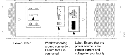
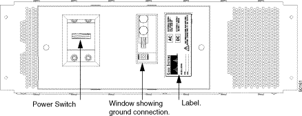
The VCO/4K can be purchased for AC or DC operation. Your system will come with either AC or DC power supplies, accordingly. Table 3-1 lists the power input ratings for AC or DC sources.
| Nominal | Range | Current | Frequency |
|---|---|---|---|
-48 VDC (per feed) | -40 to -60 VDC | 20 amps | DC |
120 VAC, single phase | 100 to 120 VAC | 10 amps | 50/60 Hz |
240 VAC, single phase | 208 to 240 VAC | 5 amps | 50/60 Hz |
Refer to the Cisco VCO/4K Hardware Installation Guide for information on proper wiring of input power. The VCO/4K system is shipped with a kit containing lugs for the input power cabling.
 |
Warning Do not open the power entry module (PEM) or you will void your Cisco Systems warranty. |
Table 3-2 indicates the required terminal (labeled TB1 through TB5) for each conductor, for the four possible input power sources. Refer to the Cisco VCO/4K Hardware Installation Guide for illustrations.
| Conductor | Terminal |
|---|---|
Single Feed -48 VDC (nominal) | |
Jumper 1 | TB1 to TB4 |
Jumper 2 | TB2 to TB5 |
Battery return (+) | TB4 |
Battery (-) | TB5 |
Ground | TB3 |
Dual Feed -48 VDC (nominal) | |
Battery Return A(+) | TB1 |
Battery A(-) | TB2 |
Battery Return B (+) | TB4 |
Battery B (-) | TB5 |
Ground | TB3 |
Single Feed 120 VAC (nominal) | |
Neutral | TB5 |
Line | TB2 |
Ground | TB3 |
Single Feed 240 VAC (nominal) | |
Line 1 | TB2 |
Line 2 | TB5 |
Ground | TB3 |
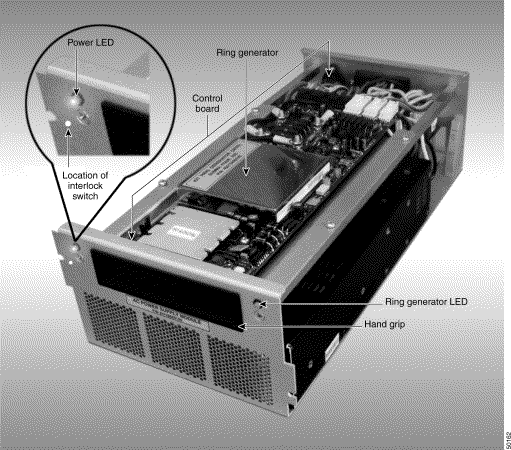
There are two LEDs on the front of the power supply module: the power LED on the left side, and the Ring Generator LED on the right side. See Figure 3-5.
The power LED is on the upper left side of the power supply module. When illuminated, it is either green or red.
The Ring Generator LED is on the upper right side of the power supply module. When illuminated, it is either green or red.
The interlock switch is under the power LED. Use this switch to remove and replace power supply modules while the system is running. To safely remove the power supply module, turn off the output power (switch in the open position). Remove the upper left screw to open the interlock switch. Refer to Figure 3-5. Refer to the "Removal and Replacement Procedures" section for instructions on removing a redundant power supply module.
When you close the interlock switch, the output power is turned on, and the power supply module is operational.
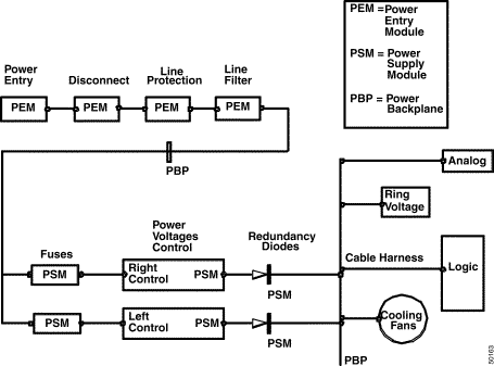
Input power from the power entry module travels through the power backplane to the power supply module where it is converted to usable voltages. The power supply module distributes the voltages to the power backplane, which distributes it to the rest of the system.
The power backplane contains:
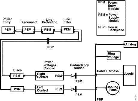
Figure 3-6 is a system-level functional diagram of the power subsystem for single-feed AC/DC operation. Figure 3-7 is the diagram for dual-feed DC operation.
 |
Note If you want single DC input power, you must install two external jumpers: a/rtn to b/rtn and a/bat to b/bat. This way, both power supply modules are powered from a common feed. |
The main power supply module is on the left of all VCO/4K systems. In nonredundant systems, ensure that the power supply module is on the left.
The following describes the power supply load-sharing and redundancy in VCO/4K systems:
The power supply module provides six regulated DC voltages for system operation, as shown in Table 3-3.
.
| Voltage | Tolerance | Current |
|---|---|---|
+5 VDC | ±0.25V | 84 amps |
+15 VDC | ±0.5V | 4 amps |
-15 VDC | ±0.5V | 4 amps |
+12 VDC | +3V, -0V | 1 amp |
+24 VDC | ±1.0V | 1 amp |
-48 VDC | ±4.0V | 3 amps |
The ring generator is active only when it is installed in the left power supply module. Ring generators can be installed in both power supply modules in a redundant system. However, the ring generator in the right power supply module is not connected to the system and is considered a spare. Power loss to the left power supply module results in loss of the ring generator (if installed).
The two circuit configuration jumpers, JP6 and JP7, on the power supply module, are configured as shown in Table 3-4 when the VCO is shipped with a ring generator installed. This configuration is required for proper operation of the ring generator alarm and its LED. Refer to the "Indicator LEDs" section for information about the LED.
If your system has a ring generator, you must install JP7, in the left module only.
| Configuration | JP6 | JP7 |
|---|---|---|
Right Power Supply Module | Install when ring generator is present | Remove |
Left Power Supply Module | Remove | Remove |
Left Power Supply Module | Install | Install |
 |
Note If you install a ring generator, configure the JP6 and JP7 jumpers. The ring generator kit includes installation instructions. |
Follow ESD rules when removing or replacing a system component. Use a wrist strap connected to the system for grounding. See Figure 3-1.
 |
Warning Voltages present on the power backplane and at other test points produce severe, perhaps fatal electrical shock. Observe all precautions normally associated with the testing of electrical equipment. Turn off power at the source before performing any serv-ice. |
 |
Caution Follow ESD rules when removing a system component. Use a wrist strap for grounding. |
To remove a nonredundant power supply module:
Step 1 Turn the switch off on the power entry module if the system does not contain redundant power supply modules, or if both power supply modules are to be removed simultaneously. The power disconnect switch is located in the rear of the system on the power entry module (see Figure 3-4).
Step 2 Remove the front door of the VCO/4K system to access the power supply module.
Step 3 Connect your wrist strap to the system (upper right corner). See Figure 3-1.
Step 4 Remove the two mounting screws on the front panel of the power supply module.
When the upper left screw is removed, the power is cut off from the module (the power LED is off).
 |
Note If the LED is faintly illuminated red, and the interlock switch screw is removed, it is safe to remove the power module. |
Step 5 Grasp the black hand grip on the front of the module with one hand and pull the module out. Use your other hand to provide support underneath the module as you remove it from the system.
To remove a redundant power supply module:
Step 1 Remove the front door of the VCO/4K system to access the power supply module.
Step 2 Connect your wrist strap to the system (upper right corner). See Figure 3-1.
Step 3 Remove the two mounting screws on the front panel of the power supply module.
When the upper left screw is removed, the power is cut off from the module (the power LED is off).
 |
Note If the LED is faintly illuminated red, and the interlock switch screw is removed, it is safe to remove the power module. |
Step 4 Grasp the black hand grip on the front of the module with one hand and pull the module out. Use your other hand to provide support underneath the module as you remove it from the system.
 |
Caution Follow ESD rules when removing a system component. Use a wrist strap for grounding. |
To replace a power supply module:
Step 1 If the power supply module is nonredundant, ensure that the power is off.
Step 2 Remove the front door of the VCO/4K system to access the power supply module.
Step 3 Connect your wrist strap to the system (upper right corner). See Figure 3-1.
Step 4 Grasp the black hand grip on the front of the module with one hand and use your other hand to provide support underneath the module as you push it into its compartment.
Step 5 Fasten the two mounting screws on the front panel of the power supply module.
 |
Note Ensure that you rotate the plate into position to align the left mounting screw before fastening the screw into place. |
Step 6 If necessary, turn the VCO/4K system on.
Step 7 Remove your wrist strap.
Step 8 Check the power LED and ensure that the power supply module is operating. Refer to the "Indicator LEDs" section for information on the LED.
Step 9 Replace the front door.
 |
Caution The front door must remain on during system operation for EMI compliance. |
 |
Note More extensive troubleshooting information is contained in the Cisco VCO/4K Troubleshooting Guide. |
The following two events occur simultaneously when voltage monitoring on the control board of the power supply module detects either an over- or undervoltage condition:
When these two events occur, you must replace the power supply module. Refer to the "Removal and Replacement Procedures" section.
One spare fuse kit containing two 25-amp fuses comes with the VCO/4K. A fuse is on the back of each power supply module.
![]()
![]()
![]()
![]()
![]()
![]()
![]()
![]()
Posted: Sat Sep 28 09:53:58 PDT 2002
All contents are Copyright © 1992--2002 Cisco Systems, Inc. All rights reserved.
Important Notices and Privacy Statement.