|
|

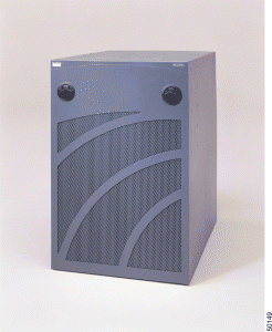
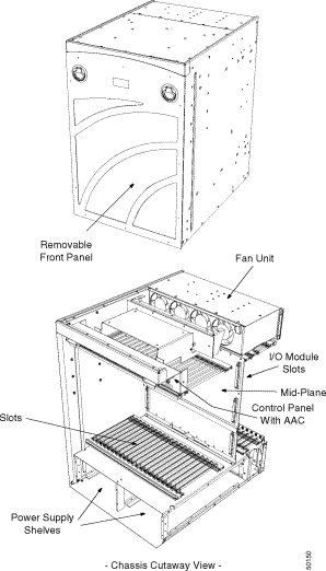
The VCO/4K system enclosure is a metal-based cabinet that houses all the VCO/4K critical system components including: the fan cooling unit; the alarm arbiter and interface cards; and high-density system hardware cards. It also accommodates the power subsystem, either single or dual for system redundancy. Figure 1-1 shows the front of a VCO/4K system. Figure 1-2 shows a cutaway view of the chassis underneath the enclosure.
The system enclosure meets or exceeds the following enclosure requirements:
Part Number | Contact your Cisco Systems sales representative |
Front Door | Removable front door with locking feature |
Enclosure Dimensions | Height: 26.13 inch (67.73 cm) |
| Width: 17.5 inch (45.33 cm) |
| Depth: 22.5 inch (58.57 cm) |
Footprint | 22.50 in. by 17.5 in. (57.15 cm by 45.33 cm) |
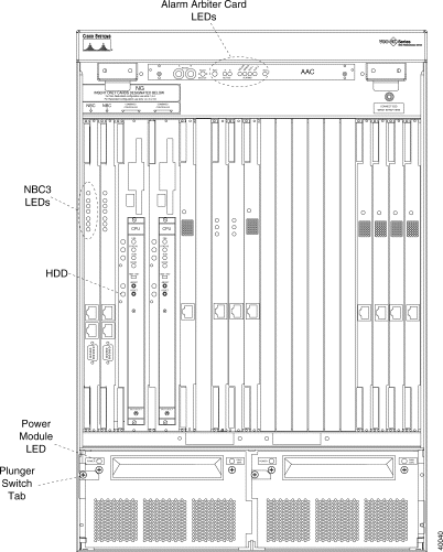
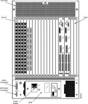
The VCO/4K system enclosure is designed for environments that require UL 1950 enclosures. Venting holes on the front door provide air flow to cool system components when the system fan units are operational. A removable air filter is held in place by a cross-member and two screws on the inside of the front door. Four screw-in rubber foot pads for bench use are provided as an option. All cable access is through the back of the system enclosure. Figure 1-3 shows the front of a VCO/4K with the door off. Figure 1-4 shows the back of the system enclosure.
The VCO/4K front door has a lock for security purposes. Two door frame latches at the top and two studs at the bottom hold the door in place.
 |
Caution The front door must remain on during system operation for NEBS EMI compliance. |
The inside of the door contains an air filter made of UL 94 HF-1 foam. The removable air filter should be regularly vacuumed to remove any accumulated dust.
To remove the front door:
Step 1 If necessary, unlock the front door. The lock is located at the center of the door between the door latches.
Step 2 Flip up the two door latches located to the right and left of the lock. Hold the latches and pull the door approximately three inches away from the system enclosure. Grasp the sides of the door and lift it up and away to clear the studs located at the base of the enclosure.
Step 3 Carefully remove the door and place it in an area where it will not become damaged.
To install the front door:
Step 1 Grasp the sides of the door and position it so that the bottom is aligned with the studs located at the base of the enclosure.
Step 2 Flip up the two door latches located to the right and left of the lock. Hold the latches in the open position and push the door toward the system enclosure until it snaps closed. Press the door latches in.
Step 3 Lock the door.
 |
Caution To ensure security, always lock the front door of the enclosure after you have performed service procedures. |
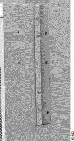
The VCO/4K may be installed in an EIA standard cabinet that is 19 inches wide. If the VCO/4K will be installed in a cabinet or rack, a mounting shelf must be secured to the cabinet/rack and a mounting brace must be secured to the VCO/4K before it is lifted and placed in the cabinet or rack. Figure 1-5 shows the mounting brace (one on each side) for the VCO/4K.
Refer to the Cisco VCO/4K Site Preparation Guide for specifications on the mounting brace and shelf. Refer to the Cisco VCO/4K Hardware Installation Guide for information on attaching the mounting brace and shelf.
Two rear support holes are located at the base of the each side panel. You have the option of fabricating and attaching brackets for additional support when mounting the VCO/4K in a cabinet or rack.
If the VCO/4K is mounted in a cabinet or rack, you must remove it from the cabinet or rack before moving it to another location.
 |
Caution Follow ESD rules when removing system components. Be sure to use a wrist strap for grounding. At least two people are required to move the system enclosure. |
To move the system enclosure:
Step 1 Power down the system by turning off the power switch at the rear of the enclosure.
Step 2 Disconnect the power connector from the power entry module.
Step 3 Remove the EIA/TIA-232 serial cables, parallel printer cables, and optional Ethernet transceiver cables connected to the rack. Be sure that all EIA/TIA-232 cables are properly labeled so that they can be rerouted and reinstalled, as necessary.
Step 4 Remove the network cables from the I/O modules. Be sure that all cables are properly labeled so that they can be rerouted and reinstalled, as necessary.
Step 5 Disconnect earth ground to the system at the ground point within the enclosure.
Step 6 Remove the power supply module(s) to decrease the weight of the system. For more information, refer to "VCO/4K Power Subsystem."
Step 7 If the VCO/4K is installed in a cabinet or rack, remove the VCO/4K from the cabinet or rack.
Step 8 Move the system as follows:
a. To move the system to another location in the same room, lift it into position.
b. To move the system to another location outside the room, repack the system enclosure, including the power supply modules, in the original shipping container.
The VCO/4K system enclosure must be installed to meet the clearance, environmental, and power criteria specified in the Cisco VCO/4K Site Preparation Guide. To reinstall the system enclosure, follow the procedures in the Cisco VCO/4K Hardware Installation Guide.
The system enclosure provides passive mechanical and electrical connections to the card rack and power subsystem. It is highly unlikely that the system enclosure will cause a system failure in the course of normal operation. The most likely cause of damage to a system enclosure is mechanical damage resulting in a misalignment of racks or an electrical short circuit within the rack cabling. More specific causes of damage include:
To minimize any chance of mechanical or electrical damage to the enclosure, follow the recommended system clearances and central office practices for handling the MDF/digital cross-connectors and power connections. If mechanical or electrical damage does occur, refer to the troubleshooting information in the appropriate Cisco Systems technical description for the damaged component.
![]()
![]()
![]()
![]()
![]()
![]()
![]()
![]()
Posted: Sat Sep 28 09:54:01 PDT 2002
All contents are Copyright © 1992--2002 Cisco Systems, Inc. All rights reserved.
Important Notices and Privacy Statement.